WEIHONG NK105 User manual

上海维宏电子科技股份有限公司
SHANGHAI WEIHONG ELECTRONIC TECHNOLOGY CO., LTD.
Manufacturer Manual of NK105 Integrated CNC System
(Applicable to NK105G3 Handheld Box)
Version: 2020.5 1st Version
Author: Product Supporting Department
Weihong Corporation, All Rights Reserved
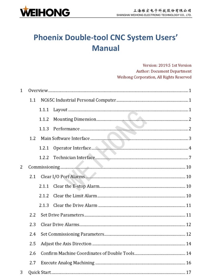
1 System overview................................................................................................................................................. 1
1.1 NK105 (E) Control Box with Four Axes................................................................................. 1
1.1.1 Schematic Diagram.............................................................................................................. 2
1.1.2 Dimension Drawing (Unit: mm) .................................................................................. 3
1.2 NK105G3 Handheld Box.................................................................................................................. 3
1.2.1 Button Definition................................................................................................................... 4
1.2.2 Dimension Drawing (Unit: mm) ............................................................................... 10
1.3 Main Software Interface............................................................................................................... 10
1.3.1 General NK105 with Four Axes................................................................................. 11
1.3.2 General NK105 with Double Z Axes ....................................................................... 12
2 Wiring..................................................................................................................................................................... 13
2.1 Signal Type ........................................................................................................................................... 13
2.1.1 Binary Input Signal........................................................................................................... 13
2.1.2 Open Collector Output Signal ..................................................................................... 14
2.1.3 Analog Output Signal....................................................................................................... 14
2.1.4 Differential Output Signal............................................................................................. 15
2.2 Terminal Definition......................................................................................................................... 15
3 Basic Commissioning .................................................................................................................................... 16
3.1 Start the System................................................................................................................................. 16
3.2 Select the Axis Mode....................................................................................................................... 17

上海维宏电子科技股份有限公司
SHANGHAI WEIHONG ELECTRONIC TECHNOLOGY CO., LTD.
3.3 Activate the Axis................................................................................................................................ 17
3.4 Adjust the Port Polarity ................................................................................................................ 18
3.5 Set Pulse Equivalent........................................................................................................................ 19
3.6 Adjust the Axis Direction............................................................................................................. 20
3.7 Set the Workbench Travel........................................................................................................... 21
3.8 Set the Machine Origin .................................................................................................................. 22
3.9 Set the Spindle.................................................................................................................................... 23
4 Quick Start ........................................................................................................................................................... 24
4.1 Execute Returning to the Machine Origin ......................................................................... 24
4.2 Load a Program File ........................................................................................................................ 25
4.3 Select a WCS......................................................................................................................................... 27
4.4 Define the Workpiece Origin ..................................................................................................... 28
4.4.1 General NK105 with Four Axes................................................................................. 28
4.4.2 General NK105 with Double Z Axes ....................................................................... 29
4.5 Set the Tool Number....................................................................................................................... 30
4.6 Execute Fixed Calibration............................................................................................................ 31
4.7 Start Machining.................................................................................................................................. 32
4.8 Adjust Machining.............................................................................................................................. 32
4.8.1 Adjust the Feedrate Override..................................................................................... 32
4.8.2 Adjust the Spindle Speed............................................................................................... 33
4.8.3 Execute the Fine Adjustment...................................................................................... 33
4.8.4 Handle the Soft Limit....................................................................................................... 34
4.8.5 Handle the Hard Limit .................................................................................................... 35
5 Common Operations...................................................................................................................................... 35
5.1 Set the Machining Wizard........................................................................................................... 35
5.2 Execute Selective Machining ..................................................................................................... 37
5.3 Parse the Simulation Range ....................................................................................................... 38

上海维宏电子科技股份有限公司
SHANGHAI WEIHONG ELECTRONIC TECHNOLOGY CO., LTD.
5.4 Set the Stop Position....................................................................................................................... 39
5.5 Use Array Machining...................................................................................................................... 40
5.6 Save the Workpiece Origin ......................................................................................................... 41
5.7 Select an Adjacent Point for Machining .............................................................................. 42
6 Parameter Maintenance.............................................................................................................................. 43
6.1 Back up Parameters........................................................................................................................ 43
6.2 Restore Back-up Parameters..................................................................................................... 44
6.3 Restore Parameters to Factory Settings............................................................................. 44
6.4 Export Parameters........................................................................................................................... 45
6.5 Import Parameters .......................................................................................................................... 46
6.6 Import the Compensation File.................................................................................................. 46
7 System Maintenance...................................................................................................................................... 47
7.1 Switch the Language....................................................................................................................... 47
7.2 Export Logs........................................................................................................................................... 47
7.3 Update the System........................................................................................................................... 48
7.4 Update the System Application................................................................................................ 49
7.5 Update the System Image............................................................................................................ 50
7.6 Use Registration................................................................................................................................ 51
7.7 Use Writing Numbers..................................................................................................................... 52
7.8 Set Help Interface............................................................................................................................. 53
7.9 Restart the System........................................................................................................................... 54
7.10 Exit the System................................................................................................................................ 54
7.11 Delete Logs........................................................................................................................................ 55
7.12 Check Disk Space............................................................................................................................ 55
7.13 Modify the Manufacturer Password .................................................................................. 56
8 System Diagnosis............................................................................................................................................. 57
8.1 Check System Information.......................................................................................................... 57

上海维宏电子科技股份有限公司
SHANGHAI WEIHONG ELECTRONIC TECHNOLOGY CO., LTD.
8.2 Check Buttons..................................................................................................................................... 57
8.3 Check Input Ports............................................................................................................................. 58
8.4 Check Output Ports.......................................................................................................................... 59
8.5 Check LED Lights.............................................................................................................................. 60
9 System Parameters........................................................................................................................................ 61
9.1 Operator Parameters...................................................................................................................... 61
9.1.1 Machining Wizard.............................................................................................................. 61
9.1.2 Velocity..................................................................................................................................... 62
9.1.3 Returning to the Machine Origin before Machining..................................... 62
9.1.4 Z Position at Pause............................................................................................................ 63
9.1.5 Offset.......................................................................................................................................... 64
9.1.6 Cycle Machining.................................................................................................................. 64
9.1.7 Command................................................................................................................................ 65
9.1.8 Stopping the Spindle........................................................................................................ 66
9.1.9 Override................................................................................................................................... 66
9.1.10 File............................................................................................................................................ 67
9.1.11 Tool Change........................................................................................................................ 70
9.1.12 Red Light .............................................................................................................................. 71
9.1.13 Calibration Height .......................................................................................................... 71
9.1.14 Tool Compensation........................................................................................................ 71
9.2 Manufacturer Parameters........................................................................................................... 72
9.2.1 Velocity..................................................................................................................................... 72
9.2.2 Axis Output Direction...................................................................................................... 77
9.2.3 Pulse Equivalence.............................................................................................................. 77
9.2.4 Workbench Travel............................................................................................................. 77
9.2.5 Tool Change Travel........................................................................................................... 78
9.2.6 Travel Limit ........................................................................................................................... 78

上海维宏电子科技股份有限公司
SHANGHAI WEIHONG ELECTRONIC TECHNOLOGY CO., LTD.
9.2.7 Machine Origin .................................................................................................................... 78
9.2.8 Spindle...................................................................................................................................... 79
9.2.9 Rotary Axis............................................................................................................................. 80
9.2.10 A-axis...................................................................................................................................... 81
9.2.11 Compensation................................................................................................................... 82
9.2.12 Presetter Thickness....................................................................................................... 83
9.2.13 Interpolation Algorithm.............................................................................................. 83
9.2.14 Arc Increment ................................................................................................................... 83
9.2.15 Arc Radius Tolerance.................................................................................................... 84
9.2.16 Look-ahead Segment .................................................................................................... 84
9.2.17 Origin Sign........................................................................................................................... 84
9.2.18 Safety Height...................................................................................................................... 85
9.2.19 Lubrication.......................................................................................................................... 85
9.2.20 G00 Feed 100 Percent.................................................................................................. 86
9.2.21 Smoothing Time............................................................................................................... 86
9.2.22 Corner Option.................................................................................................................... 86
9.2.23 Corner Tolerance ............................................................................................................ 87
9.2.24 Spindle Space..................................................................................................................... 87
9.2.25 Decreasing Time to Soft Limit................................................................................. 87
9.2.26 Smoothing Time for Override ................................................................................. 87
9.2.27 Override Acceleration .................................................................................................. 88
9.2.28 Deceleration Time at Pause...................................................................................... 88
10 Drive Parameters and Wiring Diagrams........................................................................................ 89
10.1 Drive Parameters........................................................................................................................... 89
10.2 Wiring Diagrams between NK105(E) Control Box and Different Drives.... 90
10.2.1 Stepping Drive with Differential Input.............................................................. 90
10.2.2 WISE Servo Drive............................................................................................................ 91

上海维宏电子科技股份有限公司
SHANGHAI WEIHONG ELECTRONIC TECHNOLOGY CO., LTD.
10.2.3 YASKAWA Σ–ⅡServo Drive.................................................................................... 91
10.2.4 DELTA ASDA Servo Drive .......................................................................................... 92
10.2.5 PANASONIC MINAS_A4 Servo Drive ................................................................... 93
10.2.6 MITSUBISHI MR-E Servo Drive.............................................................................. 93
10.2.7 FUJI FALDIC-β Servo Drive ....................................................................................... 94
10.2.8 STONE GS Servo Drive.................................................................................................94
11 Legal Notices................................................................................................................................................... 95
11.1 Description of Further Rights and Restrictions:......................................................... 95
11.2 Intellectual Property Rights Notice:................................................................................... 96
11.3 After-sales Guarantee:................................................................................................................ 96
11.4 Limitation of Liability: ................................................................................................................ 96
11.5 Termination:..................................................................................................................................... 96
11.6 Applicable Law:............................................................................................................................... 97

上海维宏电子科技股份有限公司
SHANGHAI WEIHONG ELECTRONIC TECHNOLOGY CO., LTD.
1/ 97
1System overview
NK105 Integrated CNC System (Hereinafter referred to as NK105) is an integrated
CNC system with three or four axes, based on embedded industrial control platform
and independently developed by Weihong Company.
According to axes, NK105 has the following types:
•General NK105 with three axes: Including X-axis, Y-axis and Z-axis.
•General NK105 with four axes: Including X-axis, Y-axis, Z-axis and A-axis.
•General NK105 with double Z axes: Including X-axis, Y-axis, Z1-axis and Z2-axis.
Hardware
•NK105(E) control box with four axes / NK105 control box with three axes
The two control boxes are almost the same, except the former supports A-axis
or Z2-axis.
This manual takes NK105(E) control box with four axes as an example.
•NK105G3 handheld box.
Software
About the main interface of NK105, see Main Software Interface.
1.1 NK105 (E) Control Box with Four Axes
This section introduces the schematic diagram and dimension drawing o f NK105 (E)
control box with four axes.
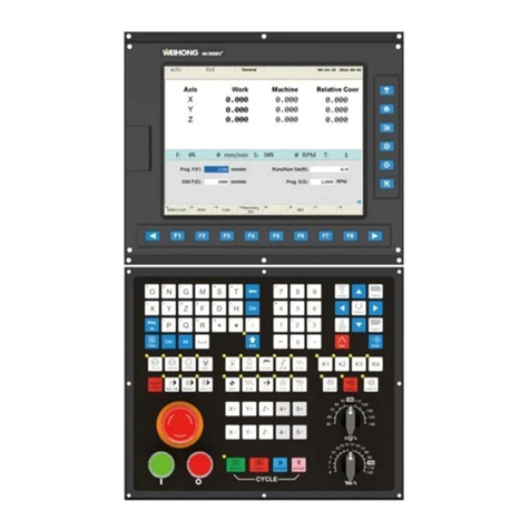
This control box, an integration of the system control card, terminal board and other
parts, connects to the handheld box with 15-core connecting cable. And the up and
down ends at its back are for terminals and the left side is for the USB interface and
DB15 interface.

上海维宏电子科技股份有限公司
SHANGHAI WEIHONG ELECTRONIC TECHNOLOGY CO., LTD.
2/ 97
1.1.1 Schematic Diagram
This schematic diagram of NK105 (E) control box with four axes is as follows:
1. USB interface
It allows NK105 to communicate with other devices.
2. DB15 interface
It is used to connect to a handheld box.
3. +24V IN input interface
It is used to connect to a 24V DC power supply.
4. GND
It is used to connect to the port GND or COM of a DC power supply.

上海维宏电子科技股份有限公司
SHANGHAI WEIHONG ELECTRONIC TECHNOLOGY CO., LTD.
3/ 97
5. A-axis differential signals
About terminal definition of the control box, see Terminal Definition.
Note: It is only applicable to NK105 (E) control box with four axes.
1.1.2 Dimension Drawing (Unit: mm)
The thickness of NK105 (E) control box with four axes is 218.3mm.
The dimension drawing is as follows:
1.2 NK105G3 Handheld Box
This section introduces the button definitions on NK105G3 handheld box and
dimension drawing of the handheld box.
The handheld box is connected to the control box with a connecting cable, jointly
controlling a machine tool. So the moving distance of the handheld box and control
box is limited by the connecting cable.
Note: This handheld box is updating. And you can check the newest usage of a single button and button
combinations in Help Information interface by pressing + .

上海维宏电子科技股份有限公司
SHANGHAI WEIHONG ELECTRONIC TECHNOLOGY CO., LTD.
4/ 97
1.2.1 Button Definition
The definitions of buttons on NK105G3 handheld box are as follows:
•A single button
–: It is used to start machining.
–: It is used to pause machining.
–: It is used to stop machining.
–: Arrow button (up).
–: Arrow button (down).
–: Arrow button (left).
–: Arrow button (right).
–: It is used to enable / disable the spindle.
–: It is used to enter the menu interface, or enter the interface for
updating the system image at the time of starting NK105.

上海维宏电子科技股份有限公司
SHANGHAI WEIHONG ELECTRONIC TECHNOLOGY CO., LTD.
5/ 97
–: It is used to exit the current interface or dialog box, or return
to the previous interface.
–: It is used to clear the workpiece coordinates of X-axis and Y-
axis at the same time.
–:
•General NK105 with four axes: It is used to clear the workpiece
coordinate of Z-axis or A-axis.
•General NK105 with double Z axes: It is used to clear the
workpiece coordinate of Z1-axis.
–: It is an auxiliary key or used to switch between Jog and Step
mode in the main interface.
–: It is used to increase the feedrate override.
–: It is used to decrease the feedrate override.
–: It is used to move X-axis / Y-axis to the workpiece origin or
input the figure 0.
–: It is used to move X-axis in the negative direction or input the
figure 4.

上海维宏电子科技股份有限公司
SHANGHAI WEIHONG ELECTRONIC TECHNOLOGY CO., LTD.
6/ 97
–: It is used to move X-axis in the positive direction or input the
figure 6.
–: It is used to move Y-axis in the positive direction or input the
figure 8.
–: It is used to move Y-axis in the negative direction or input the
figure 2.
–:
•General NK105 with four axes: It is used to move Z-axis in the
positive direction or input the figure 9.
•General NK105 with double Z axes: It is used to move Z1-axis in
the positive direction or input the figure 9.
–:
•General NK105 with four axes: It is used to move Z-axis in the
negative direction or input the figure 3.
•General NK105 with double Z axes: It is used to move Z1-axis in
the negative direction or input the figure 3.
–: It is used to switch between high-speed jog mode and slow jog
mode or input the figure 5.

上海维宏电子科技股份有限公司
SHANGHAI WEIHONG ELECTRONIC TECHNOLOGY CO., LTD.
7/ 97
–:
•General NK105 with four axes: It is used to move A-axis in the
positive direction or input the figure 7.
•General NK105 with double Z axes: It is used to move Z2-axis in
the positive direction or input the figure 7.
–:
•General NK105 with four axes: It is used to move A-axis in the
negative direction or input the figure 1.
•General NK105 with double Z axes: It is used to move Z2-axis in
the negative direction or input the figure 1.
•Button combination
–+ : Breakpoint resume.
–+ : It is used to show help information.
–+ : It is used to clear the workpiece coordinate of X-
axis.
–+ :
•General NK105 with four axes: It is used to clear the workpiece
coordinate of Y-axis.
•General NK105 with double Z axes: It is used to clear the
workpiece coordinate of Z2-axis.

上海维宏电子科技股份有限公司
SHANGHAI WEIHONG ELECTRONIC TECHNOLOGY CO., LTD.
8/ 97
–+ : It is used to increase the spindle override.
–+ : It is used to decrease the spindle override.
–+ : It is used to move X-axis or Y-axis to the fixed point.
–+ : It is used to select the workpiece coordinate system
(WCS) from G59 to G54.
–+ : It is used to select the WCS from G54 to G59.
–+ : It is used to do centering for X-axis.
–+ : It is used to do centering for Y-axis.
–+ : It is used to return to the machine origin (ie. the
origin of the machine coordinate system (MCS)).
–+ : It is used to switch between workpiece coordinates
and machine coordinates .
–+ : It is used to calibrate tool.

上海维宏电子科技股份有限公司
SHANGHAI WEIHONG ELECTRONIC TECHNOLOGY CO., LTD.
9/ 97
–+ : It is used to make the fine adjustment.
•Button combination (Exclusive to General NK105 with double Z axes)
–+ : It is used to clear the workpiece coordinate of Y-
axis.
–+ : It is used to activate axes.
–+ : It is used to switch between Alternative and
Linkage mode. See Select the Aixs Mode for details.
–+ : It is used to set the tool length of Z1-axis.
–+ : It is used to set the tool length of Z2-axis.

上海维宏电子科技股份有限公司
SHANGHAI WEIHONG ELECTRONIC TECHNOLOGY CO., LTD.
10 / 97
1.2.2 Dimension Drawing (Unit: mm)
The dimension drawing of NK105G3 handheld box is as follows:
1.3 Main Software Interface
The main software interface differs in axes. General NK105 with four axes and that
with three axes are the same, except the axis number, so their main interfaces are
similar. Therefore, this manual does not introduce the main interface of general
NK105 with three axes.

上海维宏电子科技股份有限公司
SHANGHAI WEIHONG ELECTRONIC TECHNOLOGY CO., LTD.
11 / 97
1.3.1 General NK105 with Four Axes
When general NK105 with four axes starts, the system automatically enters the
machining interface in the manual mode (ie. Jog or Step mode).
The main interface is as follows:
1. Activated axes
The figures refer to the selected WCS. Specifically, 1/ 2/ 3/ 4/ 5/ 6
respectively refers to G54/ G55/ G56/ G57/ G58/ G59.
2. Coordinates
3. Operation status
–Idle: Default status.
–Running
–Pause
–Stop
–Locked: NK105 is locked when the soft limit is triggered.
4. Spindle status
–Enabled
–Disabled
5. Speed mode
–High-speed jog
–Slow jog mode
6. Motion mode
–Jog: Finely adjust the machine coordinate.
–Step: Coarsely adjust the machine coordinate.

上海维宏电子科技股份有限公司
SHANGHAI WEIHONG ELECTRONIC TECHNOLOGY CO., LTD.
12 / 97
1.3.2 General NK105 with Double Z Axes
The main interface is as follows:
1. Activated axes
2. Coordinates
3. Operation status
–Idle: Default status.
–Running
–Pause
–Stop
–Locked: NK105 is locked when the soft limit is triggered.
4. Spindle status and coordinate system
–Spindle status
•Enabled
•Disabled
–Coordinate system
When the coordinate system turns to show the MCS, this area shows G53;
when it turns to the WCS, this area shows G54 (default one) / G55 / G56
/ G57 / G58 / G59.
5. Speed mode
–High-speed jog
–Slow jog mode
6. Motion mode
–Jog: Finely adjust the machine coordinate.
–Step: Coarsely adjust the machine coordinate.

上海维宏电子科技股份有限公司
SHANGHAI WEIHONG ELECTRONIC TECHNOLOGY CO., LTD.
13 / 97
2Wiring
Through this section, you can quick know the supported signal types and terminal
definition of NK105 (E) control box with four axes, which can help you finish
wiring.
2.1 Signal Type
The signal types include the following:
•Binary input signal
•Open collector output signal
•Analog output signal
•Differential output signal
2.1.1 Binary Input Signal
The wiring diagram of the binary input terminal connected to the following switches
is as follows:
•Mechanical switch
•Photoelectric switch or proximity switch

上海维宏电子科技股份有限公司
SHANGHAI WEIHONG ELECTRONIC TECHNOLOGY CO., LTD.
14 / 97
When the binary input terminal is connected to 24V, the input signal is active low:
•For a normal open switch, conducting to GND means the input signal can be
received .
•For a normal close switch, disconnecting with GND means the input signal can
be received.
2.1.2 Open Collector Output Signal
The output port of NK105 (E) control box with four axes belongs to open
controller output, with the maximum output current 50mA.
The wiring diagram of the output port connected to a solid-state relay is as follows:
2.1.3 Analog Output Signal
SAV, an output port for 0V ~ 10V controllable voltage, is connected to the input port
for analog voltage frequency of the inverter. Therefore, you can control the inverter
frequency by changing the controllable voltage, so as to control the spindle speed.
The schematic diagram is as follows:
This manual suits for next models
2
Table of contents
Other WEIHONG Control System manuals

WEIHONG
WEIHONG NC65C User manual

WEIHONG
WEIHONG NK280B User manual

WEIHONG
WEIHONG Ncstudio V15 User manual

WEIHONG
WEIHONG NK300CX User manual

WEIHONG
WEIHONG NCStudio V12 User manual

WEIHONG
WEIHONG NcEditor V12 User manual

WEIHONG
WEIHONG NcEditor V12 User manual

WEIHONG
WEIHONG LS1500 User manual

WEIHONG
WEIHONG 200 Series User manual

WEIHONG
WEIHONG NK105 G2F User manual