Force America SSC3100 Use and care manual

SSC3100 Operation
and
Calibration Manual


SSC3100 Operation & Calibration Manual
Welcome and Table of Contents
i
Welcome
Congratulations on your purchase of a FORCE America®, Inc. SSC3100 Spreader Control. This
manual will guide you through the process of using your new spreader control.
Table of Contents
Welcome ...........................................................................................................i
Table of Contents.............................................................................................i
Hardware..........................................................................................................1
Powering up the SSC3100..............................................................................2
Normal Operation Mode..................................................................................3
Applying Material.................................................................................................................. 4
Blast ....................................................................................................................................... 6
Unload..............................................................................................................7
Calibration........................................................................................................9
Description of Calibration Values................................................................10
Spreader Min Duty Cycle.................................................................................................... 10
Spreader Max Duty Cycle................................................................................................... 10
Spinner Min Duty Cycle...................................................................................................... 11
Spinner Max Duty Cycle..................................................................................................... 11
Liquid Min Duty Cycle ........................................................................................................ 11
Liquid Max Duty Cycle........................................................................................................ 12
Blast Time............................................................................................................................ 12
Speedometer Configuration .............................................................................................. 13
Liquid Mode......................................................................................................................... 13
Restore Defaults ................................................................................................................. 14
Firmware Version................................................................................................................ 14
Troubleshooting and Error Conditions .......................................................15
FORCE America Contact Information..........................................................18


SSC3100 Operation & Calibration Manual
Hardware
1
Hardware
The SSC3100 is a self-contained spreader system. It has three rotary adjustment knobs with
pushbuttons.
Figure 1: The SSC3100

SSC3100 Operation & Calibration Manual
Power Up the SSC3100
2
Powering up the SSC3100
Upon applying 12V DC dashkey power to the SSC3100, the system will perform a panel test by
illuminating the LEDs around the dials as well as the ACTIVE and BLAST LEDs. During this test
the outputs will remain inactive. The system will also perform a test on the various system inputs.
If the system detects any errors on startup the ACTIVE LED and BLAST LED will alternately flash
RED to indicate that an error was detected. The error code will be displayed using the Spreader
and Spinner dial indicators. If no errors are detected on startup the system will enter normal
operation mode in standby.

SSC3100 Operation & Calibration Manual
Normal Operation
3
Normal Operation Mode
When the spreader control is in normal operation mode the output set rates are indicated by the
illuminated number next to the corresponding dial from zero to the active rate. The output rates
represent the percentage of output between the min and max calibration settings.
The numbers around the liquid dial will be illuminated when the liquid system is active. When the
liquid system is turned off all the numbers around the dial will be off. Pressing the liquid knob will
turn on and off the liquid application, if it is enabled. The liquid output operation will also follow
the standby state of the spreader control, if enabled.

SSC3100 Operation & Calibration Manual
Applying Material
4
Applying Material
When your SSC3100 system starts up, it will always be in standby with all outputs inactive. You
will need to remove your system from standby before it will apply material.
The spreader can apply granular material only (Dry Granular Application), apply a prewet liquid to
the granular material while spreading (Prewetted Granular Application) or apply liquid only (Direct
Liquid Application).
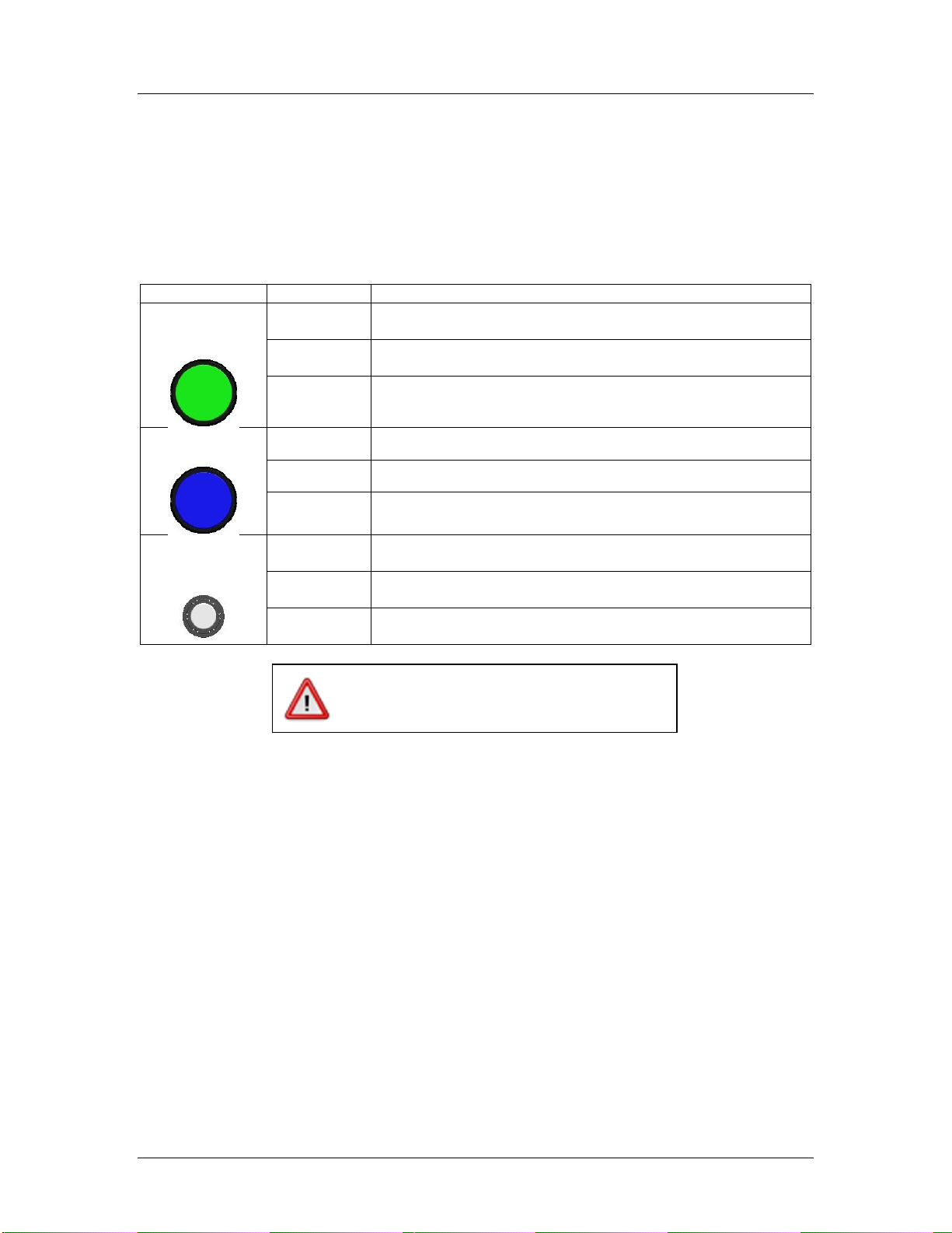
Each rotary adjustment knob on the Operator Interface performs a different function when
applying material. See the table below.
Input
Input
Function
Green
SPREADER
Knob
Twist Left
Decrease the granular set rate.
Twist Right
Increase the granular set rate.
Pushbutton
Place the system in standby.
Remove the system from standby.
Blue SPINNER
Knob
Twist Left
Decrease the spinner set rate.
Twist Right
Increase the spinner set rate.
Pushbutton
Blast the active material(s).
Cancel Blast.
Gray LIQUID
Knob
Twist Left
Decrease the liquid set rate, if enabled.
Twist Right
Increase the liquid set rate, if enabled.
Pushbutton
Turn on or off the liquid application, if enabled.
To spread granular material:
STEP 1: Twist the SPREADER knob to adjust your granular output percentage.
STEP 2: Twist the SPINNER knob to adjust your spinner set rate.
STEP 3: Press the SPREADER knob to remove the spreader control from standby.
Granular material will spread depending on the state of the ground speed
interrupt calibration setting and if the vehicle is detecting ground speed.
STEP 4: Press the SPREADER knob to place the spreader control back in standby and
stop the outputs.
To reduce the risk of death or injury, ensure
that all personnel are clear from moving
machinery before activating outputs.

SSC3100 Operation & Calibration Manual
Applying Material
5
To spread granular and prewet material:
STEP 1: Press the gray LIQUID knob to activate the prewet application. This will
illuminate the selected prewet application percentage next to the LIQUID dial.
STEP 2: Twist the SPREADER knob to adjust your granular output percentage.
STEP 3: Twist the SPINNER knob to adjust your spinner set rate.
STEP 4: Twist the LIQUID knob to adjust the prewet output percentage.
STEP 5: Press the SPREADER knob to remove the spreader control from standby.
Granular and prewet material will spread depending on the state of the ground
speed interrupt calibration setting and if the vehicle is detecting ground speed.
STEP 6: Press the SPREADER knob to place the spreader control back in standby and
stop the outputs.
To spread direct liquid material:
STEP 1: Turn the SPREADER and SPINNER dials to 0.
STEP 2: Press the gray LIQUID knob to activate the liquid application. This will illuminate
the selected liquid application percentage next to the LIQUID dial.
STEP 3: Twist the LIQUID knob to adjust the direct output percentage.
STEP 4: Press the SPREADER knob to remove the spreader control from standby. The
liquid material will spread depending on the state of the ground speed interrupt
calibration setting and if the vehicle is detecting ground speed.
STEP 5: Press the SPREADER knob to place the spreader control back in standby and
stop the outputs.
To reduce the risk of death or injury, ensure
that all personnel are clear from moving
machinery before activating outputs.
This application mode is only applicable when
the liquid mode is set to one of the three prewet
related modes in calibration.
This application mode is only applicable when
the liquid mode is set to one of the two direct
liquid related modes in calibration.

SSC6100 Operation Manual
Applying Material - Blast
6
Blast
Blast is a spreader feature that runs the applicable output at the maximum percentage for a set
amount of time. By default, Blast is set to spread for ten seconds.
When Blast is activated, the BLAST LED will illuminate RED.
To activate Blast:
STEP 1: Press the Blue SPINNER Knob on the Operator Interface. The system will blast
for its configured amount of time. The Blast feature works whether or not the
system is in standby or the vehicle is moving.
To deactivate Blast before it automatically shuts off:
STEP 1: While the system is Blasting, press the Blue SPINNER Knob on the Operator
Interface. The Blast feature will shut off and return to its previous operation
(spreading or standby).
To reduce the risk of death or injury, ensure
that all personnel are clear from moving
machinery before activating outputs.
When blast mode is activated, blast rates will
only be applied to outputs with application rates
currently not set to zero.
NOTE: Blast mode does not affect the spinner
output.
SSC3100 Operation & Calibration Manual
Unload
7
Unload
The Unload mode allows you to unload materials from the vehicle. This mode is only necessary if
the system is setup to have the ground speed interrupt enabled. The mode is cancelled by
placing the system into standby.
Each rotary adjustment knob on the Operator Interface performs a different function when
unloading material. See the table below.
Input
Action
Function
Green
SPREADER
Knob
Twist Left
Decrease the granular output percentage.
Twist Right
Increase the granular output percentage.
Pushbutton
Stop unloading material.
Blue SPINNER
Knob
Twist Left
Decrease the spinner output percentage. (If available)
Twist Right
Increase the spinner output percentage. (If available)
Pushbutton
None
Gray LIQUID
Knob
Twist Left
Decrease the liquid output percentage.
Twist Right
Increase the liquid output percentage
Pushbutton
Turn on or off the liquid output.
When unload mode is active the ACTIVE LED and BLAST LED will illuminate red. The output
rates for the granular, spinner or liquid will be reflected by the illuminated numbers around the
corresponding dials.
To unload granular material:
STEP 1: Ensure that the system is in standby and the vehicle is not moving.
STEP 2: Turn off the liquid output if it is active by pressing the liquid button.
STEP 3: Press and hold the blue SPINNER knob.
STEP 4: Press the green SPREADER knob, the ACTIVE LED and the BLAST LED will
change to red, you can then release the blue SPINNER knob and the green
SPREADER knob.
STEP 5: Use the green SPREADER knob to adjust the granular output percentage, it will
start out at the maximum rate.
STEP 6: Use the blue SPINNER knob to adjust the spinner output percentage.
STEP 7: Press the green SPREADER knob to finish unloading granular material.
To reduce the risk of death or injury, ensure
that all personnel are clear from moving
machinery before activating outputs.

SSC3100 Operation & Calibration Manual
Unload
8
To unload liquid material:
STEP 1: Ensure that the system is in standby and the vehicle is not moving.
STEP 2: Turn the SPREADER and SPINNER dials to 0.
STEP 3: Turn on the liquid output if it is not already on.
STEP 4: Press and hold the blue SPINNER knob.
STEP 5: Press the green SPREADER knob, the ACTIVE LED and the BLAST LED will
change to red, you can then release the blue SPINNER knob and the green
SPREADER knob.
STEP 6: Use the gray LIQUID knob to adjust the liquid output percentage, it will start out
at the maximum rate.
STEP 7: Press the green SPREADER knob to stop unloading liquid material.

SSC3100 Operation & Calibration Manual
Calibration
9
Calibration
The Calibration feature is used to setup your FORCE America SS3100 for your system and
application requirements. When the calibration feature is active the blast indicator on the front of
the unit will be illuminated green.
To activate the Calibration Feature:
1. Set the SPREADER and SPINNER set rates to 0.
2. While the system is in Standby, press and hold the liquid button for three seconds.
3. Once the system activates the calibration feature indicated by the blast indicator on the
front panel turning green, release the liquid button.
To exit the Calibration Feature:
1. Press and hold the liquid button for three seconds.
When the calibration feature is active, the buttons have the following functions:
Input
Input
Function
Green
SPREADER
Knob
Twist Left
Adjust the value for the active calibration setting.
Twist Right
Adjust the value for the active calibration setting.
Pushbutton
Place the system in standby.
Remove the system from standby.
Blue
SPINNER
Knob
Twist Left
Decreases the value for the active calibration setting when
setting the min or max duty cycle.
Twist Right
Increases the value for the active calibration setting when setting
the min or max duty cycle.
Pushbutton
None.
Gray
LIQUID
Knob
Twist Left
Select the previous calibration setting for adjustment.
Twist Right
Select the next calibration setting for adjustment
Pushbutton
Exits the calibration menu when held for 3 seconds when the
system is in standby.
The particular calibration setting being modified along with its current value will be indicated through
the various illuminated LEDs on the panel which is explained in the following section, Description
of Calibration Values.
SSC3100 Operation & Calibration Manual
Description of Calibration Values
10
Description of Calibration Values
The numbers located around the liquid dial will be used to indicate which calibration setting is active
and the numbers located around the spreader and spinner dials will indicate the selected value for
that setting. Rotating the liquid dial will adjust which calibration setting is currently being displayed
and changed. Rotating the spreader dial will adjust the setting for the selected calibration item.
The calibration settings will follow the order listed below. The initial value upon entering calibration
will be the spreader min output.
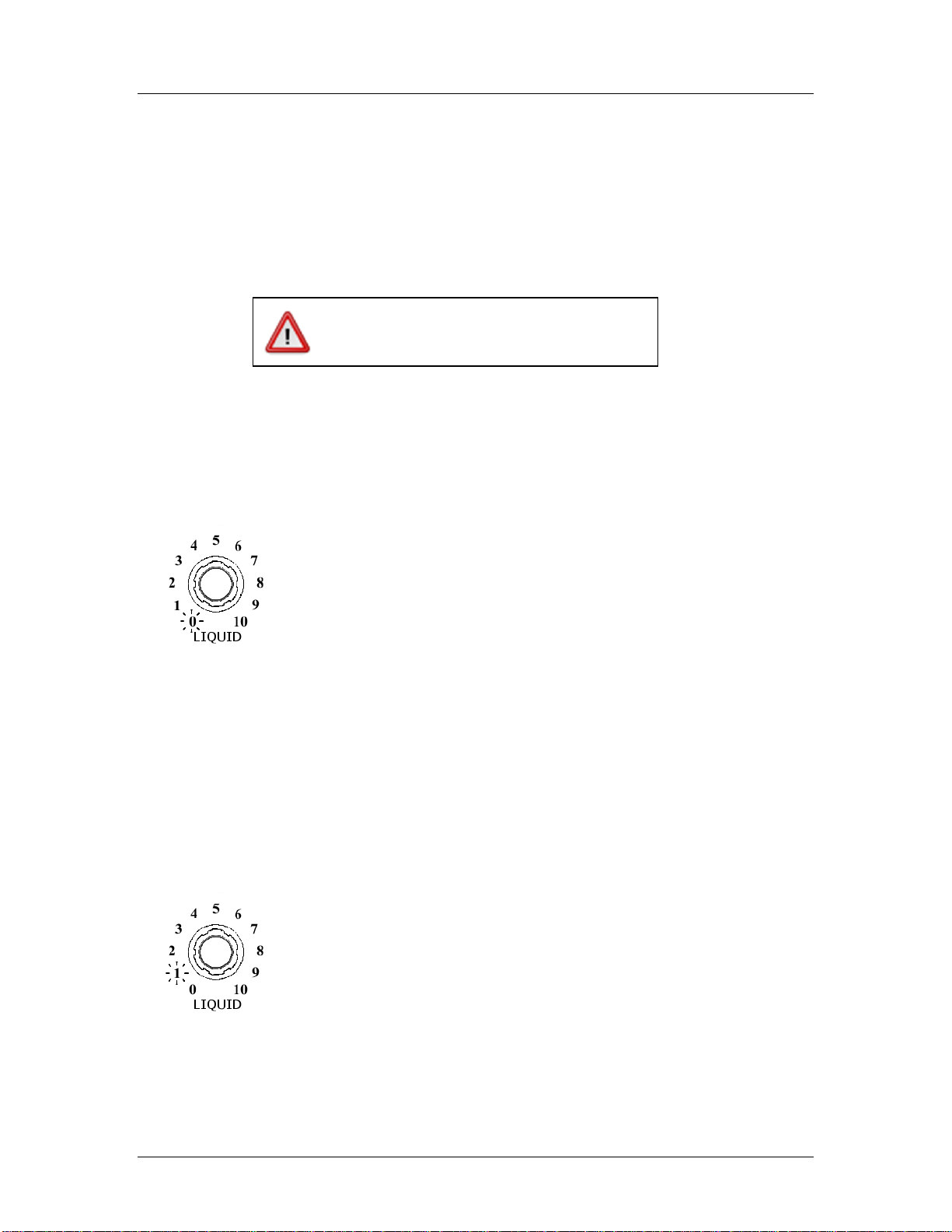
Spreader Min Output
The Spreader Min Output item sets the duty cycle required to turn the auger
at its slowest rate. The setting is indicated by having the LIQUID dial
illuminated at 0. The value is indicated by illuminating the numbers around
the SPREADER and SPINNER dials. The highest number illuminated
around the SPREADER dial indicates the tens position for the duty cycle
and the highest number illuminated around the SPINNER dial indicates the
ones position. The default value is 20% and is represented by having the
0, 1, and 2 numbers illuminated around the SPREADER dial and the 0
number illuminated around the SPINNER dial.
Use the green SPREADER knob to activate/deactivate the output to test
the auger speed when adjusting the Min Output value. The ACTIVE LED
will illuminate green when the spreader control is out of standby and
running the output. Rotating the SPREADER knob will increase/decrease
the duty cycle by 10% and using the SPINNER knob will increase/decrease
the duty cycle by 1%.
Spreader Max Output
The Spreader Max Output item sets the duty cycle required to turn the
auger at its fastest rate. The setting is indicated by having the LIQUID dial
illuminated at 1. The value is indicated by illuminating the numbers around
the SPREADER and SPINNER dials. The highest number illuminated
around the SPREADER dial indicates the tens position for the duty cycle
and the highest number illuminated around the SPINNER dial indicates the
ones position. The default value is 75% and is represented by having the
numbers 0 thru 7 illuminated around the SPREADER dial and the numbers
0 thru 5 illuminated around the SPINNER dial.
Use the green SPREADER knob to activate/deactivate the output to test
the auger speed when adjusting the Max Output value. The ACTIVE LED
will illuminate green when the spreader control is out of standby and
running the output. Rotating the SPREADER knob will increase/decrease
the duty cycle by 10% and using the SPINNER knob will increase/decrease
the duty cycle by 1%.
To reduce the risk of death or injury, ensure
that all personnel are clear from moving
machinery before activating outputs.

SSC3100 Operation & Calibration Manual
Description of Calibration Values
11
Spinner Min Output
The Spinner Min Output item sets the duty cycle required to turn the spinner
at its slowest rate. The setting is indicated by having the LIQUID dial
illuminated at 2. The value is indicated illuminating the numbers around
the SPREADER and SPINNER dials. The highest number illuminated
around the SPREADER dial indicates the tens position for the duty cycle
and the highest number illuminated around the SPINNER dial indicates the
ones position. The default value is 20% and is represented by having the
0, 1, and 2 numbers illuminated around the SPREADER dial and the 0
number illuminated around the SPINNER dial.
Use the green SPREADER knob to activate/deactivate the output to test
the spinner speed when adjusting the Min Output value. The ACTIVE LED
will illuminate green when the spreader control is out of standby and
running the output. Rotating the SPREADER knob will increase/decrease
the duty cycle by 10% and using the SPINNER knob will increase/decrease
the duty cycle by 1%.
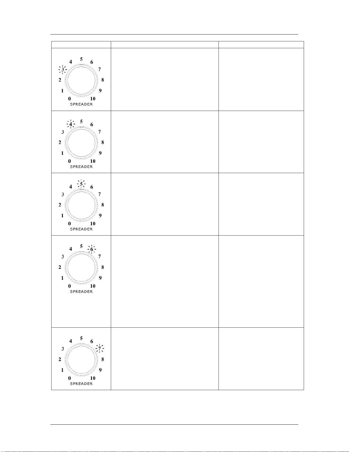
Spinner Max Output
The Spinner Max Output item sets the duty cycle required to turn the
spinner at its fastest rate. The setting is indicated by having the LIQUID dial
illuminated at 3. The value is indicated by illuminating the numbers around
the SPREADER and SPINNER dials. The highest number illuminated
around the SPREADER dial indicates the tens position for the duty cycle
and the highest number illuminated around the SPINNER dial indicates the
ones position. The default value is 75% and is represented by having the
numbers 0 thru 7 illuminated around the SPREADER dial and the numbers
0 thru 5 illuminated around the SPINNER dial.
Use the green SPREADER knob to activate/deactivate the output to test
the spinner speed when adjusting the Max Output value. The ACTIVE LED
will illuminate green when the spreader control is out of standby and
running the output. Rotating the SPREADER knob will increase/decrease
the duty cycle by 10% and using the SPINNER knob will increase/decrease
the duty cycle by 1%.
Liquid Min Output
The Liquid Min Output item sets the duty cycle required to turn the liquid
pump at its slowest rate. The setting is indicated by having the LIQUID dial
illuminated at 4. The value is indicated illuminating the numbers around
the SPREADER and SPINNER dials. The highest number illuminated
around the SPREADER dial indicates the tens position for the duty cycle
and the highest number illuminated around the SPINNER dial indicates the
ones position. The default value is 20% and is represented by having the
0, 1, and 2 numbers illuminated around the SPREADER dial and the 0
number illuminated around the SPINNER dial.

SSC3100 Operation & Calibration Manual
Description of Calibration Values
12
Use the green SPREADER knob to activate/deactivate the output to test
the liquid pump speed when adjusting the Min Output value. The ACTIVE
LED will illuminate green when the spreader control is out of standby and
running the output. Rotating the SPREADER knob will increase/decrease
the duty cycle by 10% and using the SPINNER knob will increase/decrease
the duty cycle by 1%.
Liquid Max Duty Cycle
The Liquid Max Output item sets the duty cycle required to turn the liquid
pump at its fastest rate. The setting is indicated by having the LIQUID dial
illuminated at 5. The value is indicated by illuminating the numbers around
the SPREADER and SPINNER dials. The highest number illuminated
around the SPREADER dial indicates the tens position for the duty cycle
and the highest number illuminated around the SPINNER dial indicates the
ones position. The default value is 75% and is represented by having the
numbers 0 thru 7 illuminated around the SPREADER dial and the numbers
0 thru 5 illuminated around the SPINNER dial.
Use the green SPREADER knob to activate/deactivate the output to test
the liquid pump speed when adjusting the Max Output value. The ACTIVE
LED will illuminate green when the spreader control is out of standby and
running the output. Rotating the SPREADER knob will increase/decrease
the duty cycle by 10% and using the SPINNER knob will increase/decrease
the duty cycle by 1%.
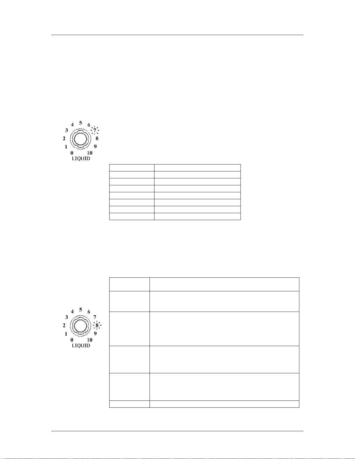
Blast Time
The Blast Time item sets the amount of time in seconds that the blast mode
will run once the blue Blast Knob has been pressed and released. The
setting is indicated by having the liquid dial illuminated at 6. The value is
indicated by the numbers around the spreader dial and the table below.
The default value is 10 seconds.
Spreader
Dial
Time Setting
0
Momentary
1
1 Second
2
2 Seconds
3
3 Seconds
4
4 Seconds
5
5 Seconds
6
6 Seconds
7
7 Seconds
8
8 Seconds
9
9 Seconds
10
10 Seconds
SSC3100 Operation & Calibration Manual
Description of Calibration Values
13
Speedometer Configuration
The speedometer configuration item is used to enable the ground speed
interrupt. When the ground speed interrupt is enabled, the system will stop
spreading material when the vehicle is not moving. If ground speed
interrupt is to be enabled the proper speedometer signal type and input
pulse range needs to be selected. The system supports an electronic or
mechanical signal with a low pulse rate or high pulse rate. If the vehicles
pulses per mile is higher than 20,000 (pulses per kilometer is higher than
12,500) select the high pulse rate otherwise select the low pulse rate. The
setting is indicated by having the liquid dial illuminated at 7. The value is
indicated by the numbers around the spreader dial and the table below.
The default value is Disabled.
*When this calibration item is active, spreader dial position 10 will illuminate
in addition to the setting value when the system is detecting a speedometer
signal.
Spreader Dial
State
0
Disabled
1
Electronic –Low Pulse Rate
2
Electronic –High Pulse Rate
3
Mechanical –Low Pulse Rate
4
Mechanical –High Pulse Rate
*10
Signal Present
Liquid Mode
The liquid mode item determines how the liquid output on the controller will
operate. The setting is indicated by having the liquid dial illuminated at 8.
The value is indicated by the number around the spreader dial and the table
below. The default value is Disabled.
Spreader
Dial
Description
0
Disabled
The liquid output will not run regardless of the
system state
1
Gravity Prewet
The liquid output will function as an on/off output
used to operate a ball valve. The output will
only be active when the granular output is
active.
2
Prewet (No Liquid Blast)
The liquid output will only operate when the
granular output is active and the output rate will
not change when the blast feature is active.
3
Prewet (Liquid Output Blasts)
The liquid output will only operate when the
granular output is active and the output rate will
increase to the max setting when blast is active.
4
Direct (No Liquid Blast)

SSC3100 Operation & Calibration Manual
Description of Calibration Values
14
The liquid output will run independent of the
granular output allowing the liquid to be active
when the granular rate is 0. In this mode the
liquid output will not change when the blast
feature is active.
5
Direct (Liquid Output Blasts)
The liquid output will run independent of the
granular output allowing the liquid to be active
when the granular rate is 0. In this mode the
liquid output will increase to the max setting
when blast is active.
Aux Output Configuration
The Aux Output Configuration will determine the operation of the output
associated with the loose wire labeled AUX in the harness. The setting is
indicated by having the liquid dial illuminated at 9. The value is indicated
by the numbers around the spreader dial and the table below. The default
value is None.
Spreader
Dial
Description
0
None/Off
The aux output does nothing and will be off.
1
Auger On
The aux output will be on when the auger is
running.
2
Liquid On
The aux output will be on when the liquid output
is active.
Restore Defaults
The Restore Defaults item allows for the resetting of all calibration settings
to factory default settings. The setting is indicated by having the 0 and 10
illuminated around the liquid dial.
To restore the calibration settings, press and release the spreader dial then
press and release the spinner dial.
Firmware Version
The firmware version item allows for the determination of the systems
firmware (software) version. The setting is indicated by having the 1 and
10 illuminated around the liquid dial.
The number indicated by the spreader dial indicates the major number and
the number indicated by the spinner dial indicates the minor number.
(Version = Major Number.Minor Number)

SSC3100 Operation & Calibration Manual
Troubleshooting and Error Conditions
15
Troubleshooting and Error Conditions
When the system encounters an error condition the ACTIVE LED and BLAST LED will alternately
flash RED to indicate that an error was detected. The information related to the error will be
indicated using the numbers around the SPREADER dial by illuminating the number of the error.
The following table can be used to determine the active error, what conditions caused it to occur
and any recommended actions that can be taken to resolve the error.
Pressing the liquid dial will acknowledge the error condition and either advance the indicator to
the next error condition or if no more errors are active place the system into normal operation
mode. Stuck input errors and the valve power error cannot be acknowledged and will remain
active until resolved.
System Status
Condition
Recommended Action
Unstable Voltage Detected
The system is detecting an unstable
voltage input on the constant power
wire during startup.
Verify that the voltage input for
the constant power connection
is stable and above 8 volts.
Stuck Spreader Knob
The green SPREADER knob was
pressed during startup.
Verify that the green
SPREADER knob is not
pressed. This error condition
cannot be acknowledged and
will remain active until cleared.
Stuck Spinner Knob
The blue SPINNER knob was pressed
during startup.
Verify that the blue SPINNER
knob is not pressed. This error
condition cannot be
acknowledged and will remain
active until cleared.
Stuck Liquid Knob
The gray LIQUID knob was pressed
during startup.
Verify that the gray LIQUID
knob is not pressed. This error
condition cannot be
acknowledged and will remain
active until cleared.
SSC3100 Operation & Calibration Manual
Troubleshooting and Error Conditions
16
System Status
Condition
Recommended Action
Fused Power Missing
The system is not detecting power on
the fused circuit which is used to run the
valve outputs.
Verify that the fuse is not
blown, if it is blown replace
with a 10 Amp
Stuck Remote Standby
The remote standby input was active
during startup.
Verify that the remote standby
input is not grounded.
Stuck Remote Blast
The remote blast input was active
during startup.
Verify that the remote blast
input is not grounded.
Improper Shutdown
The system detected an improper
shutdown caused by losing constant
power before the system completed its
shutdown process.
Verify that the dashkey wire is
properly connected to a
dashkey signal.
Verify that the constant power
wire is properly connected to a
voltage source that receives
constant power.
Verify that the voltage input for
the constant power connection
is stable and above 8 volts.
Corrupt calibration settings
The system detected an issue with the
stored calibration data. The calibration
data has been reset to the factory
defaults.
When calibrating the system
make sure to exit the
calibration menu before turning
off the spreader control.
Table of contents


