Force Flow SOLO 1000 Guide

INSTALLATION&OPERATION
electroniccylinderscale
1-or2-channelindicator
factorycalibrated
s/n__________________
1150-DBurnettAve,Concord,CA94520USA
1-800-893-6723Fax:925-686-6713
www.forceflow.com/Info@forceflow.com
Version:PRO96LCD
REF:T4\O&M\CYLSOLO\CVRCYLSO.tcw(O00a.pdf)
SOLO1000
FORCEFLOW
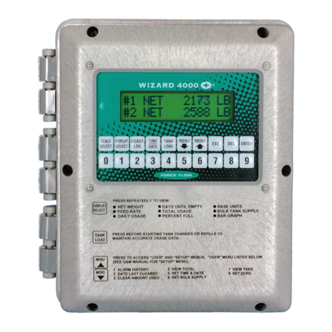
SOLO 1000
CHLOR-SCALE150
AMMONIA-SCALE
CYLINDER-SCALE
SOLO1000
7
INDICATOR:
ALLCYLINDERS
SCALE:
NET#1=175
NET#2=225
SOLO1000
NET=175
1-CHANNEL2-CHANNEL
7
J
J

INCLUDESMODELS:
1150-DBurnettAve,Concord,CA94520USA
1-800-893-6723US&Canada,Fax:925-686-6713
WWW.FORCEFLOW.COM/INFO@FORCEFLOW.COM
REF:T4\O&M\CYLSOLO\MODELNO.tcw(OOAa.pdf)
ELECTRONICfor
ALLCYLINDERS
SINGLEORDUALCYLINDER
withSOLO1000DIGITAL
1-AND2-CHANNELINDICATOR
FORCAPACITIES:
CHLOR-SCAL1150
150lbCYLINDERSforCHLORINE&SULFURDIOXIDE
400lbAMMONIACYLINDERS
&200lbLIQUEFIEDGASCYLINDERS
SingleCylinder
withSolo1000(SingleChannelIndicator)
DualCylinder
withSolo1000-2(DualChannelIndicator)
SR150
SR150-2
(Metric:SR68K68kg)
(Metric:SR68K-268kg)
AMMONIA-SCALESingleCylinder
withSolo1000(SingleChannelIndicator)
DualCylinder
withSolo1000-2(DualChannelIndicator)
SR400-AS
SR400-2AS
(Metric:SR200K-AS200kg)
(Metric:SR200K-2AS200kg)
CYLINDER-SCALESingleCylinder
withSolo1000(SingleChannelIndicator)
DualCylinder
withSolo1000-2(DualChannelIndicator)
SR200
SR200-2
(Metric:SR100K100kg)
(Metric:SR100K-2100kg)
FORCEFLOW

FORCEFLOW
HELPHOTLINE
1-800-893-6723
www.forceflow.com
info@forceflow.com
NOTES:

S.1.000
1150-DBurnettAve,Concord,CA94520USA
1-800-893-6723US&Canada,Fax:925-686-6713
www.forceflow.com/info@forceflow.com
REF:T4\O&M\INDEX\Y44.tcwetc(Y44.pdfetc)
SECTION
INSTALLATIONDRAWINGS
S.1.101-1.1
S.1.101-1.2
S.1.101-2.1
S.1.101-2.2
S.1.101-3.1
S.1.101-3.2
S.2.000SCALEOPERATION:
S.2.101ScaleOperation(Use"Portable"Applications)
S.3.000
SOLO1000IndicatorwithALLCYLINDERSCALES
INDEX
INSTALLATIONCHECKLISTS
S.1.301
S.1.305
1-CHANNEL:IndicatorWiring&PlumbingDrawing
2-CHANNEL:IndicatorWiringetc.
1-CHANNEL:Instructions:Power;LoadCell&TareAdjust;4-20mA
2-CHANNEL:Instructions:Poweretc.
1-CHANNEL:Instructions:SetPoint;Surge&StaticProtection
2-CHANNEL:Instructions:SetPointetc.
INDICATORINSTALLATION
S.1.201-1
S.1.201-2
S.1.202-1
S.1.202-2
S.1.203-1
S.1.203-2
InstallationCheckList
Start-UpCheckList
OPTIONALALARMSETPOINT:
S.2.301-1
S.2.301-2
1-CHANNELAlarmSetPointConfiguration
2-CHANNELAlarmSetPointConfiguration
MISCELLANEOUS:
S.3.105
S.3.401
Calibration(SlottedPlatformsONLY)
PartsList
YOU
ARE
HERE!
InstallationnDrawing
InstallationIntroduction
InstallationSteps1thru2
InstallationSteps3thru6a
InstallationSteps6bthru6f
InstallationSteps6gthru7
INSTALLATIONINSTRUCTIONS
S.1.102
S.1.103
S.1.104
S.1.105
S.1.106
S.1.107
Single200#(100kg)Cyl.Scale,SingleChannelDrawing
Dual200#(100kg)Cyl.Scale,DualChannelDrawing
Single400#(200kg)Cyl.Scale,SingleChannelDrawing
Dual400#(200kg)Cyl.Scale,DualChannelDrawing
Single150#(68kg)Cyl.Scale,SingleChannelDrawing
Dual150#(68kg)Cyl.Scale,DualChannelDrawing
FORCEFLOW

NET=150
CylinderBackstop
PlatformMountedLevel
15/8"(41mm)
SOLO1000
1-Channel
Indicator
39"to40"
(990mm-1016mm)
10"
(254mm)
Platform
SafetyChain
WallMounted
Chaining
Bracket
SpringLoaded
SnapHook
1150-DBurnettAve,Concord,CA94520USA
1-800-893-6723US&Canada,Fax:925-686-6713
www.forceflow.com/info@forceflow.com
Drawnby:SLP
Date:01/02/94
Revised:04/09/01
Scale:NONE
DrawingNumber
File:T4\O&M\CYLSOLO\150SOLO1.tcw(O01-1a.pdf)(WEB:150#SOL1.pdf)
30333
ELECTRONICCHLOR-SCALE150
WITHSOLO1000INDICATOR
FOR150#CYLINDERS
4-20mA
Output
131/2"
(343mm)
161/2"
(419mm)
181/2"
(470mm)
SOLO1000
S.1.101-1.1
SINGLECYLINDERSCALEwith
1-CHANNELINDICATOR
FORCEFLOW
FORCEFLOW
150LB.(68KG)CYLINDERS

NET=150
CylinderBackstop
PlatformMountedLevel
15/8"(41mm)
SOLO1000
1-Channel
Indicator
39"to40"
(990mm-1016mm)
10"
(254mm)
Platform
SafetyChain
WallMounted
Chaining
Bracket
SpringLoaded
SnapHook
1150-DBurnettAve,Concord,CA94520USA
1-800-893-6723US&Canada,Fax:925-686-6713
www.forceflow.com/info@forceflow.com
Drawnby:SLP
Date:01/15/96
Revised:08/16/02
Scale:NONE
DrawingNumber
File:T4\O&M\CYLSOLO\AMMSOLO1.tcw(O01-2a.pdf)
30448
ELECTRONICAMMONIA-CYLINDER
WITHSOLO1000INDICATOR
FOR400LB(200kg)CYLINDERS
4-20mA
Output
SOLO1000
S.1.101-2.1
SINGLECYLINDERSCALEwith
1-CHANNELINDICATOR
FORCEFLOW
FORCEFLOW
211/2"
(546mm)
183/4"
(476mm)
153/4"
(400mm)
CALIBRATION
RING
400LB.(200KG)AMMONIACYLINDERS

NET1=150
NET2=125
CylinderBackstop
PlatformMountedLevel
15/8"(41mm)
Electrical
Cable
SOLO1000
2-Channel
Indicator
39"to40"
(990mm-1016mm)
10"
(254mm)
Platform
SafetyChain
Wall
Mounted
Chaining
Bracket
SpringLoaded
SnapHook
1150-DBurnettAve,Concord,CA94520USA
1-800-893-6723US&Canada,Fax:925-686-6713
www.forceflow.com/info@forceflow.com
Drawnby:SLP
Date:01/02/94
Revised:04/09/01
Scale:NONE
DrawingNumber
File:T4\O&M\CYLSOLO\150SOLO2.tcw(O01-1b.pdf)(WEB:150#SO2.pdf)
30330
ELECTRONICCHLOR-SCALE150
WITHSOLO1000-2DUALCHANNELINDICATOR
FOR150#CYLINDERS
Scale2
Scale1
Channel2
Channel1
4-20mAOutput
(Channel1)
4-20mAOutput
(Channel2)
131/2"
(343mm)
161/2"
(419mm)
181/2"
(470mm)
FLOQUIPFORCEFLOWEQUIPMENT
SOLO1000
S.1.101-1.2
DUALCYLINDERSCALEwith
2-CHANNELINDICATOR
FORCEFLOW
FORCEFLOW
150LB.(68KG)CYLINDERS

NET1=150
NET2=125
CylinderBackstop
PlatformMountedLevel
15/8"(41mm)
Electrical
Cable
SOLO1000
2-Channel
Indicator
39"to40"
(990mm-1016mm)
10"
(254mm)
Platform
SafetyChain
Wall
Mounted
Chaining
Bracket
SpringLoaded
SnapHook
1150-DBurnettAve,Concord,CA94520USA
1-800-893-6723US&Canada,Fax:925-686-6713
www.forceflow.com/info@forceflow.com
Drawnby:SLP
Date:01/02/94
Revised:08/16/02
Scale:NONE
DrawingNumber
File:T4\O&M\CYLSOLO\150SOLO2.tcw(O01-2b.pdf)(WEB:AMM#SO2.pdf)
30449
ELECTRONICAMMONIA-SCALE
WITHSOLO1000-2DUALCHANNELINDICATOR
FOR400#(200kg)CYLINDERS
Scale2
Scale1
Channel2
Channel1
4-20mAOutput
(Channel1)
4-20mAOutput
(Channel2)
FLOQUIPFORCEFLOWEQUIPMENT
SOLO1000
S.1.101-2.2
DUALCYLINDERSCALEwith
2-CHANNELINDICATOR
FORCEFLOW
FORCEFLOW
400LB.(200KG)CYLINDERS
211/2"
(546mm)
183/4"
(476mm)
153/4"
(400mm)
CALIBRATION
RING

NET=150
CylinderBackstop
PlatformMountedLevel
15/8"(41mm)
SOLO1000
1-Channel
Indicator
39"to40"
(990mm-1016mm)
10"
(254mm)
Platform
SafetyChain
WallMounted
Chaining
Bracket
SpringLoaded
SnapHook
1150-DBurnettAve,Concord,CA94520USA
1-800-893-6723US&Canada,Fax:925-686-6713
www.forceflow.com/info@forceflow.com
Drawnby:SLP
Date:08/17/02
Revised:
Scale:NONE
DrawingNumber
File:T4\O&M\CYLSOLO\CYLSOLO1.tcw(O01-3a.pdf)
30450
ELECTRONICCYLINDERSCALE
WITHSOLO1000INDICATOR
FOR200LB(100kg)CYLINDERS
4-20mA
Output
SOLO1000
S.1.101-3.1
SINGLECYLINDERSCALEwith
1-CHANNELINDICATOR
FORCEFLOW
FORCEFLOW
200LB.(100K)CYLINDERS
131/2"
(343mm)
161/2"
(419mm)
181/2"
(470mm)

NET1=150
NET2=125
CylinderBackstop
PlatformMountedLevel
15/8"(41mm)
Electrical
Cable
SOLO1000
2-Channel
Indicator
39"to40"
(990mm-1016mm)
10"
(254mm)
Platform
SafetyChain
Wall
Mounted
Chaining
Bracket
SpringLoaded
SnapHook
1150-DBurnettAve,Concord,CA94520USA
1-800-893-6723US&Canada,Fax:925-686-6713
www.forceflow.com/info@forceflow.com
Drawnby:SLP
Date:01/02/94
Revised:08/16/02
Scale:NONE
DrawingNumber
File:T4\O&M\CYLSOLO\200SOLO2.tcw(O01-3b.pdf)(WEB:AMM#SO2.pdf)
30451
ELECTRONICCYLINDERSCALE
WITHSOLO1000-2DUALCHANNELINDICATOR
FOR200#(100kg)CYLINDERS
Scale2
Scale1
Channel2
Channel1
4-20mAOutput
(Channel1)
4-20mAOutput
(Channel2)
FLOQUIPFORCEFLOWEQUIPMENT
SOLO1000
S.1.101-3.2
DUALCYLINDERSCALEwith
2-CHANNELINDICATOR
FORCEFLOW
FORCEFLOW
200LB.(100KG)CYLINDERS
131/2"
(343mm)
161/2"
(419mm)
181/2"
(470mm)

FORCEFLOW
HELPHOTLINE
1-800-893-6723
www.forceflow.com
info@forceflow.com
NOTES:

S.1.000
1150-DBurnettAve,Concord,CA94520USA
1-800-893-6723US&Canada,Fax:925-686-6713
www.forceflow.com/info@forceflow.com
REF:T4\O&M\INDEX\Y44.tcwetc(Y44.pdfetc)
SECTION
INSTALLATIONDRAWINGS
S.1.101-1.1
S.1.101-1.2
S.1.101-2.1
S.1.101-2.2
S.1.101-3.1
S.1.101-3.2
S.2.000SCALEOPERATION:
S.2.101ScaleOperation(Use"Portable"Applications)
S.3.000
SOLO1000IndicatorwithALLCYLINDERSCALES
INDEX
INSTALLATIONCHECKLISTS
S.1.301
S.1.305
1-CHANNEL:IndicatorWiring&PlumbingDrawing
2-CHANNEL:IndicatorWiringetc.
1-CHANNEL:Instructions:Power;LoadCell&TareAdjust;4-20mA
2-CHANNEL:Instructions:Poweretc.
1-CHANNEL:Instructions:SetPoint;Surge&StaticProtection
2-CHANNEL:Instructions:SetPointetc.
INDICATORINSTALLATION
S.1.201-1
S.1.201-2
S.1.202-1
S.1.202-2
S.1.203-1
S.1.203-2
InstallationCheckList
Start-UpCheckList
OPTIONALALARMSETPOINT:
S.2.301-1
S.2.301-2
1-CHANNELAlarmSetPointConfiguration
2-CHANNELAlarmSetPointConfiguration
MISCELLANEOUS:
S.3.105
S.3.401
Calibration(SlottedPlatformsONLY)
PartsList
YOU
ARE
HERE!
InstallationnDrawing
InstallationIntroduction
InstallationSteps1thru2
InstallationSteps3thru6a
InstallationSteps6bthru6f
InstallationSteps6gthru7
INSTALLATIONINSTRUCTIONS
S.1.102
S.1.103
S.1.104
S.1.105
S.1.106
S.1.107
Single200#(100kg)Cyl.Scale,SingleChannelDrawing
Dual200#(100kg)Cyl.Scale,DualChannelDrawing
Single400#(200kg)Cyl.Scale,SingleChannelDrawing
Dual400#(200kg)Cyl.Scale,DualChannelDrawing
Single150#(68kg)Cyl.Scale,SingleChannelDrawing
Dual150#(68kg)Cyl.Scale,DualChannelDrawing
FORCEFLOW

IMPORTANT:ReadInstallation
Instructionsthoroughlybefore
installing.
5
1
6
4
3
7
2
1"(25mm)
to2"(51mm)
29966
1150-DBurnettAve,Concord,CA94520USA
1-800-893-6723US&Canada,Fax:925-686-6713
www.forceflow.com/info@forceflow.com
Drawnby:SLP
Date:02/15/93
Revised:04/24/97
Scale:NONE
DrawingNumber
File:T4\O&M\CYLWIZ\150WIZ1.tcw(K02.pdf)
CHLOR-SCALE150
For150lb.Chlorine&SO2Cylinders
ElectronicScales
FORCEFLOW
W.1.102
S.1.102
2
WIZARDorSOLO1000Indicators
AllCYLINDERApplications

INSTALLATION.OPERATION.MAINTENANCE
Two(2)AdjustableWrenches
ScrewDriverandTapeMeasure
Hammer(forpoundinginanchorbolts)
Cylinder(foraligningplatform)
CylinderChange-OutToolHooks
Topreventpossiblepersonalinjuryordamagetotheequipment
throughmisuse,thisequipmentshouldbeinstalled,operatedand
servicedonlybytrained,qualifiedpersonnelwhoarethoroughlyfamiliarwiththe
entirecontentsofthisInstructionManual,whichshouldbethoroughlyreviewedand
understoodpriortoinstallingandoperatingtheequipment.
havebeenaddedtotheChainingBracket
tokeepfrequentlyusedtools
neededto
change
cylinders.
PowerDrillandDrillBits
HammerDrillandMasonryBit(5/16")
Two(2)1/4"DiameterAnchors(forplatform)
Two(2)properlychosenAnchors(ChainingBracket)
Four(4)properlychosenAnchors(WizardorSolo)
YourElectronicCYLINDERScaleconsistsof
3basicassemblies:
1.LoadCellSystem(LoadCell,Cableand
WizardorSoloIndicator)
2.PVCPlatform(Backstop,Platform
withHingeandlevelingshims)
3.ChainingDevice(BracketwithEquipment
Hooks,ChainandSpringLoadedBoltSnap)
ITEMSREQUIREDFORINSTALLATION:
WARNING:
COMMENTS:
ElectronicScaleALLCYLINDERSwithSOLOINDICATOR
Ifyouhaveanyquestionsregardingtheinstallation,operationormaintenanceonyour
CYLINDERScaleorpleasedonothesitatetocallour....HELPHOTLINE1-800-893-6723.
1150-DBurnettAve,Concord,CA94520USA
1-800-893-6723US&Canada,Fax:925-686-6713
www.forceflow.com/info@forceflow.com
File:T4\O&M\CYLELE\150WIZA.tcw(K03.pdf)
FORCEFLOW
W.1.103
S.1.103

(B)
A)Placetheplatformonthefloorwiththebackstopsideoftheplatformatthewall.
NOTE:Allowatleast1"clearancebetweenwallandplatform.
DONOTANCHORPLATFORMTOFLOORUNTILSTEP4.
(A)Thechainingbracketshouldbeatapproximately
3/4theheightofthecylinder.
STEP2:ALIGNINGANDMOUNTINGTHECHAININGBRACKET
NOTE:IftheFootofyourwallprotrudes,itmaybenecessary
toputaspacerbetweenthewallandthechainingbracketto
assurenomorethan1"to2"spacebetweencylinderand
frontedgeofchainingbracket.(SeeInstallationDrawing
Step3and4).
CAUTION:Forproperoperationandtoavoidpossibledamagetothescaleorinjurytoyourself,youMUST
installtheseitemsinthefollowingStep-by-Stepmanner.ThestandardElectronicCHLOR-SCALE150is
meanttobeinstalledincloseproximitytoawallorotheruprightstructure.Ifthisisnotpossible,please
consultfactoryforproperinstallation.Eachofthesescalesisdesignedtoaccomodateaspecificcylinder
only(consultfactoryifyouareindoubt).SeedrawingsinSections1.101.1thru1.101.3.Removeallitems
frombox.Theloadcellsystemiswiredandcalibratedatthefactory.
INSTALLATIONNOTES:
(B)Toalignthechainingbracketwiththeplatform,adjustbracket
untilthehangingchainalignswiththeright-handsideofthe
backstop.Besurethebracketislevel,markholesandanchor
thebrackettothewall.Makesureyouranchorboltsare
properlysizedandarecompatiblewithyourwallmaterial!!
3/4oftheCylinderHeight
(A)
STEP1:PLACEPLATFORMONFLOOR
1150-DBurnettAve,Concord,CA94520USA
1-800-893-6723US&Canada,Fax:925-686-6713
www.forceflow.com/info@forceflow.com
File:T4\O&M\CYLWIZ\WIZ150B.tcw(K04.pdf)1/24/02BD
FORCEFLOW
W.1.104
S.1.104
1"CLEARANCEBETWEEN
PLATFORMANDWALL
PLATFORM
WALL
PLATFORM
(B)
B)FORALLIGNMENTPURPOSESONLY:
(A)
TEMPORARILY
UPSIDEDOWN
LOADCELL
TemporarilyplaceLoadCellUPSIDEDOWN
withstudthroughholeofplatform.

1"to2"
Adjusttheplatformdistancesothatwitha150lb.
cylinderagainsttheplatformbackstop,thecylinder
isapproximately1"to2"fromthefrontedgeofthe
chainingbracket.
CylinderMUSTNOTtouchchainingbracket
orscalewillnotoperateproperly.
Platformmustnottouchwallorscalewillnotfunction
properly.Markmountingholesonthefloor.Drillholes
with5/16"bitandboltscaletothefloorusingtwo(2)1/4"
diameteranchorbolts.Makesureyouranchorbolts
areproperlysizedandcompatiblewithyourfloormaterial!!
STEP3:ADJUSTINGCYLINDERDISTANCEFROMCHAININGBRACKET
Toavoidinjurycausedbytippingcylinder,DONOT
useuntilplatformisboltedtofloor.
STEP5:ANCHORINGTHELOADCELL
STEP4:ANCHORINGTHEPLATFORM
CAUTION:
(A)REMOVELOADCELL.UsingHOLEIN
PLATFORMastemplate,markfloorthrough
holetodrillLoadCellanchoringhole.
Usingthishole
tomarkfloorfor
loadcellanchoring.
1150-DBurnettAve,Concord,CA94520USA
1-800-893-6723US&Canada,Fax:925-686-6713
www.forceflow.com/info@forceflow.com
File:T4\O&M\CYLEWIZ\WIZ150C.tcw(K05.pdf)01/24/02BD
W.1.105
S.1.105
(B)Aftermarkisestablishedonthefloor,pivotPlatformoutoftheway.Centerpunchthe
marktoensureaccurateholelocation.Drilla5/16"holeusinganappropriatebit.
Drilltheholeapproximately1inchdeep.
Drill5/16"diameter
hole,1inchdeep.
FORCEFLOW

(C)Slidelevelingwasher(s)ifneededontostud,
sothatplatformislevelfronttorear.
(D)1.InsertLoadCellStudintohole
inthefloor.
2.BecertainthattheLoad
Cellisseated"flush"onthefloor.
3.PositionLoadCellsothatthecable
runsstraightouttoeithersideofthe
Platform.
Cabletoexitstraight
outoneithersideof
Platform.
(E)PivotPlatformbackintoplace.Sitethroughthe
mountingholeontheplatformtoensurethatthe
"BLACKDOT"ontheLoadCellbuttonis
centeredintheholeontheplatform.
Correct
Incorrect
(E)
(D3)
1150-DBurnettAve,Concord,CA94520USA
1-800-893-6723US&Canada,Fax:925-686-6713
www.forceflow.com/info@forceflow.com
File:T4\O&M\CYLWIZ\WIZ150D.tcw(K06.pdf)1/24/02BD
W.1.106
S.1.106
STEP5:ANCHORINGTHELOADCELLcont...
(D2)
(D1)
FORCEFLOW

To mount additional scales side-by-side, be sure
to allow for the frame hinge when determining the
distance between platforms (if minimizing floor
area) and repeat Step 1 - 7.
(F) If the "BLACK DOT" on the Load
Cell Button is not centered in the hole
on the platform loosen the floor anchor
bolts slightly and adjust platform as
needed. Once proper alignment is
achieved, tighten the anchor bolts.
Adjust platform for
proper alignment.
Loosen
"BLACK DOT" on
Load Cell should
be centered in hole
on platform.
1150-D Burnett Ave, Concord, CA 94520 USA
1-800-893-6723 US & Canada, Fax: 925-686-6713
File: T4\O&M\CYLWIZ\WIZ150E.tcw (K07.pdf) 1/24/02 BD
FORCE FLOW
FORCE FLOW
F
FL
LO
OQ
QI
I
U
UP
P
W.1.107
S.1.107
Check the platform-mounted level to assure that the
scale is level from FRONT to REAR. If the platform
is not level, either:
(A) RAISE REAR of platform by placing shim(s)
UNDERNEATH the LOAD CELL,
or (B) RAISE FRONT by placing shim(s)
UNDERNEATH the HINGE on the
ANCHOR BOLTS (shims provided with scale). (B)
LOAD CELL
FRONT
MOUNTING FOOT
PLATFORM
REAR
(A)
STEP 6: LEVEL PLATFORM
LEVELING
SHIMS
(if needed)
LEVELING
SHIMS
(if needed)
STEP 5: ANCHLORING LOAD CELL cont...
STEP 7: MOUNTING ADDITIONAL SCALES

FORCEFLOW
HELPHOTLINE
1-800-893-6723
www.forceflow.com
info@forceflow.com
NOTES:

FORCE FLOW
FORCE FLOW
F
FL
LO
OQ
QI
I
U
UP
P
S.1.000
1150-D Burnett Ave, Concord, CA 94520 USA
1-800-893-6723 US & Canada, Fax: 925-686-6713
REF: T4\O&M\INDEX\Y44.tcw etc (Y44.pdf etc)
SECTION
INSTALLATION DRAWINGS
S.1.101-1
S.1.101-2 Single Cylinder Scale, Single Channel Drawing
Dual Cylinder Scale, Dual Channel Drawing
S.2.000 SCALE OPERATION:
S.2.101 Scale Operation (Use "Portable" Applications)
S.3.000
SOLO 1000 Indicator with CHLOR-SCALE 150
INDEX
INSTALLATION CHECK LISTS
S.1.301
S.1.305
1-CHANNEL: Indicator Wiring & Plumbing Drawing
2-CHANNEL: Indicator Wiring etc.
1-CHANNEL: Instructions: Power; Load Cell & Tare Adjust; 4-20mA
2-CHANNEL: Instructions: Power etc.
1-CHANNEL: Instructions: Set Point; Surge & Static Protection
2-CHANNEL: Instructions: Set Point etc.
INDICATOR INSTALLATION
S.1.201-1
S.1.201-2
S.1.202-1
S.1.202-2
S.1.203-1
S.1.203-2
Installation Check List
Start-Up Check List
OPTIONAL ALARM SET POINT:
S.2.301-1
S.2.301-2 1-CHANNEL Alarm Set Point Configuration
2-CHANNEL Alarm Set Point Configuration
PARTS LIST:
S.3.401 Parts List
YOU
ARE
HERE !
Installationn Drawing
Installation Introduction
Installation Steps 1 thru 2
Installation Steps 3 thru 6a
Installation Steps 6b thru 6f
Installation Steps 6g thru 7
INSTALLATION INSTRUCTIONS
S.1.102
S.1.103
S.1.104
S.1.105
S.1.106
S.1.107
Other Force Flow Accessories manuals
