Force Flow WIZARD 4000 Manual
2430 Stanwell Dr, Concord, CA 94520 USA
1-800-893-6723 US & Canada, Fax: 925-686-6713
www.forceflow.com / info@forceflow.com
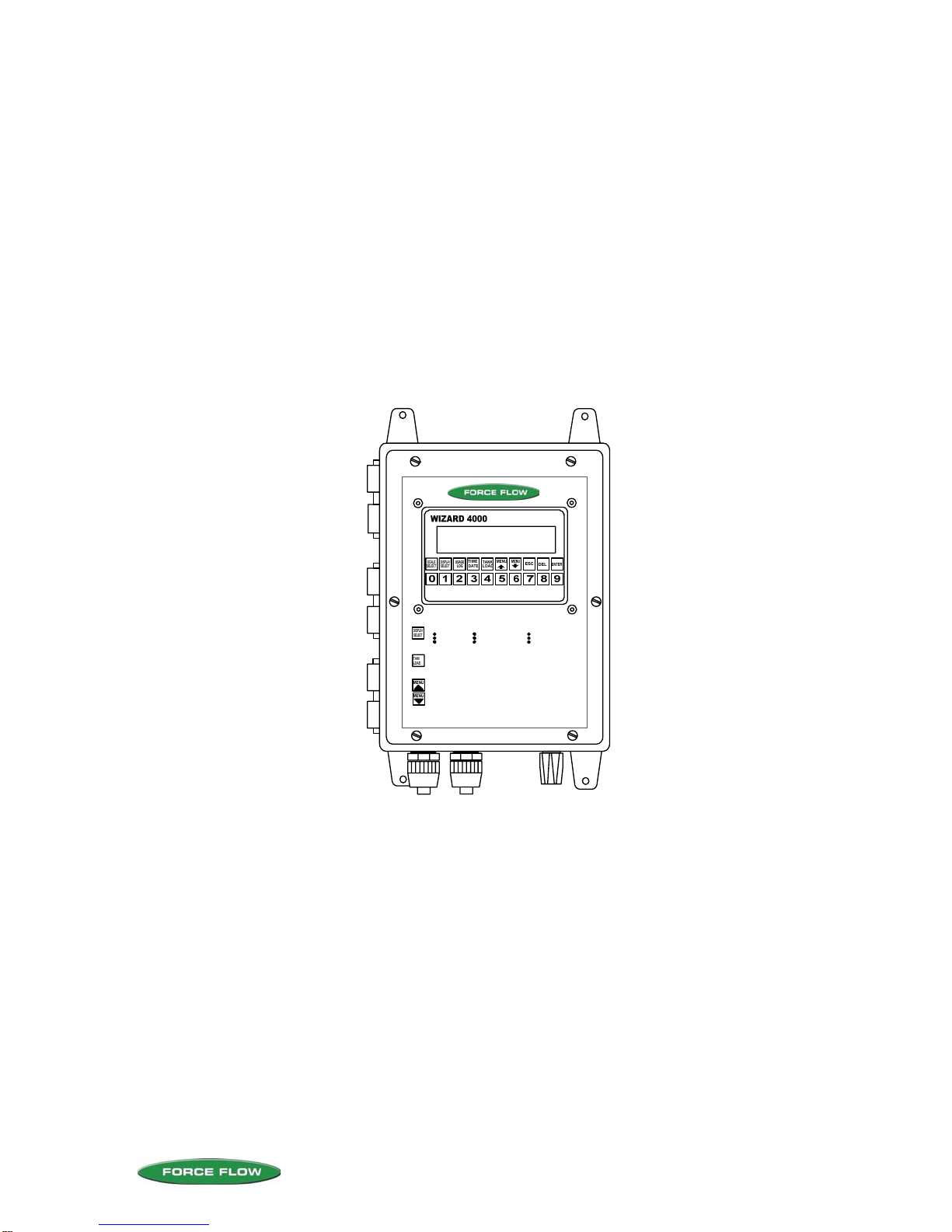
WIZARD 4000
DIGITAL WEIGHT INDICATOR
1 to 4 Channels
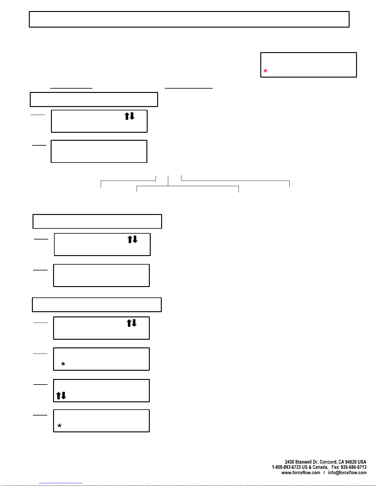
#3 NET 57.11 GL
#3 BULK 0.0 GL
PRESS REPEATEDLY TO VIEW:
NET WEIGHT
FEED RATE
DAILY USAGE
DAYS UNTIL EMPTY
TOTAL USAGE
PERCENT FULL
BASE UNITS
BULK TANK SUPPLY
BAR GRAPH
PRESS BEFORE STARTING TANK CHANGES OR REFILLS TO
MAINTAIN ACCURATE USAGE DATA.
ACCESS "USER" AND "SETUP" MENUS. "USER" MENU LISTED
BELOW (SEE O&M MANUAL FOR "SETUP" MENU).
1 ALARM HISTORY
2 DATE LAST CLEARED
3 CLEAR AMOUNT USED
4 VIEW TOTAL
5 SET TIME & DATE
6 VIEW BULK SUPPLY
7 VIEW TARE
8 DISPLAY UNITS
9 SET ZER
INSTALLATION, OPERATION
& MAINTENANCE

2430 Stanwell Dr, Concord, CA 94520 USA
1-800-893-6723 US & Canada, Fax: 925-686-6713
REF: T4\O&M\INDEX.\WIZ INDEX 2007.tcw
03/21/08 MT
SECTION II - WIZARD 4000 WEIGHT INDICATOR
INDEX
W.1
W.2
W.3
W.4
W.5
W.6
W.7
W.8
W.9
W.10
INDEX
INSTALLATION CHECKLIST
START-UP CHECKLIST
KEYBOARD QUICK REFERENCE GUIDE (Drawing 30835)
ELECTRONIC INDICATOR SPECS (Drawing 30831)
KEYPAD FUNCTIONS
TANK LOAD PROCEDURE (Drawing 30774)
HAZARDOUS LOCATION INSTALLATION (Drawing 29893)
WIRING INSTRUCTIONS (Drawing 29892)
MOTHERBOARD COMPONENT LAYOUT
W.11
W.12 POWER, LOAD CELL, 4-20mA SIGNALS
MODBUS, RELAYS, DISPLAY VIEW ANGLE
INSTALLATION & WIRING
W.13
W.14
W.15
1 ALARM HISTORY / 2 DATE LAST CLEARED / 3 CLEAR AMOUNT USED
4 VIEW TOTAL / 5 SET TIME & DATE / 6 SET BULK SUPPLY / 7 VIEW TARE
8 SET ZERO
USER MENU
W.16
W.17
W.18
W.19
W.20
W.21
W.22
W.23A
W.23B
1 DISPLAY FORMAT / 2 CHANNEL ID / 3 100 PERCENT
4 AUTO LOAD / 5 FILTER BAND / 6 MOTION BAND
7 SYSTEM TIME BASE
8 CONFIG. 4-20mA / 9 BULK SUPPLY / 10 AUTO REFILL
10 AUTO REFILL cont. / 11 SET ALARM VALUES / 12 ASSIGN RELAYS
12 ASSIGN RELAYS cont. / 13 USER PRIVILEGES / 14 DIAGNOSTICS
14 DIAGNOSTICS cont. / 15 FIELD CALIBRATION
15 FIELD CALIBRATION cont.
16 CONFIG TOTAL / 17 TANK SET UP
SETUP MENU
W.24
W.25
W.26
QUICK START GUIDE, DESCRIPTION, WIRING
SET VALUES, OVERFILL PROTECT., ARC CYCLE, PAUSE & PROJECT
AUTO REFILL CONTROL WIRING (Drawing 31172)
AUTO REFILL CONTROL (OPTIONAL)
W.27
W.28
W.29
CONFIGURATION, COMM., SET-UP, DEVICE ADDRESS
REGISTER MAP
SAMPLE DATA STRINGS
MODBUS SERIAL COMMUNICATIONS (OPTIONAL)
M.1 FACTORY WARRANTY & PERFORMANCE GUARANTEE
WARRANTY
W.1
W.30
W.31 RELAY WIRING FOR 1 TO 8 RELAYS (Drawing 31272)
RELAY WIRING FOR 9 TO 12 RELAYS (Drawing 31273)
RELAY WIRING

INSTALLATION CHECKLIST
QUESTIONS ? Help Hotline: 1-800-893-6723
W.2
File: T4\O&M\WIZ MSTR\WIZ PR328 INSTALL CHKLST.tcw
INSTALL SCALE PLATFORM(S), PROCELL(S) or ECHO-SCALE(S) in accordance with supplied
Operation & Maintenance Manual.
WIZARD 4000 INDICATOR
MOUNT INDICATOR
WIRE INDICATOR
FORMAT INDICATOR (See Pages W.4 through WA-16)
Check all current settings in USER and SETUP Menus.. Make changes
as needed for your specific application.
SEAL ENCLOSURE
Tighten all six (6) door screws to seal and maintain NEMA 4X rating. Check
all cord connectors and conduit connectors for tight seal.
7
7
J

POWER-UP:
Apply weight (press on platform or tank) and verify indicator NET WT responds.
START-UP CHECKLIST
QUESTIONS ? Help Hotline: 1-800-893-6723
W.3
File: T4\O&M\WIZ MSTR\WIZ NEW PR328 CHKOFF.tcw
03/21/08 MT
WIZARD 4000 INDICATOR
7
Scale display should read NET WT or NET REMAINING. Press DISPLAY SELECT
key as needed until display reads NET WT or NET REMAINING.
SCALE APPLICATIONS:
ULTRASONIC SENSOR (ECHO-SCALE) APPLICATIONS ONLY:
Enter tank diameter in SETUP MENU "17 TANK SETUP". See Page W.23B for details.
SET ZERO:
Enter USER MENU "8 SET ZERO" and follow prompts. See page W.15 for details.
(Indicator typically zero'd with empty tank and all other appurtenances installed.
For gas cylinders and ton containers, zero scale with empty platform).
CLEAR AMOUNT USED:
Enter USER MENU "3 CLEAR AMOUNT USED" and follow prompts. See page W.13 for details.
REVIEW TANK LOAD PROCEDURE:
See page W.7 for details.
AUTO REFILL WARNING!
If using AUTO REFILL OPTION (ARC), thoroughly review pages W.24 through W.26 to protect
against chemical spills!
REVIEW ALL MENU ITEMS:
Review all USER MENU and SETUP MENU items and change as required for your application.

KEYBOARD
QUICK REFERENCE GUIDE
QUESTIONS ? Help Hotline: 1-800-893-6723
W.4
File: T4\_NEW O&M WIZ\W4 WIZ NEW KEYBD PR328.tcw
03/21/08 MT
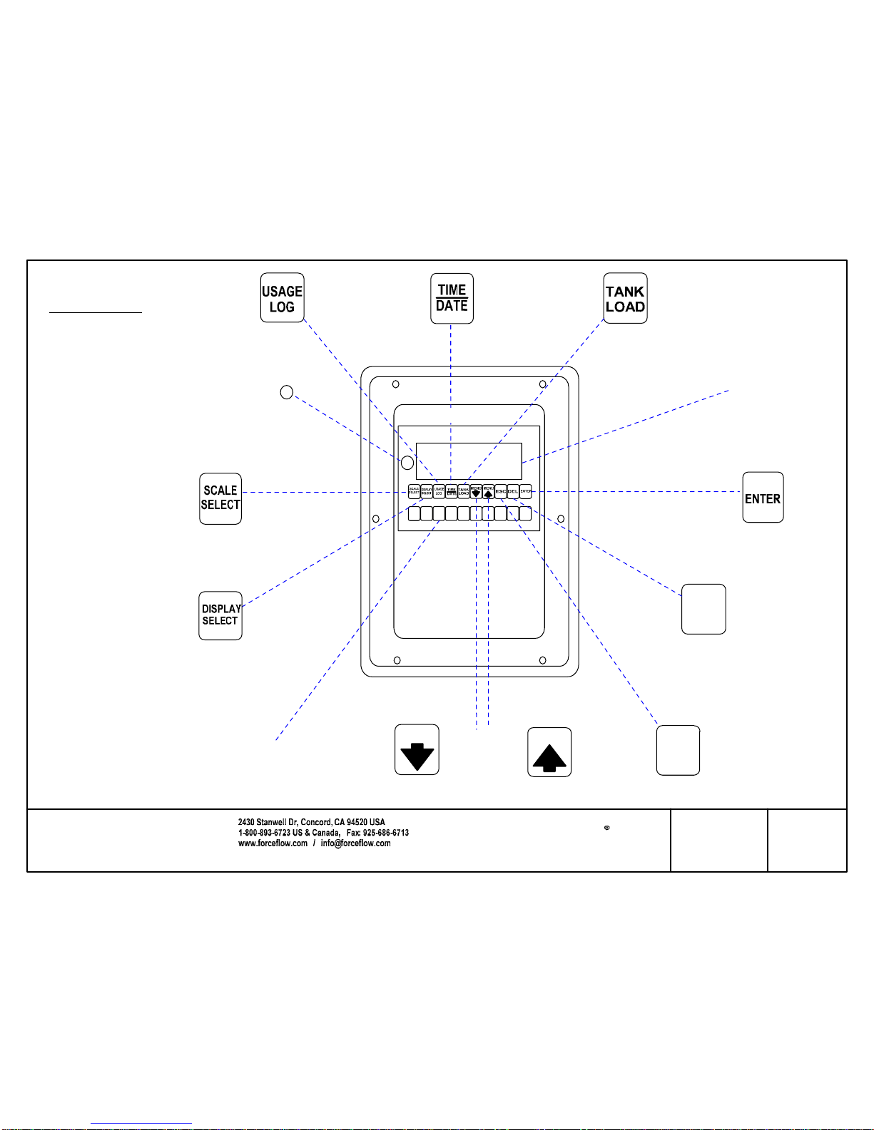
Scrolls forward through individual scales.SCALE SELECT
Toggles through a multi-function display for each scale in the
following decending order:
DISPLAY SELECT
1 NET REMAINING............
2 BAR GRAPH ..................
3 AVERAGE FEED RATE.
4 DAILY USAGE................
5 DAYS UNTIL EMPTY.....
6 AMOUNT USED ............
7 PERCENT FULL ............
8 BASE UNITS .................
Chemical remaining in tank or cylinder (default screen)
Analog bar graph. 0-100%
Chemical feed rate displayed as weight/volume per hour or day.
Amount of chemical fed so far today.
Days until empty at the current feed rate
A running total of net chemical used since last reset.
Numeric display of 0-100%.
Units of measure that Wizard was calibrated in.
Daily usages of most recent 31 days.
USAGE LOG:
Time and Date
TIME DATE
Loading new tanks or chemicals and entering tank tare weights.
TANK LOAD
ESCAPE key returns you to main display
ESC
These are the functions that are used on a day-to-day basis.
Access to USER and SETUP Menus. Allows
you to scroll through each of these Menus from
beginning to end.
MENU UP/DOWN
DELETE key backspaces or previous screen.
DEL
Data Entry or Advance to Next Screen.
ENTER

2430 Stanwell Dr, Concord, CA 94520 USA
1-800-893-6723 US & Canada, Fax: 925-686-6713
www.forceflow.com / info@forceflow.com
Drawn by: SLJ/MT
Date: 09/01/95
Revised: 04/08/08 MT
Scale: NONE
Drawing Number
File: T4\O&M\_NEW O&M 2007\W5 WIZ NEW PR328 WIZARD.tcw
CHANNELS:
INPUTS:
INCREMENTS:
DISPLAY UNITS:
RANGE:
RESOLUTION:
DISPLAY:
KEYBOARD:
OPERATING TEMP:
POWER:
CONNECTORS:
ENCLOSURE:
PERFORMANCE:
4-20mA OUTPUT SIGNALS (Model WMA420):
Up to 8 separate output signals (NET, RATE, DAILY, BULK or TOTALS)
1000 ohms max per output.
RELAYS (Models W5ASP-OD, W5AP-CD, W5ASP-OS & W5ASP-CS):
A maximum of 12 solid state or dry contact relays, NO/NC
latching/non-latching.
COMMUNICATIONS (Models WRS232 & WRS485):
RS232 Serial Port or RS485 Serial Network Port (MODBUS ASCII protocol).
SPECIFICATIONS
OPTIONS:
WIZARD 4000
ELECTRONIC INDICATOR
4000-1 (1-Channel)
4000-2 (2-Channel)
4000-3 (3-Channel)
4000-4 (4-Channel)
W.5
OPTIONS:
Qty Model Description
SUBMITTAL DATA: Wizard 4000 Model No.___________________
No. of Channels _____________
INPUTS
No. of Sourcing 4-20mA Outputs ________________________
No. of Relays: ____________________
____________________
Other Options ______________________________________________________________
__________________________________________________________________________
Dry Contact / Solid State
N.O. / N.C.
1 to 4 independent channels
Up to 4 electronic load cells or 1 Ultrasonic sensor
per channel
1, 2, 5, 10, 20, 50
LB, KG, GAL, LITER, IN, CM
0.01 TO 2,000,000
UP TO 20,000
2 lines, 16 characters per line, alphanumeric LCD
display backlighting, 0.4" characters
10 function keys, 10 numeric keys with tactile feedback
32 to 122 degrees F (0-50 degrees C)
110, 220 or 240 VAC, 50/60 Hz, 1/4 AMP Max.
Power and input/output - 1/2" nylon conduit connectors
Load Cells - 1/2" nylon cord connectors
Nema 4X, UL listed structural foam molded enclosure
Overall System Accuracy: 0.1 to 0.25% F.S.
Non-Linearity: <0.03% F.S.
Hysteresis: <0.02% F.S.
Non-Repeatability: <0.01% F.S.
Thermal Stability: <0.002% degrees F, zero and span
MODELS:
JOB REFERENCE: _______________________________________/s/___________
Dry Contact / Solid State
N.O. / N.C.
#3 NET 57.11 GL
#3 BULK 0.0 GL
6 5/8" (168mm)
10 1/2"
(266mm)
13"
(330mm)
Centerline
Mounting Brackets (4)
3" (76mm)
6" (152mm)
8 1/2" (216mm)
3/8" (9mm)
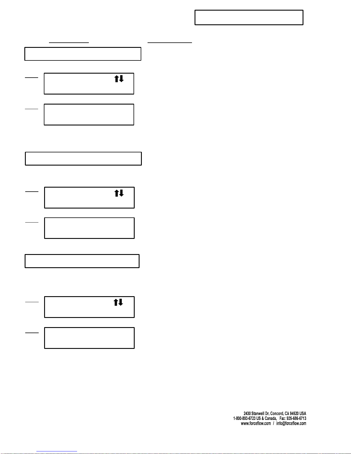
PRESS REPEATEDLY TO VIEW:
NET WEIGHT
FEED RATE
DAILY USAGE
DAYS UNTIL EMPTY
TOTAL USAGE
PERCENT FULL
BASE UNITS
BULK TANK SUPPLY
BAR GRAPH
PRESS BEFORE STARTING TANKCHANGES OR REFILLS TO
MAINTAIN ACCURATE USAGE DATA.
ACCESS "USER" AND "SETUP" MENUS. "USER" MENU LISTED
BELOW (SEE O&M MANUAL FOR "SETUP" MENU).
1 ALARM HISTORY
2 DATE LAST CLEARED
3 CLEAR AMOUNT USED
4 VIEW TOTAL
5 SET TIME & DATE
6 VIEW BULK SUPPLY
7 VIEW TARE
8 DISPLAY UNITS
9 SET ZERO
MOUNTING BRACKET (TYP 4 PLCS)
WIZARD 4000 +
0123456789
MENU
MENU
DEL
Toggles through a
multi-function display
for each scale.
Displays Daily Usage
for past 31 days
Toggles
Between
Individual
Scales
Return to Main
Default Screen
Backspace
or Back to Previous
Screen
Data Entry
and Advance
to Next Screen
Time and
Date
"NET WEIGHT"
"YES * NO"
ENTER SCALE #
Single or Dual
Display (16
Characters
per Line Screen)
Net Weight
Bar Graph
Feed Rate
Daly Use
Days Until Empty
Total Use
% Full
Base Units
Bulk
Scrolls Forward
and Backward
Through the Menu
Loading
New Tanks
or Chemicals
Numeric
Data Entry
Key Pad
Drawn by: SLP/MN
Date: 11/03/05 MN
Revised:
Scale: NONE
Drawing Number
File: T4\NEW O&M 2007\W6 WIZ NEW PRO328 BUTTONS.tcw
03/21/08 MT
30831
WIZARD 4000
KEYPAD FUNCTIONS
W.6
#3 NET 57.11 GL
Checked by: MN
ESC
#3 BULK 0.0 GL
*TO USE RESET BUTTON
*Reset Button &
Displays Software
Version
1. Push and hold "DEL" key.
2. While holding "DEL" key, push
and hold "RESET" button for 2
seconds.
3. After 2 seconds release ONLY the
"RESET" button, but continue to hold
down the "DEL" key until the display
reads one of the following:
Release "DEL" key.
Press "MENU" arrow keys to choose "NO"
Press "MENU" arrow keys to choose different
number than you did before.

WARNING ! DO NOT UNLOAD or LOAD tanks until "CHANGE TANKS NOW, THEN
PRESS ENTER" appears on the display. If you load or unload tanks
before reaching this step, the "AMOUNT USED" and "DAILY USAGE"
displays will be incorrect.
It also allows you to enter the tare weight(s) of your tanks if you choose "Manual" tank load mode, or load the
net weight of a cylinder if you chose the "Auto" tank load mode.
'TANK LOAD" key allows you to load new tanks without adversly
affecting the "AMOUNT USED" and "DAILY USAGE" displays.
Press "TANK LOAD" key to enter the tank load mode.
Remove empty tanks and place new tank(s) onto the scale
then press "ENTER" key to continue.
#2 TANK #1 TARE
#1 NET = 0 LB
#2 NET = 1950 LB
ARE YOU SURE
....If you chose "AUTO" the WIZARD automatically loads the
net weight and goes into the weighing mode (skip Step 6).
CHANGE TANKS NOW
THEN PRESS ENTER
WAIT
TANK TARE
*AUTO MANUAL
Verify you would like to continue tank load procedure.
Press "MENU" arrow keys to select which method, then press "ENTER".
MANUAL Mode: Requires that you enter tare weight of EACH tank on
EACH scale. (Example: Scale #2, tare weight of TANK #1is 1234 lbs.,
then TANK #2, etc). After entering the tare weights of all your tanks, the
WIZARD 4000 automatically adds them up and subtracts them from
the gross weight.
Step 6
Digital Display Action Required - Press "ENTER" after completing each step.
Step 2
Step 4
Step 5
Step 3
Step 1
....If you chose "MANUAL" you will manually enter tank
tare weight in Step 6.
....If MANUAL chosen above in Step 3...
Use "MANUAL" for PARTIALLY FULL containers.
Use "AUTO" for FULL containers.
TANK LOAD MODE
Fill your tank with chemicals, then press "ENTER" key to continue.
FILL TANK NOW
THEN PRESS ENTER
Step 7
"PORTABLE" Tank Applications (follow Steps 1 thru 6 only), such as
Ton Containers, Drums and Cylinders.
"PERMANENT" Tank Applications (follow Steps 1, 2 and 7 only), such as
Chem-Scale, Hoppers, Procells and Ultrasonic
Skip to STEP 7 in "PERMANENT" Tank Applications.
QUESTIONS ? Help Hotline: 1-800-893-6723 W.7
File: T4\NEW O&M 2007\W7 WIZ NEW DAY1C.tcw
NO *YES
LBS = 1234
SELECT CHANNEL Use "MENU" arrow keys, to choose channel, press "ENTER"
to accept the channel you want to load/unload tanks. This
"freezes" or "holds" the AMOUNT USED and DAILY USAGE
displays until tank load procedure finishes.
Step 2 , enter CH# 1
WIZARD 4000 TANK LOAD PROCEDURE:

2430 Stanwell Dr, Concord, CA 94520 USA
1-800-893-6723 US & Canada, Fax: 925-686-6713
Drawing Number
File: T4\NEW O&M 2007\W8 WIZ NEW INTRINSIC WIZ SOLO.tcw 30774
HAZARDOUS LOCATIONS
NON-HAZARDOUS LOCATION
CONDUIT MUST BE
SEALED PER
ELECTRICAL CODE
ELECTRONIC
LOAD CELL
WALL
LOAD CELL
CABLE
Allows refilling of tanks. To maintain accur ate usage data,
DO NOT fill tanks unt il STEP 3.
PressTANK LOAD button
Press 1 2 3 or 4 to select which scale,then press ENTER .
Fillyour tanksnow ! Then press ENTER
Togglesthroughdisplay options:
NetRemaining,AmountUsed,Average
Feed Rate , DaysUn til Empty, Daily Usage
Togglesthroughdisplay forthe totals
ofall scales
1
2
3
SAFETY BARRIER
(IF REQUIRED)
FOR HAZARDOUS LOCATIONS, VERIFY ELECTRONIC LOAD CELL(S)
FURNISHED WITH YOUR SCALE HAVE THE FOLLOWING LABEL TO
MEET SAFETY REQUIREMENTS:
FOR FURTHER TECHNICAL INFORMATION OR FOR APPLICATIONS
ENGINEERING ASSISTANCE, PLEASE CONTACT FORCE FLOW
1-800-893-6723.
HAZARDOUS LOCATION
INDICATOR IS NOT APPROVED FOR USE IN HAZARDOUS LOCATIONS.
IF YOUR INSTALLATION CONSTITUTES AN EXPLOSIVE OR COMBUSTIBLE
ENVIRONMENT, PLEASE CONSULT FACTORY FOR SAFETY PRECAUTIONS.
W.8
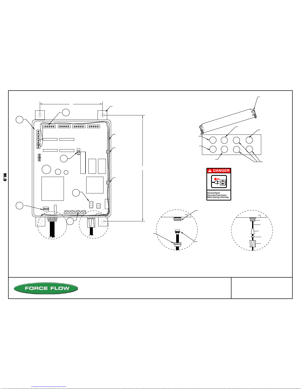
4-20mA
CONNECTIONS
LOAD CELL/ULTRASONIC CONNECTIONS
#1 #2 #3 #4
DISPLAY ANGLE
ADJUSTMENT (BLUE)
EPROM
RAM
CPU
POWER SUPPLY
POWER IN
CONNECTOR SLEEVE
PLASTIC WASHER
RUBBER GROMMET
CABLE
CONDUIT FITTING
BOX
#1#2#3#4
BOX (FRONT VIEW)
1/4" CORD CONNECTOR, USED FOR:
32
4
1
6 SLOTTED PAN
HEAD SCREWS.
(TIGHTEN SCREWS
EVENLY TO
GET UNIFORM SEAL
ON COVER GASKET)
3RD: ATTACH TO CONDUIT
OR CABLE CONNECTOR
FITTING ON BOX
2ND: SCREW CONDUIT
CONNECTOR ONTO
CONDUIT
1ST: SLIP CONDUIT
FITTING BASE
OVER CONDUIT
1/2" CONDUIT CONNECTOR, USED FOR:
5
LOAD CELL CABLE
ULTRASONIC CABLE
POWER
4-20 MA SIGNAL
RELAY WIRING
COMMUNICATIONS
6
NOTE:
Mount Indicator at "EYE LEVEL"
for easy viewing.
FUSE
BOX (BOTTOM VIEW)
1
3
42
2430 Stanwell Dr, Concord, CA 94520 USA
1-800-893-6723 US & Canada, Fax: 925-686-6713
Drawn by: SLP/MD
Date: 09/01/95
Revised: 12/05/06 PR328
Scale: NONE
DrawingNumber
File: T4\NEW O&M 2007\W9 WIZ NEW PR328 INDI.tcw 29893
WIZARD 4000 INDICATOR
WIRING REFERENCE
4-20mA WIRING,
LOAD CELL CABLE,
ULTRASONIC CABLE
WIRE/CABLE
CLAMP
CORD
CONNECTION
CONDUIT
CONNECTION
LOAD CELL/ULTRASONIC
SENSOR (1/4" CORD
CONNECTION)
4-20mA OUTPUT
(1/2" CONDUIT
CONNECTION)
RS485/RS232
(1/2" CONDUIT
CONNECTION)
110V/240V POWER CONNECTION
(1/2" CONDUIT CONNECTION)
RELAYS (1/2" CONDUIT CONNECTION) OPTIONAL LOAD
CELL or ULTRASONIC
(1/4" CORD
CONNECTION)
BOX
CONDUIT
CONNECTION CORD
CONNECTION
P1
+24VDCfor
Ultrasonics
RELAYS
#1
#2
#3
#4
+
_
T
G
R
RS485
RS232
WIRE/CABLE
CLAMP
6'
13"
MOUNTING
FIXTURE
®

EPROM
RAM
CPU
POWER
SUPPLY
POWER IN
Scale#1
HI
LO
Scale#1#2#3#4
11 12 13 14
SH
-X1
+X1
+S1
-S1
+X2
+S2
-S2
-X2
SH
+X3
+S3
-S3
-X3
SH
+X4
+S4
-S4
-X4
SH
NOTE:Forbestviewing,mountindicatorat"eyelevel".
LOAD CELLS
or
ULTRASONIC
SENSORS
FUSE
RELAYS
#1
#2
#3
#4
6"
13"
WIRE CABLE CLAMP
DISPLAY ANGLE
ADJUSTMENT (Blue)
MOUNTING
FIXTURE
4-20mA OUTPUT
Drawing Number
File: T4\NEW O&M 2007\W10 WIZ NEW PR328 INDIA.tcw
29892
WIZARD 4000 INDICATOR
COMPONENT LAYOUT
Scale#2
Scale#3
Scale#4
W.10
P1
+24VDCfor
Ultrasonics
RS232 (J1)
+
_
R
G
T
RS485
RS232
RS485 (J4)
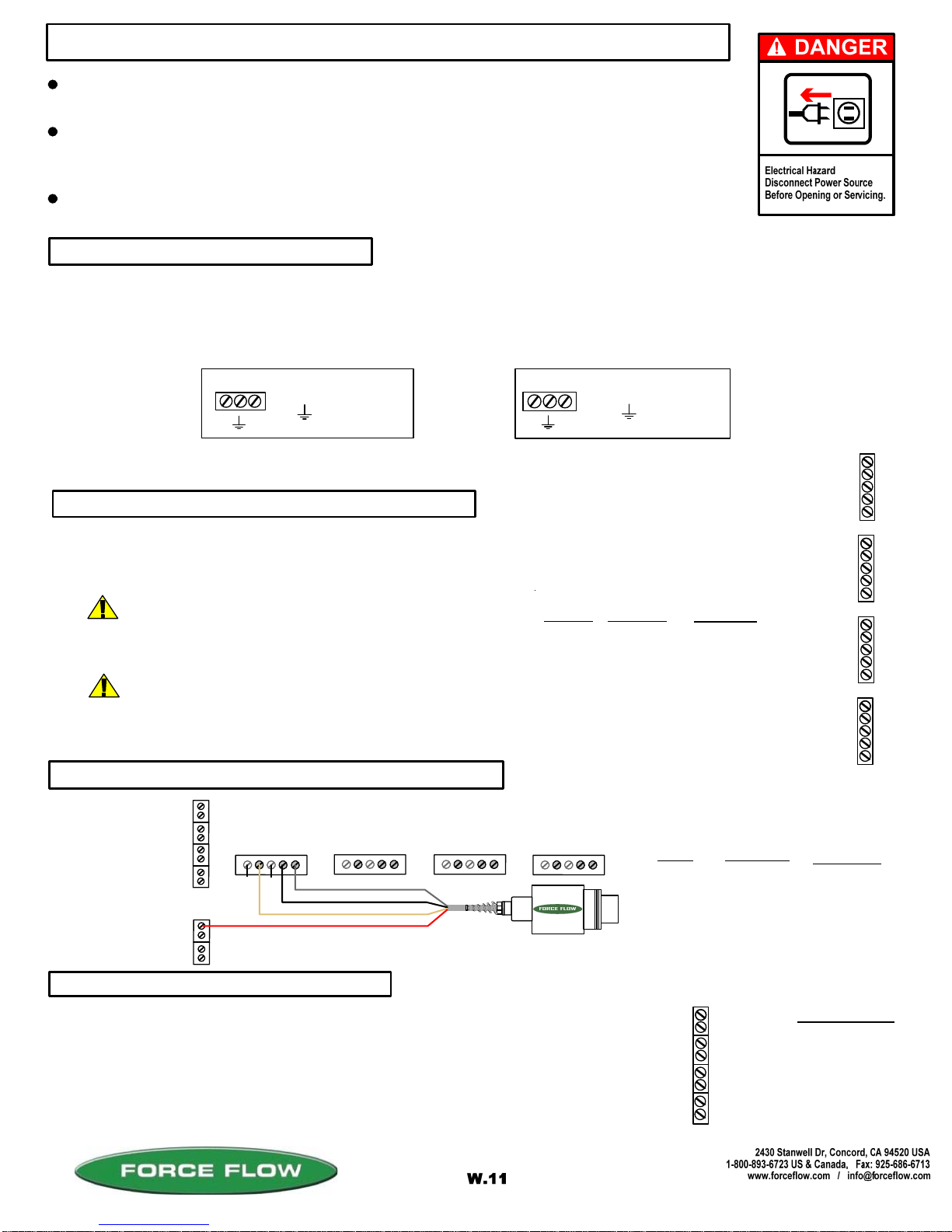
TURN OFF MAIN POWER BEFORE CONNECTING !! Use a dedicated 110/220 VAC (using 220 VAC requires
changing the voltage selector switch position to 220 VAC. This switch is located between the incoming power
connector and the power transformer) power line, connected directly to the main power panel at the facility. DO NOT
connect any other inductive loads, relays, etc. to this power line ! Resulting power surges can damage the
electronics !!! Use far left bottom port and connect per following: (NOTE: Use 1/2" conduit connector)
QUESTIONS ? Help Hotline: 1-800-893-6723
Your 4-20 MA signals are internally powered for up to 900 OHMS each.
DO NOT use external loop power. Run 4-20 MA wiring up the right hand
side of enclosure using the cableclamps to keep wires off of PC Board.
(NOTE: Use 1/2" conduit connector). If more than one (1) 4-20 MA
signal is used, you may use the same conduit and connector, but DO NOT
run 4-20 MA signals with any other power lines, which carry an inductive load.
+ 4-20MA LOOP
- 4-20MA LOOP
DESCRIPTION
POWER IN (110 VAC)
The Wizard 4000 indicator is shipped with the load cell(s) already connected. If routing load cell cable through conduit
or trimming cable length, remove cable connector from motherboard, then cable from connector and finally cable from
Wizard enclosure. After routing cable through conduit or trimming length, reverse above procedure to reconnect. A
separate cord connector is provided into the enclosure for each load cell cable.
+ EXCITATION
+ SIGNAL
- SIGNAL
- EXCITATION
SHIELD
WIRE COLOR
RED
GREEN
WHITE
BLACK
BRAIDED WIRE
PC BOARD
+ X
+ S
- S
- X
SH
+X4
+S4
-S4
-X4
SH
+X3
+S3
-S3
-X3
SH
+X2
+S2
-S2
-X2
SH
+X1
+S1
-S1
-X1
SH
Scale#4
Scale#1
Scale#2
Scale#3
DESCRIPTION
-
+
-
+
-
+
-
+
14
13
12
11
Scale #4
= HOT
= GROUND
= COMMON
3 4-20 MA SIGNALS
2 IF "LOAD CELL" CONNECTION
1 POWER HOOK-UP
+ C
File: T4\NEW O&M 2007\W11 WIZ NEW PR328 WZININST.tcw
04/08/08 MT
Scale #3
Scale #2
Scale #1
+ C
+
C
WIZARD 4000 INDICATOR INSTALLATION & WIRING
ALL CONNECTORS HAVE A "PLUG-IN" FEATURE TO ASSIST IN CONNECTING WIRES.
REMOVE THE CONNECTOR FROM THE BOARD BEFORE ATTACHING WIRES.
ALWAYS SHUT OFF MAIN POWER, AS WELL AS POWER TO ANY AUXILIARY EQUIPMENT
THAT WILL BE INSTALLED IN THIS UNIT, BEFORE OPENING FRONT OF CASE !!
INDICATOR IS NOT APPROVED FOR USE IN HAZARDOUS LOCATIONS. IF YOUR INSTALLATION
CONSTITUTES AN EXPLOSIVE OR COMBUSTIBLE ENVIRONMENT, PLEASE CONSULT FACTORY
FOR SAFETY PRECAUTIONS.
2 IF "ULTRASONIC SENSOR" CONNECTION
P1
+X1
+S1
-S1
-X1
SH
+X2
+S2
-S2
-X2
SH
+X3
+S3
-S3
-X3
SH
+X4
+S4
-S4
-X4
SH
Scale #1 #2 #3 #4
RED (+ EXCITATION) to -V
WHITE or CLEAR to +MA
B LACK (GROUND) to - MA
SILVER or BARE (SHEID) to GRD
BOARD
P1
+SI
- X1
SH
WIRE COLOR
RED
WHITE
BLACK
SILVER
DESCRIPTION
+ EXCITATION
+ SIGNAL
GROUND
SHIELD
UNUSED
UNUSED
14
13
12
11
= HOT
= GROUND
= HOT
+
C
POWER IN (220 VAC)
OR
CHOOSE THE 2ND STEP THAT RELATES TO THE EQUIPMENT PURCHASED:
®
ROUTING CABLE IN CONDUIT
TRIMMING LOAD CELL CABLE
More than one load cell can be routed in a single
conduit. Load cells must not share conduit with
power lines or wiring from any inductive load.
Wizard 4000 is pre-calibrated at factory based on supplied cable lengths. Depending
on how much cable is trimmed, field recalibration of Wizard may be required for best
accuracy. Contact factory for more information.
(OPTION MODEL NO. WMA420)

CAUTION should be observed whenever box is open to avoid damage or memory loss by static
electricity. DO NOT touch any of the circuit board, other than the intended contact noted in these
instructions. Carpets especially can build up static electricity.
The Wizard display has been factory adjusted for standard "eye level" viewing.
If you install your indicator at a height other than eye level, you may adjust the
display angle for best viewing. Turn the blue screw potentiometer (R9 located
near the middle of the motherboard) clockwise or counter clockwise until display
appears correct at your viewing angle. The potentiometer is a 30 turn, no stop
design. A slight click will be heard when you reach min. or max. adjustment.
Be sure that indicator power circuit is sufficiently protected against transient lightning strikes
and power surges. Improper protection may void your warranty.
STATIC ELECTRICITY PROTECTION
LIGHTNING ~ SURGE PROTECTION:
6 DISPLAY VIEW ANGLE ADJUSTMENTS
5 RELAY OPTION
4 MODBUS SERIAL COMMUNICATION OPTION
QUESTIONS ? Help Hotline: 1-800-893-6723
W.12
File: T4\NEW O&M 2007\W12 WIZ NEW PR328 WZININ2A.tcw
05/23/08 MT
NO: Circuit IS complete until relay is activated. (i.e. turning OFF a pump)
RELAYS
NC: Circuit is NOT complete until the relay is activated. (i.e.turning ON a warning light).
#1
OUT(1)
IN(1)
OUT(2)
IN(2)
OUT(3)
IN(3)
OUT(4)
IN(4)
SOLID STATE relays for external apparatus (pumps, valves,
alarms, etc) may be ordered either Normally Open (NO) or
Normally Closed (NC).
SOLID STATE relays are rated at: 3amp Max. (fused @ 4amp) 1.5amp motorload.
The Wizard 4000 is provided with a separate 1/2" conduit connector for your relay wiring.
To format relays, go to SETUP MENU 12, "ALARM/RLY CONFIG".
DRY CONTACT relays (SCADA, PLC, etc) inputs may be ordered either Normally Open
(NO) or Normally Closed (NC).
DRY CONTACT relays are rated at: 0.5amp @ 12VDC maximum (fused @ 1amp).
#2
#3
#4
The Wizard 4000 is provided with a separate 1/2" conduit connector for your serial port
communication wiring. DO NOT co-locate inductive load wiring or power lines with
communication wiring. Attach your communication wiring per the following:
RS232 RS485
Data OUT line
+
_
R
G
T
RS485
J1
Data IN line
Signal Ground Positive
Negaitive
R9
Potentiometer (blue)
located near middle
of motherboard
FOR RS485 SHIFT JUMPER
TO RIGHT 2 PINS
FOR RS232
SHIFT JUMPER
TO LEFT 2 PINS
(OPTION MODEL NO's: W5ASP-OD, CD, OS, CS)
(OPTION MODEL NO's: WRS232 & WRS485)
J4
RS232
This function allows the user to find out the last time and date the
"Amount Used" display was cleared or reset for each scale.
Press "ENTER" key to continue.
ACTION REQUIRED:
DIGITAL DISPLAY:
2 DATE LAST CLEARED
1 ALARM HISTORY
USER MENU (WIZARD 4000)
QUESTIONS ? Help Hotline: 1-800-893-6723
W.13
File: T4\NEW O&M 2007\W13 WIZ NEW WZPR328 DAY1.tcw
03/21/08 MT
MENUS
USER SETUP
USER MENU
ALARM HISTORY 1
ALARM HISTORY
3 BL 9/25 9:10
USER MENU
DATE LAST CLRD 2
Step 1
Step 1
Step 2
CH# 1 CLEARED
Step 2
8/19/ 5 14:15
Displays DATE and TIME the "AMOUNT USED" function was
last cleared (for approximately 1 minute). Use the "MENU"
arrow keys to toggle through other channels. Example: Channel 1
was last cleared on 8/19/05 at 14:15 hours (2:15 pm).
3 CLEAR AMOUNT USED
USER MENU
CLR AMOUNT USED 3
Step 1
CLEAR ALL CHAN ?
Step 2
Clears or resets the "AMOUNT USED" and 'DAILY USAGE"
displays to zero.
SELECT CHANNEL
Step 3
NO YES
ARE YOU SURE
Step 4
, enter CH# 1
Press "ENTER" key to continue.
Use 'MENU" arrow keys to choose "NO" or "YES".
Press "ENTER" key to accept. Choosing NO takes
you to Step 3 to choose which channels. Choosing
YES asks "ARE YOU SURE?" and clears ALL channels
NO YES
Use 'MENU" arrow keys to choose which channel to clear.
Press "ENTER" key to accept.
Use 'MENU" arrow keys to choose "NO" or "YES".
Press "ENTER" key to accept.
A
llows the user to retrieve the time, date, and type of alarm for
the most recent 10 alarm conditions.
3 = Channel
You may scroll through these items with the "MENU" arrow keys, or simply
enter the Menu Item Number to jump straight to that menu item.
MENU Arrow Keys: There are 2 menus that may be accessed via the "MENU" keys. The "USER" Menu
and "SETUP" Menu. The "USER" Menu has 8 menu items, and these are functions that are used for
day-to-day operations. The "SETUP" Menu has 17 menu items, and these are functions that are used
during equipment start-up, or if your chemical feed operation has been changed.
ALARM CODE ABREVIATIONS: 3 B L
A = Setpoint A
B = Setpoint B
R = Feedrate
D = Daily
LC = Load Cell Failure
BK = Low Bulk Supply
SF = Slow Fill
H = High
L = Low
Press "ENTER" key to continue.
Channel 3 had a SETPOINT B LOW LEVEL condition
on 9/25 at 09:10 hours (9:10 am). Press "ENTER" key
to continue. "DEL" key to return to "USER" menu.

Sets time and date.
Press "ENTER" key to continue.
ACTION REQUIRED:
DIGITAL DISPLAY:
5 SET TIME & DATE
USER MENU continued...
QUESTIONS ? Help Hotline: 1-800-893-6723 W.14 File: T4\NEW O&M 2007\W14 WIZ NEW PR328 DAY2.tcw
03/21/08 MT
USER MENU
VIEW TOTAL 4
CHAN 1, 2
tNET 26.0 LB
USER MENU
SET TIME & DATE 5
Step 1
Step 1
Step 2
6 SET BULK SUPPLY
This display shows that the total Net weight of channels 1 and 2
is 26.0 lbs. Press enter again for total feed rate of channels 1 &
2, and again for total usage on channels 1 & 2.
SET TIME & DATE
Step 2
Example: YEAR 2005 = "5", YEAR 2010 = "10"
Press "ENTER" key after each enter to get
MONTH, DAY, HOUR and MINUTES.
Note: Use Military time for HOURS (1 to 24).
YEAR=
MONTH=
DAY=
HOURS=
MINUTES=
5
9
27
14
15
Press "ENTER" key to continue.
USER MENU
SET BULK SUPPLY 6
Step 1
A
llows user to view the remaining inventory in their bulk supply
tank even though they have no level sensor hooked up to the
bulk tank. Before filling your day tank, press the “TANK LOAD”
key & follow the menu prompts. The Wizard will then subtract
how much is added to the day tank from the remaining bulk
supply number. This function must be turned on under the
BULK SUPPLY selection in the SET UP MENU. Press “ENTER”
key to continue.
#2 BULK SUPPLY
LBS = 2900
Step 2 This display shows that Channel #2 has a bulk supply tank that
contains 2900 lbs of chemical
7 VIEW TARE
USER MENU
VIEW TARE 7
Step 1
#3 VIEW TARE
LBS = 25.0
Step 2
Press "ENTER" key to continue.
Tare weight will be displayed. Example: Channel #3
tare weight is 25.0 lbs.
A
llows users to view the tare weight of their tank. This function
is only active when the system is configured for “portable
tanks” like chlorine, drum, carboy and tote scales.
4 VIEW TOTAL
A
llows user to view the combined Net, Rate and Usage for more
than 1 channel. This function must be configured under the
SETUP VIEW TOTAL selection in the SET UP MENU. Allows you
to choose which channels to total.
Press "ENTER" key to continue.
tNET = Net Weight
tRATE = Feed Rate
tUSED = Total Usage

ACTION REQUIRED:
DIGITAL DISPLAY:
USER MENU continued...
QUESTIONS ? Help Hotline: 1-800-893-6723
W.15
File: T4\NEW O&M 2007\W15 WIZ NEW PR328 DAY3.tcw
03/21/08 MT
USER MENU
SET ZERO 9
SET ZERO
NO YES
Step 1
Step 2
8 SET ZERO
SELECT CHANEL
, enter CH# 1
Step 3
Allows user to "zero" the scale or sensor when tank or
scale is empty. If tank is not empty but weight of chemical
in tank is known, SET ZERO allows user to adjust display
to read this known weight.
Press "ENTER" key to continue.
Select channel (scale or sensor number) using arrow keys,
then press ENTER.
NOTE:
If system was not initially zeroed BEFORE chemical was added to tank, the NET WT
may not accurately reflect the actual amount in tank.
To adjust without emptying tank, use the zero function located in SETUP MENU 15,
"FIELD CAL". That zero function prompts for MINIMUM AMOUNT (amount of chemical
currently in tank).
ARE YOU SURE
Step 3
NO YES
Use MENU keys (UP/DOWN ARROWS) to select NO or YES,
then press ENTER.
Use MENU keys (UP/DOWN ARROWS) to select NO or YES,
then press ENTER.

Press "ENTER" key to continue.
ACTION REQUIRED:
DIGITAL DISPLAY:
1 DISPLAY FORMAT
QUESTIONS ? Help Hotline: 1-800-893-6723
W.16 File: T4\NEW O&M 2007\W16 WIZ NEW PR328 SETUP1.tcw
03/21/08 MT
SETUP MENU
DISPL FORMAT
1
SELECT FORMAT
SINGL DUAL
Step 1
Step 2
2 CHANNEL ID
SETUP MENU
# CHANNEL ID # 2
Step 1
#1 CHANNEL ID#
Step 2
Press "ENTER" key to continue.
NUMBER = 1
AUTO SCAN ?
NO YES
Step 3
ALTERNATING TIME
SECONDS = 6
Step 4
Configures how many channels are displayed simultaneously,
and whether the auto scan is engaged.
Choose a single channel to be displayed, or 2 channels to be
displayed if a multichannel indicator is being used.
Use “MENU” arrow keys to select. If “YES” is selected, the
Wizard will automatically scan all the channels in the Wizard
without the operator having to touch any keys. Display Format
menu is exited if “NO” is selected.
A
llows you to set the scan time period in seconds from one
channel to the next.
If there are multiple Wizard controllers on a single site, this
function allows you to assign an Identification Number from 1-
99 for each channel.
Use the numeric keypad to enter any number from 1 to 99.
3 100 PERCENT
SETUP MENU
100 PERCENT 3
Step 1
#1 100 PERCENT
Step 2
Press "ENTER" key to continue.
GAL = 400.00
A
llows you to tell the Wizard what value you consider 100% full.
This will calibrate the BAR GRAPH and PERCENT function for
the “Display Select” key.
Enter value that you consider 100% full.
MENUS
USER SETUP
You may scroll through these items with the "MENU" arrow keys, or simply
enter the Menu Item Number to jump straight to that menu item.
SYSTEM ADDRESS
Step 3
NUMBER = XXX
Set MODBUS device address (1 to 247)
*Only visible if OPTIONAL MODBUS Serial Communication enabled.
MENU Arrow Keys: There are 2 menus that may be accessed via the "MENU" keys. The
"USER" Menu and the "SETUP" Menu. The "USER" Menu has 8 menu items and these are
functions that are used for day-to-day operations
The "SETUP" Menu has 17 menu items, and these are
functions that are used during equipment startup,
or if your chemical feed operation has been changed.
Press "ENTER" key to continue.
ACTION REQUIRED:DIGITAL DISPLAY:
4 AUTO LOAD
SETUP MENU continued...
QUESTIONS ? Help Hotline: 1-800-893-6723
W.17
File: T4\NEW O&M 2007\W17 WIZ NEW PR328 SETUP2.tcw
SETUP MENU
AUTO LOAD 4
#1 TANK NET
LBS = 2000
Step 1
Step 2
6 MOTION BAND
SETUP MENU
MOTION BAND
6
Step 1
#2 MOTION BAND
Step 2
Press "ENTER" key to continue.
GAL = .02
For portable tank (load on/ load off) applications, this allows
you to set the net weight of the container so that when using
the “TANK LOAD” key, the Wizard will automatically load the
net weight of the containers that you are loading.
Enter the value of the net weight that your containers are
filled with: Examples
2000 lbs = Ton Containers USA
150 lbs = 150 lb cylinders USA
907 kgs = Canadian ton containers
1000 kgs= Metric ton containers
Press "ENTER" key to continue.
5 FILTER BAND
SETUP MENU
FILTER BAND
5
#1 FILTER BAND
GAL = 0.70
Step 1
Step 2
A
llows you to steady a fluctuating display. This function will only help
smooth out fairly rapid fluctuations. Slow, long term fluctuations (over
minutes or hours) will likely not be corrected by changing the filter
value. Contact factory for assistance in correcting slow, long term
display fluctuations.
Menu operations such as TANK LOAD, ZERO and FIELD
CALIBRATION require the Wizard in certain steps to store a weight
value before moving to the next step. MOTION BAND determines how
steady the weight reading is required to be before the Wizard accepts
the value and continues on. The greater the value, the greater the
fluctuation allowed.
Changing this value will rarely be required. If a menu operation will not
advance from the “Wait …” screen, you may ESC from the operation
then increase this value and try the function again. The “WAIT . . .”
screen indicates the Wizard is waiting for the weight to stabilize
(sloshing chemical in tank) to a value within the MOTION BAND value.
This value can be set to any number greater than 0.

ACTION REQUIRED:DIGITAL DISPLAY:
SETUP MENU continued...
QUESTIONS ? Help Hotline: 1-800-893-6723
W.18
File: T4\NEW O&M 2007\W18 WIZ NEW PR328 SETUP3.tcw
PERIOD BASE
MIN HOUR
Step 3
Step 4
Use "MENU" arrow keys to choose MINUTES or HOURS.
Press "ENTER" key to accept.
UPDATE PERIOD
MINUTES = 1
Step 5 SHIFT START HOUR
0 - 23 0
Step 6 #2 PAUSE/PROJ
NO YES
Use the “MENU” arrow key to choose NO or YES. Choosing
YES turns on the “PAUSE & PROJECT” feature which allows
the Wizard to keep track of chemical usage while your tank is
getting refilled. By pressing the “TANK LOAD” key before and
after your tank fill is done, the Wizard calculates how much
was used during the fill process based on total time and most
recent feed rate. The Wizard then adds this amount back to
your usage data.
Enter the hour at which you want the daily usage accumulator
to begin (in military time). “0” is midnight; 8 is 8am, 13 is 1pm,
etc.
Use "MENU" arrow keys to update increment. Press "ENTER"
key to accept.
MIN Choices: 1, 2, 5, 10, 20, 30, 60
HOUR Choices: 1, 2, 4, 6, 8, 12, 24
7 SYSTEM TIME BASE
SETUP MENU
SYSTEM TIME BASE
Step 1
Step 2
Press "ENTER" key to continue.
RATE TIME BASE
HOUR DAY
A
llows configuring of feed rate update periods, daily usage
update periods, and whether the pause and project function
is used.
Use "MENU" arrow keys to choose time base of
HOUR or DAY. Press "ENTER" key to continue.
7
Allows you to choose between "Lbs (or Gallons) per day" and "Lbs. (or gallons) per hour" and allows you
to set your sample time or "update period" for your feed rate function.
IMPORTANT NOTE FOR SETTING UP YOUR "UPDATE PERIOD":
In general, if your feed rates are fairly constant on a daily basis, the longer you set your update period for,
the more accurate your feed rate function will be. However, if your feed rate varies from hour to hour or
minute to mintue, choose a shorter update period to give you a more accurate feed rate at a point in time.
You may have to experiment with different update periods to get the desired result for your application.
For certain applications with very low feed rates (less than 2% of full scale capacity per day), low sample
times will not give you accurate readings.
Use a Longer
Update Period
HIGH FEED
CONSTANT
LOW FEED (less than 2% capacity/day)
N/A (Not Accurate)
Use a Short
Update Period
Use a Short or
Long Update Period
FLUCTUATING

ACTION REQUIRED:
DIGITAL DISPLAY:
SETUP MENU continued...
QUESTIONS ? Help Hotline: 1-800-893-6723 File: T4\NEW O&M 2007\W19 WIZ NEW PR328 SETUP4.tcw
04/08/08 MT
Step 2 #2 MONITOR BULK
NO YES
9 BULK SUPPLY
SETUP MENU
BULK SUPPLY
Step 1
Press "ENTER" key to continue.
9
# OF 4-20 PORTS
2 ACTIVE
Step 2
P1 USED FOR CH #
Step 3
, enter 1
PORT 1 CHAN 1
Step 4
, enter NET
PORT 1 RANGE FS
Step 5
GAL = XXXX.X
Momentarily displays number of active 4-20mA ports, then
automatically advances to Step 3.
Designate whether you would like NET, RATE, DAILY USAGE
or BULK data to be sent out on this port. Use the the “MENU”
arrow key to select then press “ENTER” key to continue
Use the numerical keypad to input what full scale output you
would like 20 mA to be equal to. 4 mA is always equal to 0.
Use "MENU" arrow keys to choose NO or YES, then press
"ENTER" key to continue.
SETUP MENU
CONFIG 4-20 OUT
Step 1
8 CONFIG 4-20mA OUT If you have 4-20 mA output hardware installed on your
motherboard, this allows you to configure your 4-20 outputs to
send either: NET; RATE; DAILY USAGE or BULK TANK data,
and set full scale value ( 20 mA = full scale).
Press "ENTER" key to continue.
8
FIXED TANK APPLICATIONS ONLY:
Step 2 #1 AUTO REFILL
LEVEL BATCH
10 AUTO REFILL
SETUP MENU
AUTO REFILL
Step 1 Press "ENTER" to continue to next screen.
10
Continued...
This option is used for stationary day tanks that refill their
Chemical from a bulk supply tank. By turning this function
on, it allows you to inferentially track remaining chemical in
the bulk supply tank.
This item is only available if you have purchased the
ARC4000 option.
LEVEL mode: Fills tank to preset level.
BATCH mode: Fills (adds) preset amount.
Designate which channel (1-4 or "TOTALS" you would like Port 1
(P1) output to be on. Use "MENU" arrow keys to select then press
"ENTER" key to continue. Repeat process for additional ports.
(OPTION MODEL NO. ARC4000)
Step 3 #1 AUTO REFILL
SEMI AUTO
SEMI requires operator to initiate fill using TANK LOAD key.
AUTO begins refill automatically.
(LEVEL MODE ONLY)
Other manuals for WIZARD 4000
2
Table of contents
Other Force Flow Accessories manuals


