FORCE Unlimited DUO-FORCE Operating and maintenance manual
DUO-FORCE
By FORCE Unlimited
FORCE Unlimited
1504 S. Frederick Avenue
Oelwein, IA 50662
(319) 283-4863
www.forceunltd.com
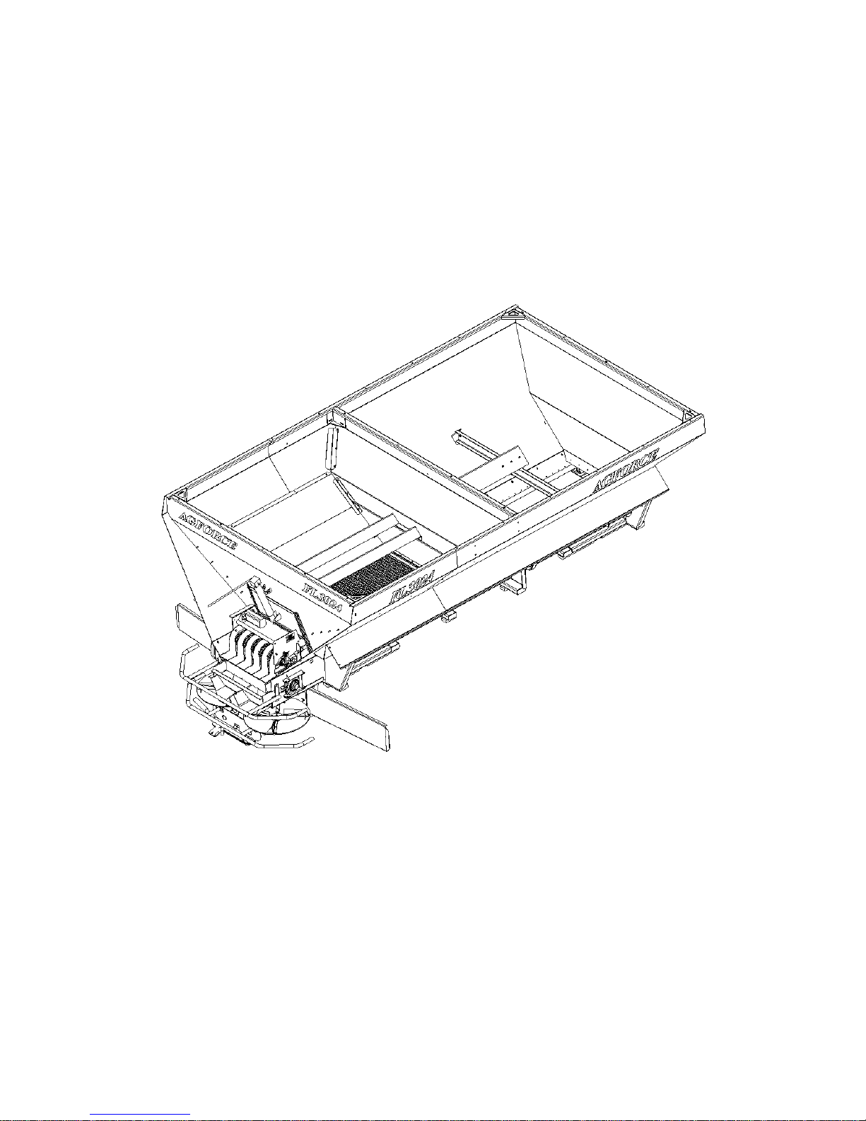
FOR AGFORCE FL3024

F
F
F
O
O
O
R
R
R
C
C
C
E
E
E
U
U
U
N
N
N
L
L
L
I
I
I
M
M
M
I
I
I
T
T
T
E
E
E
D
D
D
L
L
L
L
L
L
C
C
C
LIMITED WARRANTY
COMPANY NAME: _________________________________________________
COMPANYADDRESS: ______________________________________________
CITY: _______________________________ STATE: _______ ZIP: ___________
MODEL: ________________________________________
SERIAL NUMBER: _______________________________
DATE PURCHASED: _____________________________
DEALER NAME: ________________________________
DATE WARRANTY CARD RETURNED: _____________
VIA: _____ WEBSITE _____ MAIL

FORCE UNLIMITED LLC
LIMITED WARRANTY
FORCE Unlimited LLC has manufactured or is distributing the Product or Parts to which this warranty is attached.
It warrants that the Product or Parts will, under normal conditions of use and service, be free from material defects
due to faulty manufacturing for a period of twelve (12) months from the date of delivery to the original user. If any
Product or Part does not conform to this warranty, your Dealer will, at its option, repair or replace parts provided,
and you will pay all labor costs and costs for materials other than warranty parts. If Product or Part is defective in
materials or workmanship, you must promptly notify your Dealer and return to FORCE Unlimited or fax to 319-
283-3086 the warranty registration card within 30 days from the date of delivery to original user. The installation
of any Part that did not originate from FORCE Unlimited will void this limited warranty in its entirety. In the
event of repair or replacement, the warranty period shall not be extended beyond the original warranty period.
If you fail to return the warranty registration card (in parts manual) to FORCE Unlimited within thirty (30)
days after the date of delivery, this warranty shall not apply and your remedy for any defects in the Product
will be your responsibility.
The above warranty does not cover:
a. Product that is damaged by abuse, neglect, accident, or modification
b. Fluids, towing, telephone, travel, loss of vehicle, inconvenience
c. The product itself if parts are installed on the equipment that did not originate from FORCE Unlimited
The above warranty does not apply under the following conditions:
a. When Product has been improperly used or installed, modified, or fails because of defects or
inefficiency of components not furnished with the Product
b. When Product is used for purposes for which it was not originally designed or intended, or is used
under abnormal operating conditions
c. When the Dealer or end-user fails to follow FORCE Unlimited instructions regarding the Product
This warranty is extended only to the original user and is not transferable. In the event of a warranty claim,
you should promptly notify your Dealer and provide the following:
a. Model & serial number of the Product
b. Date of delivery to the original user
c. Part number of the defective Part
d. Description of the claim encountered
FORCE Unlimited LLC will bear no other expense including labor and material costs, other than those
specified above. Unless modified in writing and signed by both parties, this Limited Warranty is understood
to be the complete and exclusive agreement between the parties. No third party has authority to change or
modify this warranty in any aspect.

LIMITED WARRANTY
2 YRS
SHELL STRUCTURE, SPINNER FRAME (including inferior welds & cracking)
CONVEYOR GEARBOX (including gears, bearings & seals)
1 YR
SPINNER MOTORS & ADAPTERS (including bearings & seals)
CONVEYOR MOTORS (including bearings & seals)
VALVE MOTORS & CARTRIDGES
CONVEYOR CHAIN – BELT & FASTENERS
CONVEYOR SPROCKETS & BEARINGS
FAN & CONVEYOR RATE SENSORS
WEAR ITEMS
SPINNER FINS
SPINNER DISCS
MANUFACTURER HAS THE RIGHT TO REPLACE DEFECTIVE OR DAMAGED PARTS
WITH NEW OR REBUILT AT ITS OWN DISCRETION
PARTS DAMAGED FROM ABUSE OR IMPROPER MAINTENANCE NOT COVERED
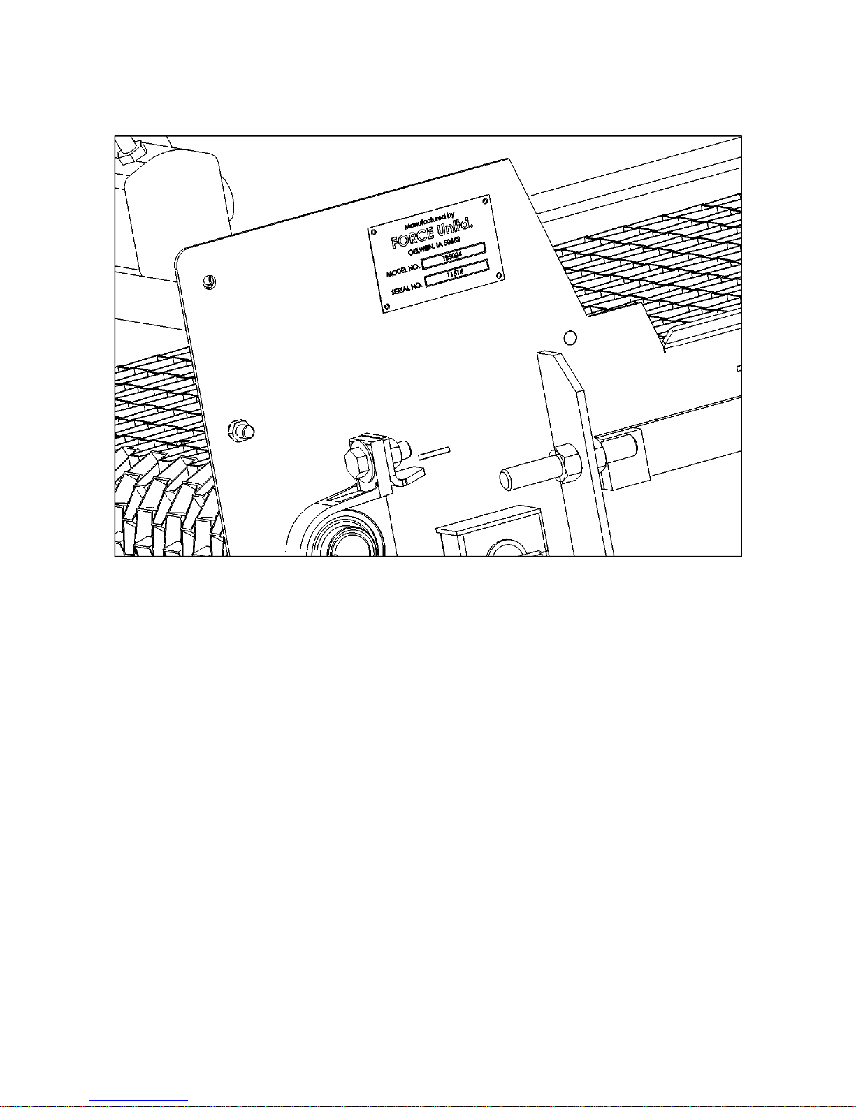
NOTE: THIS INSTRUCTIONAL MANUAL AND PARTS BOOK
ONLY APPLIES TO DUO-FORCE UNITS S/N 11514 AND AFTER.
IF YOUR UNIT USES RUBBER SEALING STRIPS INSTEAD OF
STAINLESS STEEL, OR HAS A SERIAL NUMBER PRECEDING
11514, CALL FORCE UNLTD. TOLL FREE AT 1-800-632-5986 FOR
DETAILS.

FORCE UNLTD. SPREADERS * GPS EQUIPMENT * CONVEYORS
HOME OF THE “FORCE”FIELD Table of Contents
Table of contents
item
Page no.
Instructional Manual
Initial Setup & Maintenance
1
Duo-Force Removal
2
Duo-Force Installation
4
Duo-Force Valve Block Visual Reference
9
Parts Manual
Hydraulic System
DF-1.1
Conveyor Drive
DF-2
Take-Up and Flow Reducer
DF-3
Panel Assembly
DF-4
Dual Inverted “V”
DF-5
Hillside Flow Divider
DF-6
FORCE UNLTD. SPREADERS * GPS EQUIPMENT * CONVEYORS
HOME OF THE “FORCE”FIELD Instructional Pg. 1
Duo-force
Initial setup & maintenance
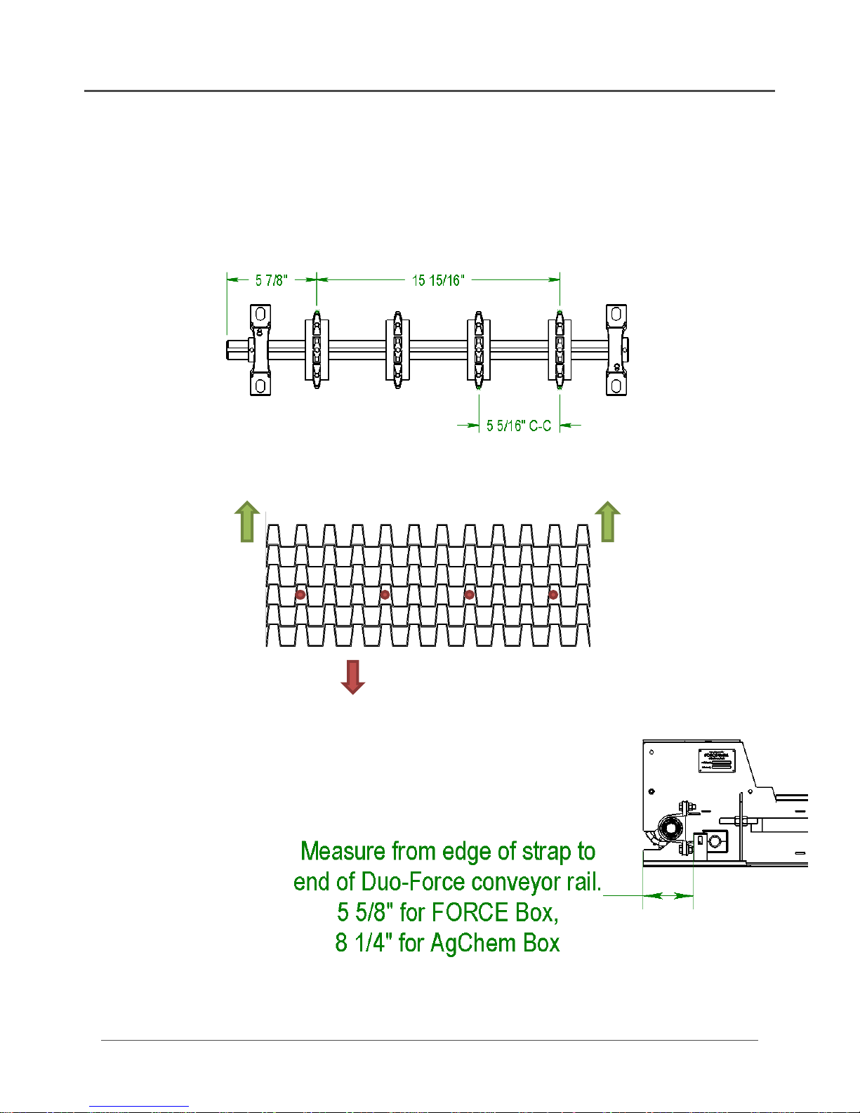
Sprocket Locations
FRONT OF BOX
BELT TRAVEL
NOTES:
1.) When flat wire belt is
properly tightened, you should
be able to lift the center of the
belt 1” – 1 ½” off the
conveyor bed.
2.) Check tension of 60 series
roller chain and flat wire
belting daily for first week of
operation and weekly
thereafter.
FORCE UNLTD. SPREADERS * GPS EQUIPMENT * CONVEYORS
HOME OF THE “FORCE”FIELD Instructional Pg. 2
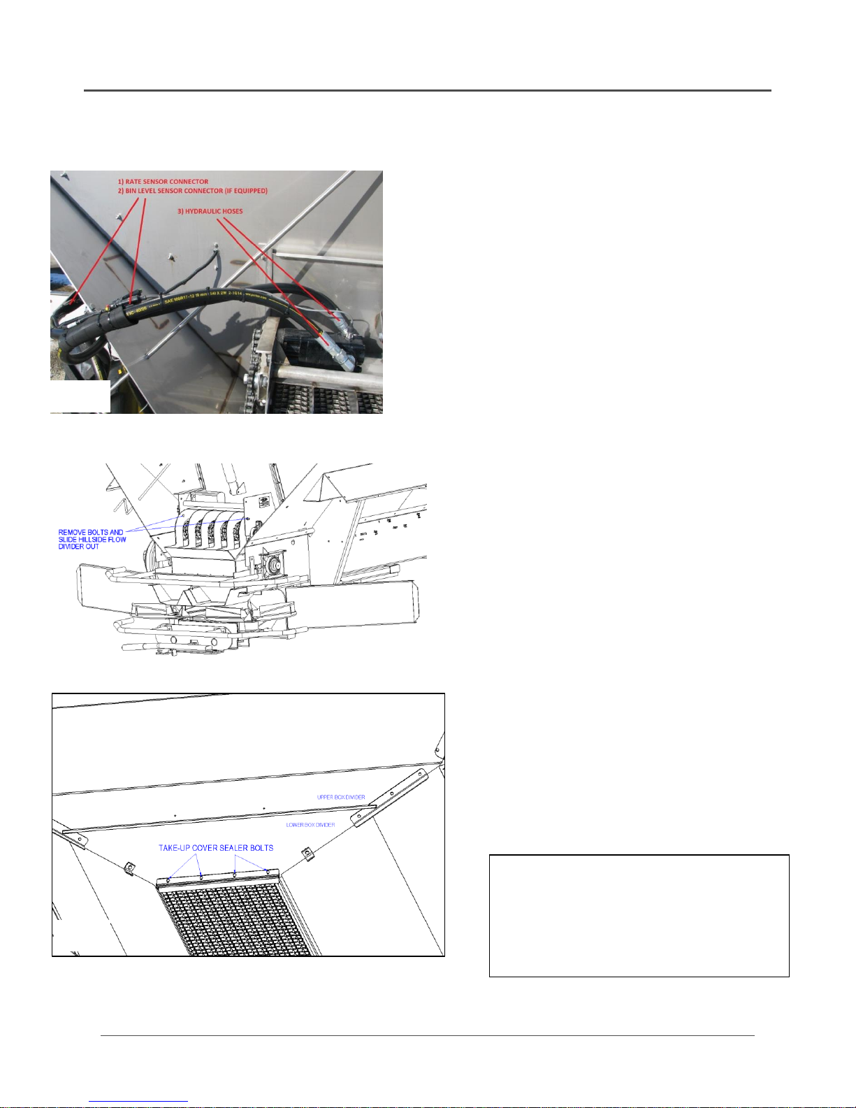
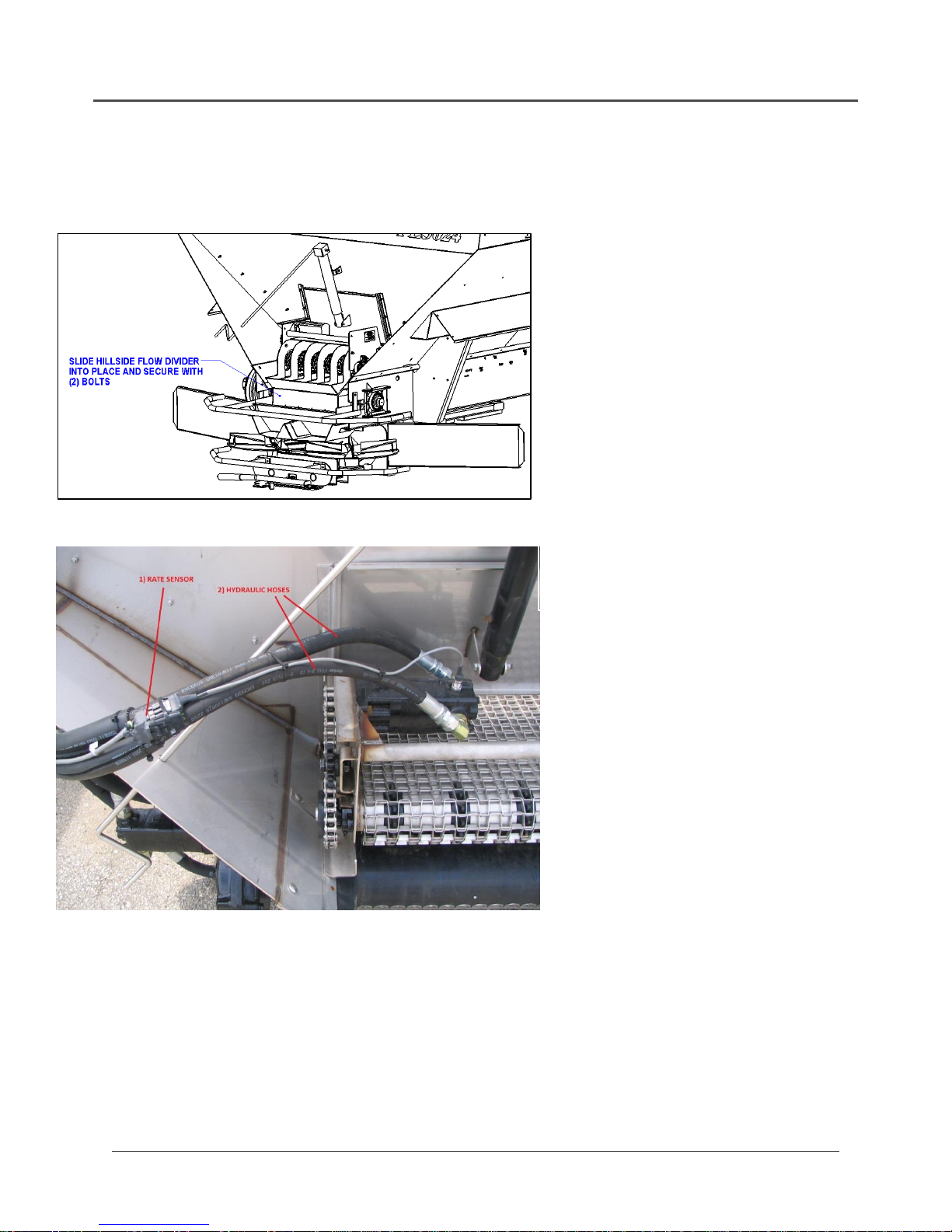
DUO-FORCE REMOVAL
1.) Unplug rate sensor (3 pin connector)
2.) Unplug bin level sensor if equipped
3.) Disconnect hydraulic hoses from motor
(Fig. A) and connect them together.
DO NOT plug the hoses!!
4.) Remove the tab bolts from each side of
the Duo-Force conveyor that are
common with the second-to-last chain
shield bolt on each side.
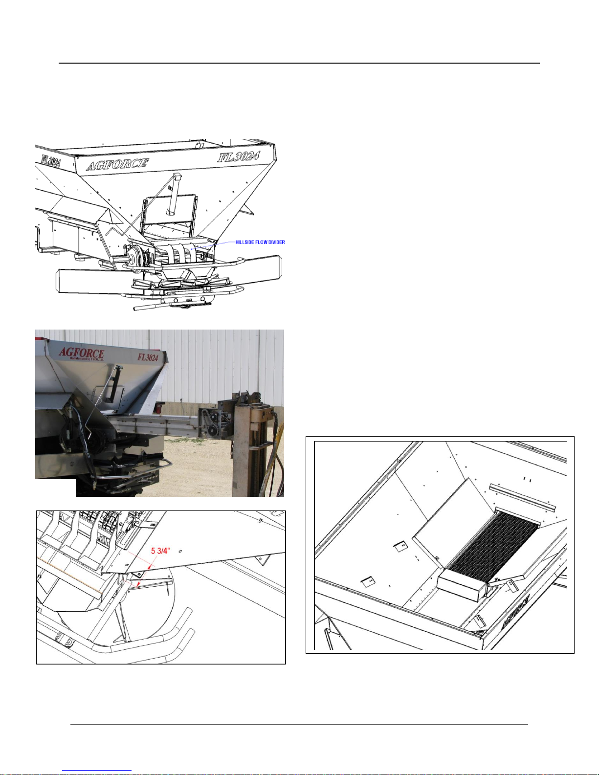
5.) Remove Hillside Flow Divider by
removing (2) bolts at rear of Duo-Force
insert. (Fig. B) Hillside Flow Divider will
then slide out.
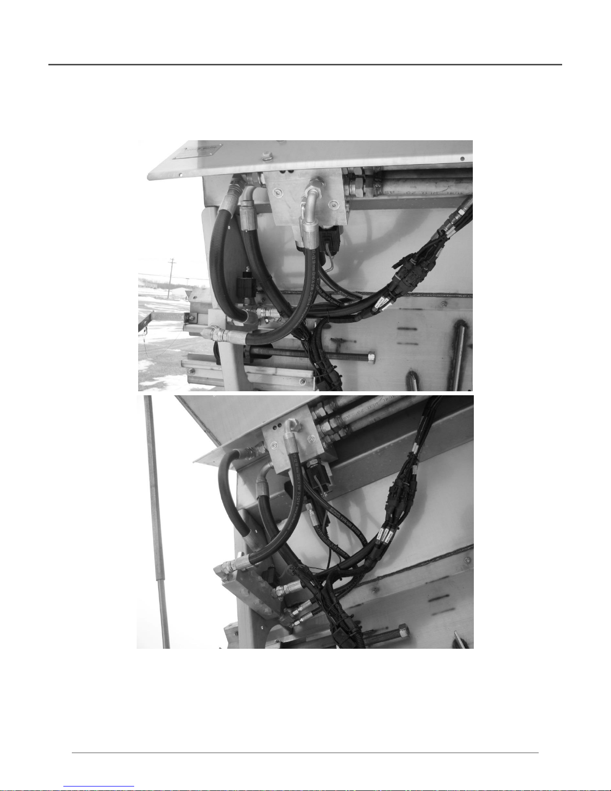
6.) If necessary, loosen the four Take-Up
Cover Sealer bolts to release tension
(Fig. C)
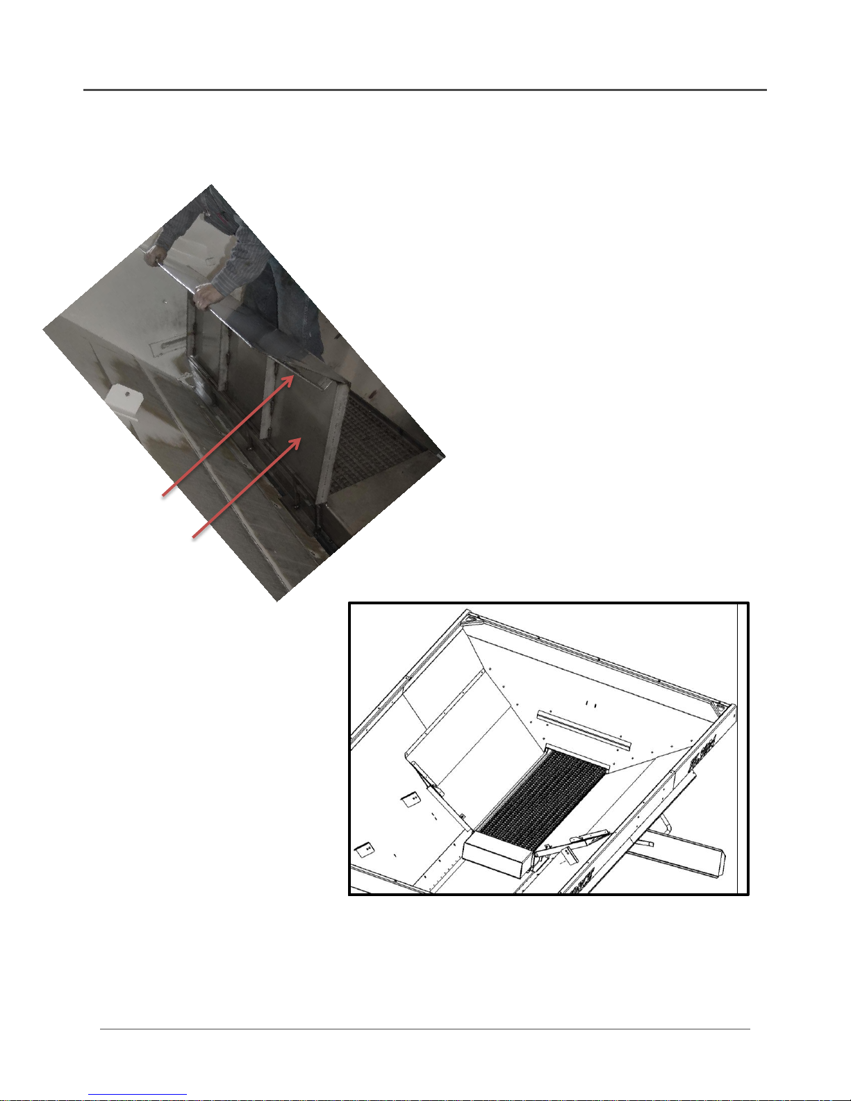
7.) With a second person monitoring from
inside the AgForce box, insert fork truck
forks under the Duo-Force insert and
carefully slide it out (Fig. D)
8.) Remove Hinged Panel bolts to allow
Hinged Panels to swing and lay down
on AgForce box sides (Fig. E)
Fig. A
Fig. B
Fig. C
Note: Inverted “V” removed for clarity
Note: It is not necessary to remove
either Box Divider or the Inverted “V”. If
greater flow is desired, the Lower Box
Divider can be removed.

FORCE UNLTD. SPREADERS * GPS EQUIPMENT * CONVEYORS
HOME OF THE “FORCE”FIELD Instructional Pg. 3
DUO-FORCE REMOVAL (Continued)
Fig. D Removing Duo-Force insert with fork truck
Fig. E Removing Hinged Panel Bolts
Inverted “V” removed for clarity
NOTE: Hinged Panels MUST be
re-fastened to the Box Divider
before reinstalling the Duo-Force
conveyor insert
FORCE UNLTD. SPREADERS * GPS EQUIPMENT * CONVEYORS
HOME OF THE “FORCE”FIELD Instructional Pg. 4
Duo-force installation
1.) Open Feedgate all the way and remove
Hillside Flow Divider and its brackets (Fig. A)
DO NOT replace chain shield bolts that were
common to the Hillside Flow Divider brackets
yet
2.) Using a fork truck, insert Duo-Force conveyor
insert (Fig. B)
3.) Slide conveyor insert in so that brackets align
with second chain shield bolt holes. Make
sure that brackets are bolted to conveyor
insert properly (See Instructional Pg. 1).
Measurement from end of Duo-Force
conveyor insert to end of AgForce chain
shield should be 5-3/4”(Fig. C). Replace
chain shield hardware
4.) Place Hinged Panels in box as shown in Fig. D
Fig. A
Fig. B
Fig. C
Fig. D
FORCE UNLTD. SPREADERS * GPS EQUIPMENT * CONVEYORS
HOME OF THE “FORCE”FIELD Instructional Pg. 5
DUO-FORCE INSTALLATION (continued)
1.) Sdg
2.) Asdf
3.) Asdf
4.) Asd
5.) Asdg
6.) Asd
7.) Asdf
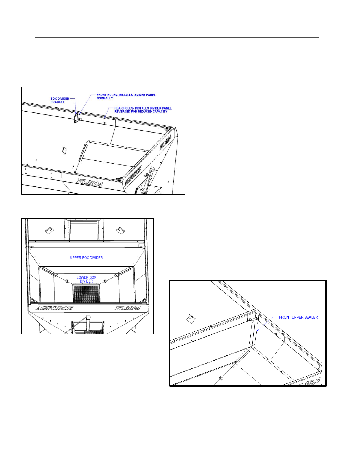
8.) LOOSELY bolt in Box Divider Brackets on
box sides according to desired position of
Box Divider panel using ½” UNC x 1”
button head bolts, ½” flat washers and
nylon lock nuts (2 of ea. per side). Plug
unused set of holes with same style of bolt
(Fig. G)
1.) Asd
2.) A
3.) Asdf
4.) Asdf
5.) Adsf
6.) Asdf
7.) LOOSELY bolt Box Gusset panels to box sides
using 3/8” UNC x ¾” button head screws and
nylon lock nuts (5 per side)
5.) Hook the bent flange of the Hinge Panel under the
“fingers” on the back side of the Box Gusset panel (Fig. E)
Box Gusset
“finger”
Hinged
Panel
Fig. E
6.) Align front edges of Box Gusset and Hinged Panel, and
lay down flat against box sides (Fig. F)
Fig. F Box Gusset Panel Installation
Note: Do not tighten any
hardware down until all
panels, dividers and sealers
have been installed.
FORCE UNLTD. SPREADERS * GPS EQUIPMENT * CONVEYORS
HOME OF THE “FORCE”FIELD Instructional Pg. 6
1.) SF
2.) ASDF
3.) ASDF
4.) ASDF
5.) ASDF
6.) ASDF
7.) ASDF
8.) ASDF
9.) Install Upper & Lower Box Divider
Panels and bolt together using ½”
UNC x 1” carriage bolts, ½” flat
washers, lock washers and ½” UNC
hex nuts (3 of ea.)
10.) LOOSELY bolt Box Gusset panels to
Box Divider panels using ¼” UNC x
1” bolts, ¼” lock washers and ¼”
UNC hex nuts (3 of ea. per side).
11.)LOOSELY bolt Hinged Panels to
Lower Box Divider panel using 3/8”
UNC x 1” bolts, 3/8” flat washers,
lock washers and 3/8” UNC hex nuts
(1 ea. per side)
12.) Install upper Box Divider Sealers
using ¼” UNC x 1” bolts, ¼” lock
washers and ¼” UNC hex nuts (1 ea.
per side)
DUO-FORCE INSTALLATION (continued)
Fig. G Box Divider Bracket Installation
Fig. H Box Divider Panel Installation
Note: Sealer panels are intentionally
under-bent so when properly bolted
down, the sealer holds tightly against the
box side.
Fig. J Upper Box Divider Sealer Installation
FORCE UNLTD. SPREADERS * GPS EQUIPMENT * CONVEYORS
HOME OF THE “FORCE”FIELD Instructional Pg. 7
DUO-FORCE INSTALLATION (continued)
Fig. M
1.) Asdf
2.) Asdf
3.) Asdf
4.) Asdf
5.) Asdf
6.) Asdf
7.) Asdf
8.) Asd
9.)
10.) Asdf
11.) Asdf
12.) Asdf
13.) Install Take-Up Cover Sealer to Lower Box
Divider panel using ¼” UNC x 1” bolts, ¼”
lock washers and ¼” UNC hex nuts (4 of ea.)
14.) Remove third bolt from each Feedgate
Slide and eight bolts plugging unused holes
on the rear panel if present and set aside
(Fig. K)
15.) Install Rear Sealers using hardware
removed, or ¼” UNC x 1” bolts, ¼” lock
washers and ¼” UNC hex nuts (5 of ea. per
side) (Fig. L)
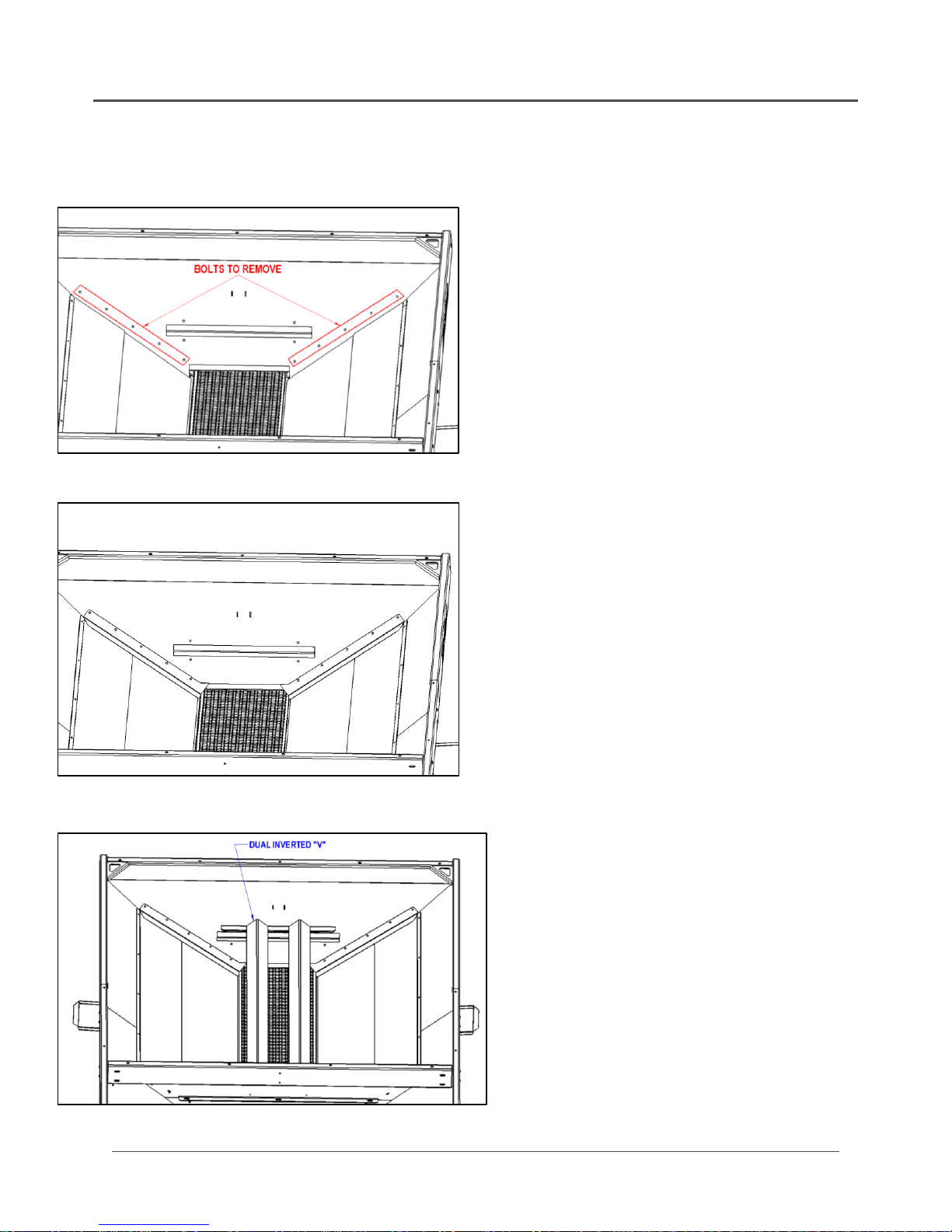
16.) Remove top Feedgate Slide bolts and set
aside
17.) Install Dual Inverted “V” (Fig. M). The 90-
degree mounting flange bolts to the Upper
Box Divider panel, and the over-bent
mounting flange bolts to the rear box panel
through the top Feedgate Slide bolt holes.
Reuse Feedgate Slide hardware for the
rear, and use ¼” UNC x 1” bolts, ¼” lock
washers and ¼” UNC hex nuts (2 of ea.) for
the front.
18.) Securely tighten all bolts from previous
steps. Be sure that all panels and sealers
are secure, as well as the conveyor
mounting straps from Step 3.
19.) Caulk around any gaps between sealers
and/or panels as necessary
Fig. K Bolt Removal
Fig. L Rear Sealers Installed
FORCE UNLTD. SPREADERS * GPS EQUIPMENT * CONVEYORS
HOME OF THE “FORCE”FIELD Instructional Pg. 8
DUO-FORCE INSTALLATION (continued)
1.) Ads
2.) Asd
3.) Asdf
4.) Asdf
5.) Asdf
6.) Asdf
7.) Asdf
8.) Asdf
9.) Asdf
10.) Asdf
11.) Asdf
12.) Asfd
13.) Asdf
14.) Asdf
15.) Asdf
16.) Asdf
17.) Asdf
18.) S
19.) S
20.) Install Hillside Flow Divider by
fitting slotted holes on to conveyor
insert pegs. Secure with 3/8” UNC x
1” bolts, 3/8” lock washers and 3/8”
UNC hex nuts (2 of ea.)
21.)Plug in electrical connector for rate
sensor and for bin level sensor (if
equipped)
22.) Disconnect Duo-Force hoses from
each other and connect to fittings
on Duo-Force conveyor motor
Fig. N Hillside Flow Divider Installation
FORCE UNLTD. SPREADERS * GPS EQUIPMENT * CONVEYORS
HOME OF THE “FORCE”FIELD Instructional Pg. 9
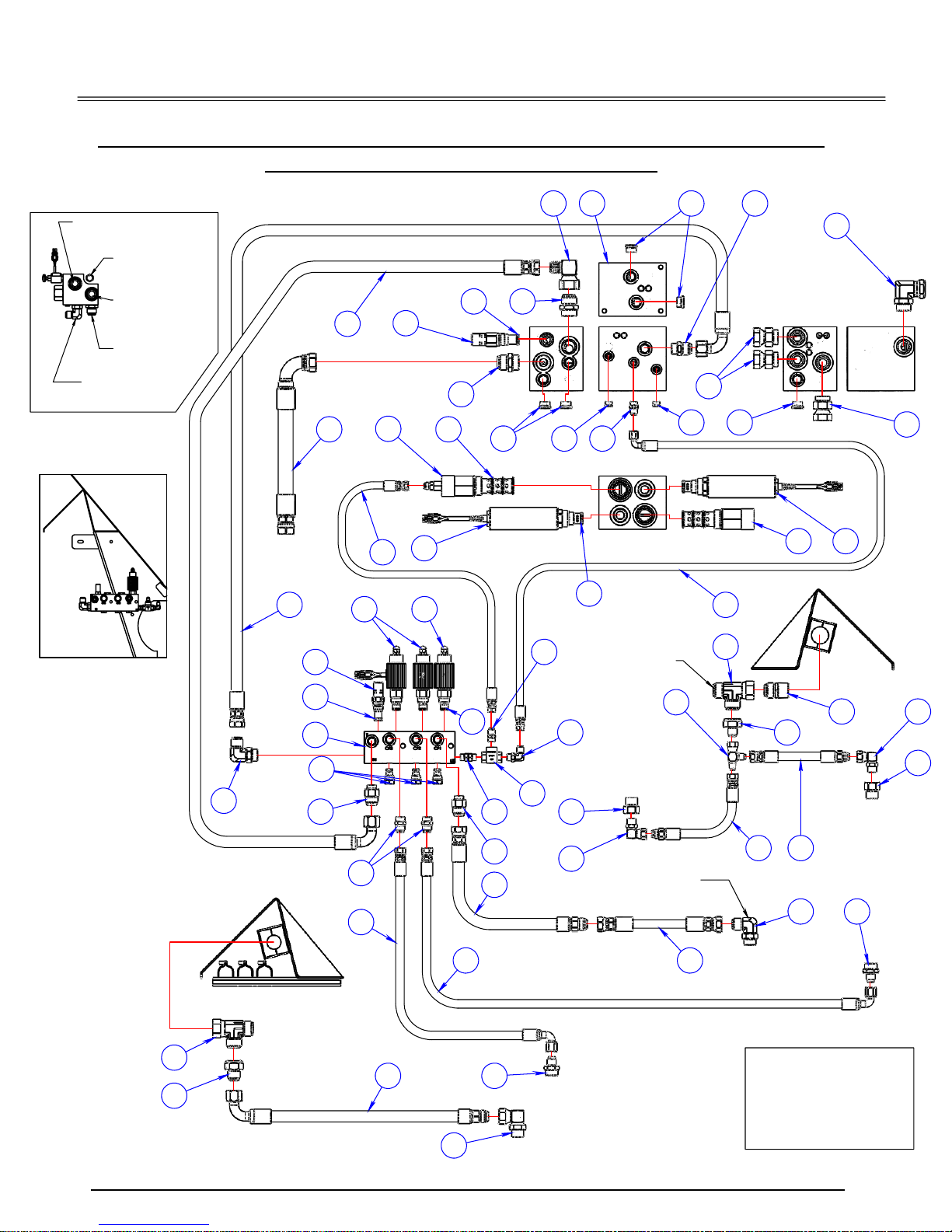
Agforce valve block configuration
With duo-force
Note: This page is for visual reference only.
For details, see Parts Page DF-1.1
PASS. SIDE
REAR
DRIVER'S SIDE
REAR
ROUTE HOSE UNDER BOX IMMEDIATELY IN FRONT OF SPINNER ASSY
TO RETURN PORT ON REAR
OF DUO-FORCE MOTOR
TO PRESSURE PORT ON TOP OF
TRI-FORCE MOTOR (DRIVER'S SIDE)
TO RETURN PORT
ON TOP OF QUAD
FORCE MOTOR
(PASS. SIDE)
TO RETURN HOSE
FROM CONVEYOR
MOTOR TEE
TO PUMP
TO RETURN HOSE
FROM CONVEYOR
MOTOR TEE
TO PRESSURE PORT ON BOTTOM OF QUAD FORCE MOTOR (PASS. SIDE)
TO RETURN PORT
ON BOTTOM OF
TRI-FORCE MOTOR
(DRIVER'S SIDE)
TO PRESSURE PORT ON FRONT
OF DUO-FORCE MOTOR
4
3
2
3
7
7 17
162
12
9
8
10 1
5 6A
6
2
8
13
18 1114
20
19
21
29
15
22
30
26
27
49
43 31
2332
38
39
40
41
42
42
41
43
38
47
46
45
24
25
51
44
48
28
44
31
33
35
50
37
36
34
**CONNECT HOSES 23 & 25 WHEN
REMOVING QUAD FORCE
**CONNECT HOSES 32 & 51 WHEN
REMOVING TRI-FORCE
**CONNECT HOSES 45 & 46 WHEN
REMOVING DUO-FORCE
RETURN FLOW TO MAIN VALVE
BLOCK (IN PLACE OF ITEM #10)
POSITION OF RELIEF
VALVE IN MAIN BLOCK
(ITEM #9)
PRESSURE INLET,
CONNECT ITEM #14
TO PRESSURE PORT
ON MAIN BLOCK
(IN PLACE OF ITEM #8)
RETURN, CONNECT HOSE
#20, REMOVE ITEM #10
MULTIBIN VALVE BLOCK
(ITEM #34) MOUNTS TO
THE FRONT DRIVER'S
SIDE BOX GUSSET AS SHOWN
HOME OF THE "FORCE" FIELD Pg. QF-1.1
CONNECTIONS FOR UNITS
W/ DUMP VALVE
force unltd.
agforce w/ duo-force,tri-force & quad force hydraulic
setup w/ multibin valve block
SPREADERS*GPS EQUIPMENT*CONVEYORS

FORCE UNLTD. SPREADERS * GPS EQUIPMENT * CONVEYORS
HOME OF THE “FORCE” FIELD Pg. DF-1.2
DUO-FORCE HYDRAULIC SETUP PARTS KEY
CONTINUED
ITEM PART NO. DESCRIPTION QTY.
1 1211-00 Main Valve Block - Hydraulic 1
2 1202-119 Plug 5
3 1202-117 Adapter - Straight 3
4 1202-210 Adapter - Elbow 1
5 1211-80 Cartridge - PSI Compensator 1
6
6A
1211-01A
1211-011A
Valve - Hydraulic Servo
Valve – PWM - Conveyor
2
2
7 1202-118 Plug 2
8 1202-116 Adapter - Straight 1
9 1211-945 Valve - Hydraulic Relief 1
10 1202-1800 Adapter - Elbow 1
11 1211-80K Seal Kit As Req’d
12 1211-95K Seal Kit As Req’d
13 1211-01K Seal Kit As Req’d
14 1207-131 Hose Assembly 1
15 1211-0820 Check Valve 3
16 1202-109 Adapter - Straight 1
17 1211-605 Check Valve 1
18 1211-801 Modified Cartridge - PSI Compensator 1
19 1207-601 Hose Assembly 1
20 1207-602 Hose Assembly 1
21 1207-603 Hose Assembly 1
22 1207-604 Hose Assembly 1
23
24 1207-606 Hose Assembly 1
25
26 1211-94 Valve - Hydraulic Relief 1
27 1211-94K Seal Kit As Req’d
28 1211-081 Valve Plug Cartridge 2
29 1211-08A Proportional Valve 1
30 1211-08K Seal Kit As Req’d
31 1202-1090 Adapter - Straight 2
32 1202-1180 Plug 2
33
34 1211-001
1200-310
1209-40
1209-42
1205-21
Multi-Bin Valve Block - Hydraulic
Requires:
Hex Head Bolt - 3/8” UNC x 3” MS
Flat Washer - 3/8” MS
Lock Washer - 3/8” MS
Hex Nut - 3/8” UNC MS
1
2
6
2
2
35 1202-25 Adapter- Straight 1
36 1222-7 Shuttle Valve - Remove Ball 1

FORCE UNLTD. SPREADERS * GPS EQUIPMENT * CONVEYORS
HOME OF THE “FORCE”FIELD Pg. DF-1.3
Duo-force hydraulic setup parts key (continued)
ITEM
PART NO.
DESCRIPTION
QTY
37
1202-2056
Adapter- Elbow
1
38
1202-3015
Adapter- Tee
1
39
1202-102
Adapter- Straight
1
40
1
41
1
42
1
43
1202-202
Adapter- Elbow
2 w/o Dump Valve
3 w/ Dump Valve
44
45
1207-15
1207-16
1207-17
Hose Assembly (12’ Box)
Hose Assembly (13’ Box)
Hose Assembly (14’ Box)
1
46
1207-18
Hose Assembly
1
47
1202-1035
Adapter- Straight
1
48
1202-2095
Adapter- Elbow
1
49
50
1202-1074
Adapter- Straight
1

FORCE UNLTD. SPREADERS * GPS EQUIPMENT * CONVEYORS
HOME OF THE “FORCE”FIELD Pg. DF-2
DUO-FORCE CONVEYOR DRIVE
ITEM
PART NO.
DESCRIPTION
QTY.
1
1217-99
Drive Sprocket
Requires:
Set Screw- 5/16” UNF x 5/16” Lg.
Key Stock- ¼” Sq. x 1”
1
2
1
2
1217-30
1200-350
1209-61
1209-63
1205-36
Pillow Block Bearing
Requires:
Set Screw- 5/16” UNF, 5/32” Hex
Hex Head Bolt- ½” UNC x 1-1/2” SS
Flat Washer- ½” SS
Lock Washer- ½” SS
Hex Nut- ½” UNC SS
2
2 ea.
2 ea.
2 ea.
2 ea.
2 ea.

FORCE UNLTD. SPREADERS * GPS EQUIPMENT * CONVEYORS
Duo-force conveyor drive (continued)
ITEM
PART NO.
DESCRIPTION
QTY.
3
1217-45
1220-144
Sprocket- Flat Wire Belt
Requires:
Key Stock- ¼” Sq. x 1-1/2”
Set Screw- 3/8” UNF x 3/8”
4
1 ea.
2 ea.
4
1233-61
Drive Shaft
1
5
1208-92
Pipe Clamp & Hardware
1
6
6
1233-1045
1233-1045 XLG
Conveyor Frame- Duo-Force & Duo-Force LTD
Conveyor Frame- Duo-Force XLG (18’ Box)
1
1
7
1213-145
1220-144
1200-403
1209-63
1205-36
1213-145 SK
Hydraulic Motor
Requires:
Key Stock- ¼” Sq. x 1-1/2” Lg.
Socket Head Cap Screw- ½” UNC x 1-1/2” Lg.
Lock Washer- ½” SS
Hex Nut- ½” UNC SS
Seal Kit
1
1
4
4
4
1
8
1217-995
Sprocket- Idler
Requires:
Hex Head Bolt- 5/8” UNC x 2” M/S
Flat Washer- 5/8” M/S
Nylon Lock Nut- 5/8” UNC M/S
1
1
1
1
9
1217-960
Sprocket- Motor
10
1233-60
Roller Chain w/ Connector
Requires:
20 Links
1
11
1233-40
1205-51
Weldment- Take-Up Bracket
Requires:
Hex Nut- 5/8” UNC M/S
1 LH, 1 RH
2 ea.
12
1233-42
Snub Roller Shaft
1
13
1233-41
Snub Roller
3
14
1233-10
1200-302 SS
1209-41
1209-43
1205-27
Conveyor Mounting Strap
Requires:
Carriage Bolt- 3/8” UNC x 1” SS
Flat Washer- 3/8” SS
Lock Washer- 3/8” SS
Hex Nut- 3/8” UNC SS
2
1 ea.
1 ea.
1 ea.
1 ea.
15
1233-1
Flat Wire Belt- Duo-Force & Duo-Force LTD
Flat Wire Belt- Duo-Force XLG
As Req’d-
Specify Length
16
1233-2
Connecting Rod- Flat Wire Belt
1
Table of contents
Popular Farm Equipment manuals by other brands

Schaffert
Schaffert Rebounder Mounting instructions

Stocks AG
Stocks AG Fan Jet Pro Plus 65 Original Operating Manual and parts list

Cumberland
Cumberland Integra Feed-Link Installation and operation manual

BROWN
BROWN BDHP-1250 Owner's/operator's manual

Molon
Molon BCS operating instructions

Vaderstad
Vaderstad Rapid Series instructions


