Force NRG Series User manual

Part No 60121508 Rev E 1 Instructions, Force NRG Customer Assembly
READ THIS BEFORE UNPACKAGING YOUR PRODUCT!
COMPONENT VERIFICATION CHECKLIST
AND ASSEMBLY INSTRUCTIONS
O
–HOLE PUNCH TO ATTACH
DOCUMENT TO DRIVETRAIN

Part No 60121508 Rev E 2 Instructions, Force NRG Customer Assembly
QA TO PLACE SERIAL LABEL HERE
FORCE NRG SERIES ASSEMBLY
NOTE: SOME IMAGES USED ARE FOR REFERENCE ONLY.
Serial Number Sticker:
To Get Started:
1) Remove several pieces of the packaging foam and place them on top of
a large surface/table (at least 6’x 4’) to protect the parts from damage
and scratching once removed from the box. It is recommended to use a
table and have a second person to make assembly easier
2) Remove the drive train assembly and place on foam
3) Remove the frame assembly and backrest and place on foam
4) Unseal the part boxes to reveal the “Small Component Bags”, which
should include small components and “Small Component Verification
Sheets”, as well as some of the large components below.
a. NOTE: Some boxes may be empty which are used as filler material in
packaging
5) Remove both batteries and charging port from the SRAM accessory box
and begin charging the derailleur batteries while you assemble the
handcycle
6) Use the “Large Component and Accessory” verification checklist below
to verify that all major components are present.
7) Once you’ve confirmed that all large components are present, proceed
to the “Small Component Verification” step.
a. If you discover any components are missing, please contact our Customer
Service Department with your serial number and the Part Number/Description
Large Component Verification and Accessory Checklist (QA
and Customer):
QUALITY CHECKLIST CUSTOMER CHECKLIST
1) Frame Assembly (1)
2) Drivetrain (1)
3) Crank Arm with Handpedal (1)
4) Footrests (2)
5) Backrest (1)
6) Rear Wheels (2)
7) Bumper (found in wheel box) (1)
8) Positioning Strap (1)
9) Safety Flag (1) found in Wheel Box
10) Accessories (if applicable)
11) Small Component Bags with Verification Sheets (4)
QA Signature & Date:
________________________________________

Part No 60121508 Rev E 3 Instructions, Force NRG Customer Assembly
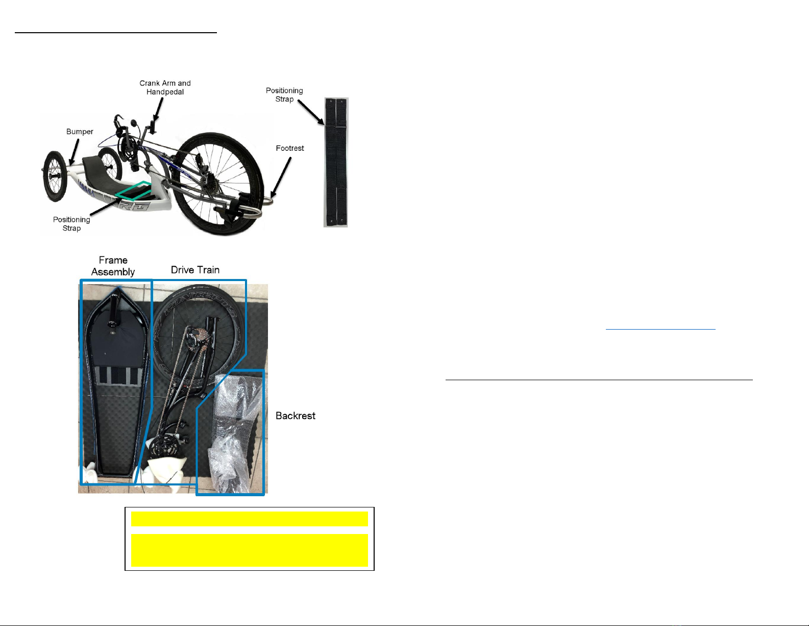
Small Components and Verification
1) For each “Small Component Bag” (1-4), remove the verification sheet
and lay out on a flat level surface.
2) Remove small components from bag and place them on the verification
sheet in their outlined areas
a. NOTE: From hereon we will refer to the “Small Component
Verification” sheet and their associated components by the
sheet number located at the top right-hand corner of the page.
3) Once you’ve confirmed that all small components are present. Proceed
to the assembly instructions
4) If you discover any components are missing, please contact our
Customer Service Department with your serial number and the Part
Number / Description of the missing component(s).
topendorders@invacare.com
Preparing for Assembly
1) Your product has shipped with the basic tools required to assemble
your product. We do recommend you also have the following tools to
optimize the assembly process
a. Sharp Scissors or Side Cutters
b. Torque Wrench
c. Medium/Large flathead screwdriver
d. Tape Measure
e. Air Pump
f. Some good music, an amusing friend and your drink of choice…
Are you ready? Cool… Let’s do this.
1. Fork and Frame Assembly
a. Take the steer tube assembly from [SHEET #2]
b. Remove top end cap, top headset cap, upper crown race ring,
upper dust ring and top bearing from steer tube assembly –
leaving lower headset assembly components in-tact.
c. Install the steer tube assembly into the frame following Figure
D. Once installed, position the steer tube with approximately 2”
protruding out from the bottom of the headtube.
d.
e. Reinstall the upper headset assembly components following
figure D. You will need to ensure that the headset components
are positioned as closely to the head-tube as possible. If done
correctly, you should no longer be able to see the bearings. You
can also use the “Small Component Verification” sheet for a
more detailed view of the component orientation.
i. NOTE: Dust rings have a taper on the inside of one
side. The taper should be against the race ring and the
flat side against the bearing.
f. Take the packing insert which the drivetrain front wheel was
secured in and place it under the front of the frame to raise the
steer tube from your work surface a couple of inches. If
assembling on a large table, positioning the frame so that the
steer tube is at the edge of the table will negate the need to
prop up the front of the frame
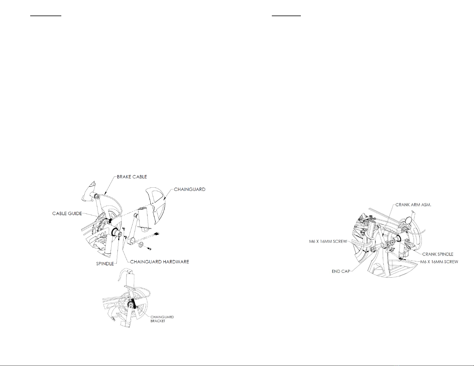
g. Install the drivetrain to the frame using 5mm Allen Key from
[SHEET #1] and fork hardware from [SHEET #2].
h. Rotate fork clamps open (see next page, line “ii”) and place the
fork onto the steer tube. With the fork in place, rotate the
clamps closed. If having difficult closing the clamps, make sure
the clamps are positioned so that they clear the headset
assembly
i. NOTE: This is the most difficult part, after this it’s
smooth sailing. If you’re having difficulty getting both
clamps to close –it is because the tolerances between
the two clamps is very tight for performance reasons.
It is recommended to get the bottom clamp closed
with hardware finger tightened and then have that

Part No 60121508 Rev E 4 Instructions, Force NRG Customer Assembly
amusing friend of yours pull down and back (see next
page, line “iii”) simultaneously on the fork while you
snap the top clamp closed. Here a picture to that
shows what we’re talking about
ii.
iii.
i. Install and finger tighten the clamp hardware. Install the flat
side of the square nut down on the top of clamp and the split
washer/screw from the bottom of the clamp. This will hold the
drivetrain secure on the steer tube.
j. Tighten the upper and lower endcaps to center the steer tube
between ends of each clamp. This will also compress the
headset
i. NOTE: Verify there is a small gap between the steer
tube and the end caps on both the top and bottom of
the assembly. If not, you can pull the steer tube
up/down by tightening the cap on the opposite end
and losing the cap on the end you’re pulling away
from. If you’re having difficulty making this
adjustment, you may need to loosen the clamp
hardware so that the steer tube can move.
k. After both end caps are tightened, tighten the fork hinged
clamps (recommended torque: 8-9 N.m.)
l.
m. Install dampener hardware from [SHEET #2] with the 13mm
wrench and 7/64” Allen key from [SHEET #1]
n. Install and finger tighten the M8 X 16mm Screw with the M8
Washer
o. Install the 6-32 x 1/2" screws. Hold the drivetrain straight in-line
with the frame. Use the 7/64” Allen Key to adjust the screws
until the dampener holds the drivetrain straight in-line with the
frame on its own
p. To secure the dampener, hold the rubber dampener to prevent
from rotating/tearing then tighten using the 13mm wrench
q.

Part No 60121508 Rev E 5 Instructions, Force NRG Customer Assembly
2. Chainguard
a. Remove packaging materials from around spindle, attached
crank arm and from around the chainring using a pair of scissors
or a side cutters.
b. Install the chainguard between the chainguard bracket and the
chainrings. Use a 3mm Allen Key from [SHEET #1] to install the
chainguard from [SHEET #4] and hardware from [SHEET #2] as
seen on figure below
c. Starting with the lower screw and washer, finger tighten screw
through the chainguard mounting tab on the fork into the
threaded receiver on the chain guard
d. Locate the black plastic cable guide attached to the brake cable
housing
e. Thread the upper chainguard screw through the cable guide
with the hole located above the cable housing. Then, route it
through the chainguard mounting tab on the fork and finger
tighten the screw into the threaded receiver on the chainguard.
f. Use the 3mm Allen Key to tighten both chainguard mounting
screws
g.
h.
3. Crank Arm
a. Install the crank arm assembly using the hardware from [SHEET
#2] and the 5mm Allen Key from [SHEET #1]
i. NOTE: If screws are already found in crank arm, the
screws on [SHEET #2] are extras (bonus!)
b. Remove the end cap from the spindle using a 5mm Allen Key
from [SHEET #1]
c. Before installing crank arm bolts, slide crank arm over the
spindle.
a. NOTE: You may need to open the crank arm clamp to get it
to slide over the spindle. You can use a flathead
screwdriver to open the clamp by inserting it where the
clamp is split and twisting the screwdriver
b. ANOTHER NOTE: Ensure both crank arms are parallel to
each other (this isn’t an upright bicycle buddy)
c. Using the 5mm Allen Key from [SHEET #1], tighten end cap
until it bottoms out (recommended torque: 8-9 N.M.).
i. NOTE: The trick here is to make sure that both
crank arms are parallel and pointing straight down
to the floor. You’ll need to hold the crank arm on
the opposite side while you tighten the end cap to
keep the spindle from turning.
d.
e. Install the screw into the non-threaded side of the crank
arm clamp. Tighten using that 5mm Allen Key that is likely
no longer on [SHEET #1].

Part No 60121508 Rev E 6 Instructions, Force NRG Customer Assembly
4. Footrest
a. Install the footrests by inserting the long end of the aluminum
loop into the end of the fork and ensure that the cushion inside
the strap is positioned to be in contact with riders leg when
riding the handcycle.
b. Install footrest hardware from [SHEET #2] using the 5mm Allen
Key from [SHEET #1]
c. NOTE: You’re going to want to adjust the location of the
footrests once the bike is fully assembled and you’re able to sit
in the bike. …for now, just estimate the location and tighten the
hardware

Part No 60121508 Rev E 7 Instructions, Force NRG Customer Assembly
5. Backrest to Mainframe
a. Remove packaging materials from the backrest
b. Install the backrest to main frame using backrest mounting
hardware from [SHEET #3] and both 4mm Allen Key and 10mm
Wrench from [SHEET #1]
c. Attach the crescent brackets to the outside of the backrest in
the lowest hole of the backrest and first hole in the crescent
using the M6 x 16mm screws, washers, and lock nuts with the
curve of the crescent as seen in illustration and with the flat
side of the crescent bracket against the backrest. Also, the
nylon insert inside the locknut should visible once the hardware
is tightened. Tighten enough so the crescent links don’t move
on their own but can be moved by gently pushing on them.
Clear as mud? These illustrations should help.
d.
e.
f. Remove the seat cushion from the frame and lay the backrest
onto the seat pan so that the front of the backrest is
approximately 4” from the cross-member of the frame. Ensure
that the backrest is centered between the frame rails. Rotate
the crescents so they are pointing towards the back of the
handcycle. Connect the backrest crescent brackets to the frame
by finger tightening the M6 X 35mm screws, split washers and
¼” plastic spacers from [SHEET #3]
i. NOTE: The number of spacers required depends on the
seat width of the handcycle and which mounting holes
you use on the backrest and crescents once adjusted
to a location that is most comfortable for you. You will
need to exercise judgement on whether spacers must
be added/removed to accomplish desired positioning
while ensuring the crescents are as straight as possible
(as seen looking at the bike head on). It’s
recommended to start with one pair of spacers (one
on each side and go from there)
ii. NOTE: The standard mounting location is in the lowest
hole of the backrest and 6th hole from the bottom of
the bracket
g. Ensure that the frontmost part of the backrest is secured to the
seat pan via Velcro
h. Ensure that the M6-35mm screws are tight after the backrest is
in the desired location using a 5mm Allen Key.

Part No 60121508 Rev E 8 Instructions, Force NRG Customer Assembly
Bumper Installation
i. Remove packaging materials from camber tube at rear of frame
assembly
j. Using the clamps from [SHEET #3] and the 4mm Allen Key from
[SHEET #1], Install the bumper to the handcycle
k. Slide the bumper clamp with flag holder onto the (Rider’s left
hand) bumper receiver
i. NOTE: Clamps can only go on one way with the flange
to the outside of the bumper receiver
l. Slide the other bumper clamp onto the (Rider’s right hand)
bumper receiver
m. Slide the bumper through the clamps into the bumper receivers
n. Once the bumper has bottomed out against the camber tube,
tighten both clamps ensuring that the flag holder remains
vertical. (Recommended torque: 8-9 N.M.)
o.
6. Wheels and Tires
a. Attach the wheels to the rear of the frame using a 10mm Allen
Key or 1/4” Allen Key depending on what make of wheels you
have.
b. Determine which wheel goes on the left vs right side of
handcycle based on the arrow on the sidewall of the tires. It can
be hard to see, but keep looking –it’s there.
c. Insert the axles into the axle receivers in the camber tube
ensuring that axles are going in straight to prevent cross
threading which could damage the axle receivers and/or axles
d. Tighten the axles with the appropriately sized Allen Key
(recommended torque: 15-20 N.M.)
e.
7. Tire Inflation
a. Remove the valve stem cap
b. Loosen up needle to outward position
i. NOTE: Not required for rear wheels
c. Thread on valve stem adapter
d. Inflate tires using a standard Schrader air nozzle with a Presta
valve adapter or a Presta valve nozzle (do not exceed
recommendations embossed on tire). We recommend
approximately 80 psi and then fill to preference)
8. Install Safety Mirror
a. Remove plastic bolt from mirror from [SHEET #4] with a 3mm
Allen Key found on [SHEET #1].
b. Wrap the mirror strap around the top of the fork in the location
of your preference
c. Reinstall the plastic bolt and tighten until mirror is secure

Part No 60121508 Rev E 9 Instructions, Force NRG Customer Assembly
9. Position Strap and Seat Cushion
a. Install the positioning strap using positioning strap hardware
from [SHEET #3] and 4mm Allen Key from [SHEET #1] ensuring
that the Velcro opens to the topside of the handcycle.
Depending on user preference, the long side of the strap can be
installed on either the right or left hand side.
b. The split washer should be on the M6 x 16mm screw before
inserting through the grommet on the inside of the positioning
strap and ultimately into the threaded insert on the inside of
the frame rails
c.
10. Final Safety Check and Batteries
a. Remove battery covers by unlatching the hinged lock. This lock
is located on the bottom side of the derailleurs and rotates
downward when in the unlocked position.
i. NOTE: Always remove batteries and install battery
covers when transporting the handcycle!
b. Install batteries that have been charged into the Chainring and
Cassette Derailleur. The battery life is typically 50-60 hours.
i. NOTE: Always check your battery charge before a ride!
c. Refer to user manual for all associated risks before using a
handcycle.
d. Verify tire inflation
e. Double check that all fasteners are secure
f. Verify braking functions
g. Install safety flag
h. Ensure footrests are adjusted and secured
i. Ensure you have good visibility with safety mirror
11. Rock and Roll!
Table of contents