Forest-Master UWWS User manual

Model: UWWS
IMPORTANT: Read this manual fully before assembly and
use and observe all safety rules and operating instruc-
tions
Forest Master Universal
Woodworking Station

Forest Master Model: UWWS2
Your Product
Thank you for purchasing the Forest Master Universal Woodworking Station. We
hope you are 100% satised with your product but if you have any questions or
queries, please don’t hesitate to contact us:
Forest Master Ltd Tel: +44 (0)191 265 5000
Heaton Website: www.forest-master.com
Newcastle Upon Tyne
NE6 5XB
About Your Product
The Forest Master Universal Woodworking Station is used for milling logs into all
kinds of lumber. A chainsaw is mounted to the chainsaw frame that comprises of
two C-shaped runners and an adjustable support bar. The runners slot onto the
two guide rails of the chainsaw mill, allowing the chainsaw to glide freely along the
horizontal plane, with no movement in the vertical plane, to give the smoothest
and most accurate cut possible. The chainsaw mill can be used in a variety of ways
outlined below:
• Milling slabs of wood from a large log.
• Milling multiple boards by clamping a number of slabs together, turning them
onto the side and milling o the bark on both sides.
• Creating fence posts in a quick and ecient way by drilling bolts into both
ends of the log resting the bolts into the V shaped slots. This allows the log to
be milled, unsecured, rotated 90° re secured and the milled again for all four
sides.
• Clamping a log in the vertical position to mill log coins.
• Used as a sawhorse by placing a log into the four, toothed V shaped sections
and cutting vertically with a chainsaw.
• Attaching the Forest Master Router Bed to the two guide bars to the surfaces
and edges of the wood can be routed (requires extra parts you can purchase
from Forest Master).
• It can also be used as a mitre saw stand by attaching the mounting clamps to
the frame and bolting a mitre saw to the clamps with the M6 coach bolts and
fastenings. Details of this can be found in the mitre saw stand manual.
No matter how you use your workbench, please read the safety instructions and
guidelines before use.

Forest Master Model: UWWS 3
Contents
Title Page
Specications 4
Safety 5
Parts List 6
Assembly 9
Adjustments 14
Operation 18
Warranty 28
Contents

Forest Master Model: UWWS4
Specications
Specications
Maximum Guide Bar Width 680mm
Minimum Guide Bar Width 400mm
Maximum Log Length (Up to 12ft with extension sold
separately)
1450mm
Minimum Log Length 200mm
Maximum Log Width 250mm - 520mm
Maximum Cutting Depth 400mm
Minimum Cutting Depth 15mm
Forest Master Recommendations for Chainsaw Milling
After thorough testing with this product, Forest Master can condently give the fol-
lowing recommendations to achieve the best results when chainsaw milling.
• A ripping chain is required for the best nish due to the acute angle of the cut-
ting blades.
• A low-prole bar can make the cutting process faster, but may have eects on
the nish of the cut.. A low-prole bar has an approximate cut thickness of
6mm whereas a standard 3/8 or .404 bar has a cut thickness of 8mm.
• The slower the cut the better the nish - be patient when milling timber, it
can be a slow process. Forcing the chainsaw can lead to a poor nish or bend-
ing within the bar which leads to the saw becoming stuck or being overworked.
• A chainsaw as little as 52cc can be used for milling but be aware, the more
powerful the chainsaw, the quicker and easier the milling process.
• Ensure the chain blades are always sharp before cutting. They must be sharp in
order to provide an ecient cut.
• The width of the guidebars and chainsaw clamps should be as small as possi-
ble and as close to the wood on each side to produce the best nish. By hav-
ing a lot of free space between the wood and where the chainsaw is clamped,
this gives the chainsaw bar space to ex, causing problems during the cut and
adversely eecting the nish.

Forest Master Model: UWWS 5
Safety
Safety Instructions
These instructions are intended for your safety. Please read them carefully before
using the workbench and retain for future reference.
Before You Start
• Check the box and make sure all the listed parts are included. If not, contact
the retailer for assistance.
• Remove all plastic bags and packaging and dispose of them safely.
• Retain the instruction manual for future reference.
Important Safety Information
• Always check the tightness of nuts and bolts prior to use.
• Make sure the chainsaw mill is positioned on a rm and stable surface before
operating. It is best to position the frame so you are cutting downhill.
• Make sure all the adjustment thumbscrews are tight before cutting.
• Always wear appropriate safety gear; gauntlets, safety glasses, ear protection,
chainsaw trousers, safety boots and a dust mask should always be worn when
operating the chainsaw mill.
• Always start the chainsaw on the ground and then lift onto the guide bars with
your hands away from the throttle trigger - use the support bar above the
chainsaw to lift.
• Never assemble, dismantle or readjust any parts of the chainsaw mill while the
chainsaw is still running.
• Be extremely careful of the chainsaw cutting chain while in use.
• Any bystanders or pets must be a distance of at least 10 metres from the
chainsaw mill when in operation.
• Do not operate under the inuence of drugs, alcohol, medication or if you feel
tired or drowsy.
• Never operate the chainsaw mill in an enclosed area - fumes from the exhaust
contain carbon monoxide which is a toxic, odourless and potentially fatal gas.
• Always turn the chainsaw o before dismounting from the guide bars.
• Always operate with one hand on the support bar and one hand on the
chainsaw.
• Never leave the chainsaw running unattended.
• You must be over the age of 18 to operate the chainsaw mill.
• Don’t overreach when milling - only operate the chainsaw from a comfortable
position.
• Don’t force the chainsaw through the cut - apply some force but ease the
blade through the wood. Over forcing the blade can cause injury and damage
the chainsaw.
The warnings, cautions and instructions referred to in this manual cannot cover
all possible conditions and situations that may occur. It must be understood
that common sense and caution must be applied by the operator when using the
chainsaw mill.

Forest Master Model: UWWS6
Parts List
Part
No.
Name Picture Qty.
1. Base Frame 1
2. Crossbeam 2
3. Guide Bars (1490mm) 2
4. Vertical Guide Bar Support 4
5. Left Chainsaw Clamp 1
6. Right Chainsaw Clamp 1
7. Chainsaw Frame Handle 1

Forest Master Model: UWWS 7
Parts List
Part
No.
Name Picture Qty.
8. Gripping Plates 4
9. Perpendicular Telescopic Slot
(PTS)
2
10. Vertical V-Slot 2
11. Horizontal V Slot 2
12. Vertical Sawhorse 2
13. Horizontal Sawhorse 2
14. Step Gauge 1

Forest Master Model: UWWS8
Part No. Name Qty.
15. M8 Hex Bolt 8
16. M8 Cap Head Bolt 8
17. M8 Washer 24
18. M8 Nyloc Nut 16
19. M8 Thumbscrew 16
20. Mounting Clamps (Use with Mitre Saw) 2
21. M6 Coach Bolt (Use with Mitre Saw) 4
22. M6 Washer (Use with Mitre Saw) 4
23. M6 Spring Washer (Use with Mitre Saw) 4
24. M6 Nut (Use with Mitre Saw) 4
Parts List

Forest Master Model: UWWS 9
Assembly
Assembly of the Frame
1. Open the legs of the frame (1) by pressing the pin
on the side of the frame and folding out the legs un-
til the locking pins click into place in the corresponding holes.
NOTE: For the next two steps it is essential that the bolts are loosely fastened
to allow for movement between the materials. This is so that the guide bars can
be calibrated and then tightened later to allow for smooth telescopic adjust-
ment in use.
2. Bolt the two crossbeams (2) to the base frame (1) with the middle telescopic
slots inwards, using the M8 hex bolts (14), M8 washers (16) and M8 nyloc nuts
(17). Two washers should be used for each bolt, one in between the crossbeam
and the frame and one in between the frame and the nut.
REMEMBER: bolts should be loosely fastened.

Forest Master Model: UWWS10
Assembly
3. Bolt the vertical guide bar supports (4) to the guide bars (3) by threading the
M8 cap head bolts (15) through the large holes of the guide bars to fasten into
the small holes and the plate of the vertical guide bars. The M8 cap head bolts
should situate inside the guide bars and be fastened on the outside with the M8
washers (16) and M8 nyloc nuts (17).
REMEMBER: bolts should be loosely fastened.

Forest Master Model: UWWS 11
Assembly
4. Slide the assembled guide bars (3, 4) into the telescopic slots on the outside of
both cross beams (2), making sure the large holes on the guide bars are facing
outwards and the nuts are facing inwards. Drop both guide bars half way down,
using the full height of the smaller side of the step gauge (19) (pg. 14) and
tighten all four thumbscrews on the slots to lock in place.

Forest Master Model: UWWS12
Assembly
5. Make sure the guide bars are the exact same height from the cross beams at all
four supports and then tighten all the loose bolts, starting with the crossbeams
and then the vertical guide bar supports. This should calibrate the guide bars to
allow for smooth vertical adjustment.
6. All the attachments are available to be mounted as desired in the telescopic
slots found in the middle of the crossbeams and at the end of the dual rails
(see adjustments and setup section).

Forest Master Model: UWWS 13
Assembly of the Chainsaw Frame
1. Loosen the thumbscrews on both the left chainsaw clamp (5) and the right
chainsaw clamp (6) and slide them onto the chainsaw frame handle (7) so that
they are facing the same way.
2. Loosen the two M8 nuts on both chainsaw clamps so that you can slide your
chainsaw bar in between the two serrated plates inside the clamps so that the
chainsaw frame handle is situated behind the chainsaw. Make sure the serrated
plates rest only on the bar of the chainsaw and not the chain nor the sprocket
on the nose of the bar.
3. Slide the clamps along both the chainsaw frame handle and the chainsaw bar
itself to the desired position and then tighten the thumbscrews and the M8
bolts on both clamps.
4. Check the chain can move freely through both clamps by manually turning the
chain.
Assembly

Forest Master Model: UWWS14
Adjustments
Setup and Adjustments
Setting the Height of the Guide Bars
For the height to be set correctly, the guide bars need to be of equal distance from
the crossbeams at all four vertical guide bar supports. This can be done one guide
bar at a time.
• To do this, loosen the thumbscrews on the crossbeams for the two vertical
supports of the guide bar, so that it can move freely up and down the in slots.
• Place the step gauge in between the upper section of the crossbeam and the
guide bar and make sure the at edge of the step gauge is ush with the cross-
beam.
• Drop the guide bar down onto the step gauge at the step that is the desired
height and tighten the thumbscrew. Repeat for the other vertical support of the
same guide bar. Then do the same process for the second guide bar and make
sure the height is the same at all four vertical supports.
• You can make your own gauges for specic heights you may require by cutting
blocks of wood down to size and using them in the same manner.
• The lowest the guide bars can be set is the smallest step on the gauge. If thin-
ner cuts are required then move the gripping plates underneath the wood up to
suit.
Forest Master Model: UWWS 15
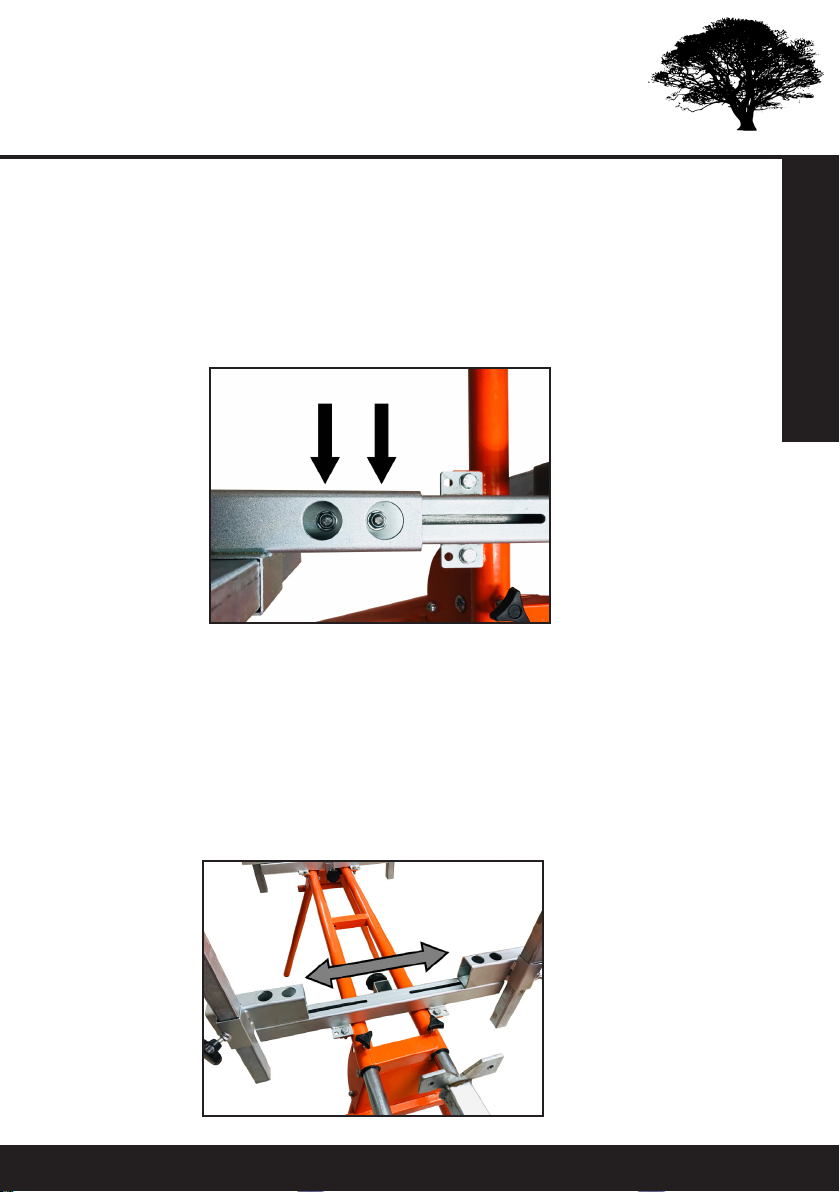
Width Adjustment
The width of the guide bars is adjustable by sliding the upper sections of the cross-
beams inward and outward to the desired position. This requires a 13mm socket
with a depth of at least 60mm.
• Loosen the two M8 nuts on the inside of each upper section by threading the
socket through the holes. NOTE: they only need to be loosened by a couple of
turns so that the section can move - do not fully take the nut o the bolt.
Adjustments
• Measure the width the guide bars need to be in order to t your specic chain-
saw bar. You must allow the space for both clamps and the nose sprocket to
be on the outside of the guide bars. It is easier to measure of you have already
assembled the chainsaw frame.
• Make sure the distance from the middle is the same for both upper sections
and crossbeams and retighten the M8 nuts to secure in place.
• Small adjustments can be made on the chainsaw clamps themselves by read-
justing the position on the chainsaw bar so that the C-Sections t perfectly on
the guide bars.

Forest Master Model: UWWS16
Adjustments
Clamp Setup
The height of the C-Section underneath the left and right chainsaw clamps needs to
be set in accordance with the size of the guide bars.
• To do this, loosen the two M6 nuts found on the side of both chainsaw clamps,
so that the lower plate can move up and down freely in the grooves.
• Slot the C-Sections onto the guide bars and position the chainsaw frame so that
it is perpendicular to the guide bars.
• Move the lower plate of the C-Section up so that it lightly clamps the guide bar
and then tighten the two M6 nuts on the side to secure. It needs to be tight
enough to the guide bars so that it cannot tilt or jump, but not so tight that it
is dicult to move the chainsaw along the guide bars. Move the chainsaw along
the guide bars to test the ease of movement before performing any cuts.

Forest Master Model: UWWS 17
Gripping Plates and Attachments
The gripping plates and attachments t into the telescopic slots in the middle of
the crossbeams and at the end of the dual rails. You can also add the perpendicular
telescopic slot (PTS) so that the gripping plates and attachments can be used in a
horizontal plane.
• The gripping plates have four holes for screws to pass through and grip into
the log to secure it in place. They can be used to grip the underside of he log
or used with the PTS to grip the ends of the wood. We recommend using M6
anged head coach bolts to screw into the wood. This is because normal Phil-
lips wood screws will be rounded after constant use. The screws also do not
need to be particularly long, 50mm is enough as they are only there to hold the
wood in place.
• The V-Slots and sawhorse attachments are used in the same manner and the
specics of which can be found in the operation section. The horizontal ver-
sions of the attachments are to be used with the PTS.
Adjustments

Forest Master Model: UWWS18
Operation
Operation
This section explains how to operate the chainsaw mill and the dierent processes
which can be performed on the frame for all types of work.
Mounting the Log
There are a few techniques that can be used to mount the log to the frame depend-
ing on the size and weight of the log.
• For manageable logs and timber, they can be simply lifted and placed so that
it rests on the two crossbeams. It is easier to have the guide bars as low as
possible or removed, so you don’t need to lift over them.
• For heavier logs, you can lift one end at a time and place each end on the
crossbeam. You will need to remove the guide bars for this method. To help
even further, you can position some trestles next to the frame to act as a step
so that you only lift half the height at a time for each end of the log.
• For very large or heavy logs, fold the legs in, turn the frame upside down and
place on top of the log. Then secure the frame to the log by screwing into it
through the gripping plates. The log can now be rolled over by hand or with
a log peavey so that the frame sits upright. It is usually best to perform the
rst few cuts on the oor to take some weight o the log before extending the
frame.
Securing the Log
The log can be secured to the frame through the four gripping plates enabling the
user to grip from underneath and the ends of the log by screwing wood bolts into
it - We recommend using M6 anged head coach bolts.
• When using the PTS, it is better to have the dual rails extended as little as pos-
sible for stronger securing.
• We suggest using two bolts for each gripping plated used. This is because the
more secure the log, the less it can move during the cut and therefore the bet-
ter the nish.
• The logs can also be secured through the two holes either side of the V on the
V-Slot when cutting fence posts.

Forest Master Model: UWWS 19
Operation
Performing Cuts with the Chainsaw
Before performing any cuts make sure all adjustable components of the chainsaw
mill and frame are tight and secure and the guide bars are the same distance from
the crossbeams at all four vertical supports.
• Cuts can be performed with the legs folded out and the stand at full height or
the legs folded in and the stand at a lower height, resting on the bottom of the
frame.
• It is best to perform cuts with the frame on a downhill angle so that gravity aids
the force of the cut.
• Start your chainsaw on the oor rst and then lift by the frame handle to slot
the C-Sections into the two guide rails. DO NOT lift with a hand on the throttle,
this could be very dangerous.
• Once the chainsaw is in position, you can start the cut. Run the chainsaw before
contact with the wood and then gently push the chainsaw by the frame handle
and the throttle handle through the wood.
• Push with enough force to ease through the cut but not so much that you
overwork the chainsaw. Patience is required when milling as it can be a slow
process. You cannot force the chainsaw too hard as it can jam in a downward
motion and get stuck, ruining the nish of the cut.
• The C-Sections have two spacers inside them to allow the chainsaw to tilt in the
horizontal plane. This allows the chainsaw to tilt in a ‘see-saw’ action as you
work your way through the cut, which is especially useful when encountering
knots.
• When you reach the end of the cut, turn o your chainsaw whilst the frame is
still mounted to the guide bars and then dismount the chainsaw frame from the
guides.
• Make sure all wood that has been cut is removed from the log before starting
the next cut.

Forest Master Model: UWWS20
Operation
Milling Slabs
To cut your wood into slabs, it is important that the wood is always resting on the
crossbeams and secured using all four gripping plates. We advise to use the two
vertical gripping plates in the crossbeam slots and the PTS with the other two grip-
ping plates to secure both ends from the dual rails.
• Set the guide bars to a height that can take the top of the bark o the full log,
making sure that the width of the second slab (beneath the cut) is as desired.
• Perform the rst cut following the cutting instructions.
• Once the cut has been completed, the guide bars need to be dropped to the
next position. The distance the guide bars are moved down will equate to the
thickness of the next slab. Therefore, you can do this with the step gauge or
measure it yourself for your own desired thickness.
• Then perform the next cut to complete the slab. The last two steps can be re-
peated until the log has been completely cut down.
Remember: Slabbing takes a long time for each cut due to the volume of wood be-
ing cut. Therefore, you must be patient with the cutting process and ensure you do
not force the chainsaw too hard into the wood. This can cause the bar to bow, get
stuck in the wood and overwork the chainsaw.
Table of contents
Popular Tools Storage manuals by other brands

Homak
Homak Pro BK04072601 manual

Harbor Freight Tools
Harbor Freight Tools 6843 Assembly and operating instructions

DIVERSIFIED WOODCRAFTS
DIVERSIFIED WOODCRAFTS WW31-0V SERIES Assembly guide

Clas Ohlson
Clas Ohlson TW40002 manual

Black & Decker
Black & Decker Workmate 79-041 instruction manual

Suncast
Suncast BMCCPD7204 quick start guide


Hard Head
Hard Head 025205 Original instructions

Harbor Freight Tools
Harbor Freight Tools 96138 Assembly and operation instructions

Triton
Triton LocBoard LB18-T Installation & assembly instructions

TengTools
TengTools TC803N 3 Quick start quide

VONROC
VONROC WB502XX Original instructions

VS
VS SV90 operating manual