Forkardt 3QLCLM User manual
3QLCLM
POWER CHUCKS
GERMAN
O P E R A T I N G M A N U A L

Table of contents
3QLCLM
Edition: 04/2014
2
Table of contents
1.0 General information about the documentation.................................................................................................4
1.1 General information .................................................................................................................................4
1.2 Explanation of symbols .............................................................................................................................5
1.3 Copyright...................................................................................................................................................5
2.0 Safety instructions............................................................................................................................................6
2.1 General .....................................................................................................................................................6
2.2 Intended use .............................................................................................................................................7
2.3 Operating instructions ...............................................................................................................................8
2.4 Maintenance and repair.............................................................................................................................8
2.5 Safety conditions for power chucks...........................................................................................................9
2.6 Notes.........................................................................................................................................................9
3.0 Transport and storage....................................................................................................................................10
3.1 Packaging, disassembly level .................................................................................................................10
3.2 Transport, handling and storage .............................................................................................................10
4.0 Design and function ......................................................................................................................................11
4.1 General description ...............................................................................................................................11
4.2 Constructive design.................................................................................................................................12
4.2.1 Technical data / main dimensions - power chuck type 3QLCLM.....................................................12
4.2.2 Design of power chuck....................................................................................................................14
4.2.2.1 Chuck complete ...........................................................................................................................14
4.2.2.2 Centrifugal force accessories .....................................................................................................14
4.2.2.3 Body complete.............................................................................................................................15
4.2.2.4 Chuck cover complete..................................................................................................................16
4.2.2.5 Jaw complete...............................................................................................................................17
4.3 Function of the power chuck ...................................................................................................................18
4.3.1 General information: ......................................................................................................................18
4.3.2 Centrifugal force compensation .....................................................................................................19
4.3.3 Lubrication .....................................................................................................................................19
4.3.4 Sealing of the power chuck .............................................................................................................19
4.4 Chuck jaw ..............................................................................................................................................20
4.4.1 General information.........................................................................................................................20
4.4.2 Safety instructions for top jaws ......................................................................................................20
4.5 General safety instructions.........................................................................................................................21
5.0 Clamping force ..............................................................................................................................................22
5.1 General information.................................................................................................................................22
5.2 Clamping force FSp0 ................................................................................................................................22
5.3 Dynamic gripping force ..........................................................................................................................23
5.4 Clamping force calculation .....................................................................................................................24
5.5 Determination of gripping force Fspz required for the machining process .............................................26
5.6 Permissible extension length .................................................................................................................28
6.0 Assembly ......................................................................................................................................................29
6.1 Actions to be taken before assembly .....................................................................................................29
6.1.1 Checking the spindle head for mounting the chuck flange .................................................................29
6.1.2 Checking the mounted chuck flange ..................................................................................................29
6.1.3 Adjustment of the drawbar...................................................................................................................30
6.1.4 Adjustment of the drawbar...................................................................................................................31
6.2 Assembly of the power chuck..................................................................................................................32
6.3 Procedure for assembling the power chuck ...........................................................................................32
6.4 Tightening torques of shaft screws ........................................................................................................34
6.4.1 Tightening torques of the chuck mounting screws: ............................................................................34
6.4.2 Torque of the jaw mounting screws .....................................................................................................34
6.5 Preparations for using the power chuck ................................................................................................36
6.6 Safety instructions .................................................................................................................................36

Table of contents
3QLCLM
Edition: 04/2014
3
7.0 Initial operation................................................................................................................................................37
7.1 Notes .......................................................................................................................................................37
7.2 Initial operation, operation........................................................................................................................38
7.3 Unauthorized operating modes................................................................................................................38
7.4 Safety instructions ..................................................................................................................................38
7.5 Behavior in case of faults.........................................................................................................................38
7.6 Measures during longer standstill ............................................................................................................39
7.7 Measures after longer standstill...............................................................................................................39
7.8 Oil selection.............................................................................................................................................40
8.0 Maintenance ...................................................................................................................................................41
8.1 Lubrication ..............................................................................................................................................41
8.2 Maintenance plan ...................................................................................................................................42
8.3 Disassembly of the power chuck..............................................................................................................42
9.0 Spare parts and customer service .................................................................................................................46
9.1 Spare parts .............................................................................................................................................46
9.2 Tools and accessories ............................................................................................................................46
9.3 Customer service ...................................................................................................................................47
10.0 Declaration of incorporation .........................................................................................................................48

Table of contents
3QLCLM
Edition: 04/2014
4
1.0 General information about the documentation
1.1 General information
This operating manual contains the required information for the intended use of 3-jaw power chuck with
balancing of centrifugal force type 3QLCLM. The manual is meant for technically qualified persons.
Qualified persons are:
•Persons, who are trained in handling of the power chuck as operating staff.
•Persons, who as commissioning and service staff possess educational qualification
required for commissioning and repair.
The instructions in this operating manual must be read and understood completely for
the operation, maintenance and repair of the power chuck.
We reserve the right to make technical changes necessary to improve the power chuck which may
result in deviations from the illustrations and information contained in this manual. This operating
manual may not be reproduced or copied, either in full or in part, utilized for the purposes of competition.
FORKARDT DEUTSCHLAND GMBH retains the copyright for this operating
manual.
The operating manual, prepared based on DIN V 8418, must be read, understood and followed by the
responsible operating staff.
Important details for the use of power chuck are pointed out in this operating manual. Faults in the
power chucks can be prevented and a trouble-free operation can be guaranteed only with the
knowledge of this operating manual.
•We would like to point out that we are not liable for damages and operational interruptions,
which may result from non-compliance of the operating manual.
•Please contact our customer service department if you still have any difficulties and they will be
happy to help you. Customer service - see corresponding section.
•This operating manual only refers to power chuck
Type 3QLCLM
•We reserve the right to make technical changes necessary to improve the power chuck, Type
3QLCLM, which may result in deviations from the illustrations and information contained in this
manual.

Table of contents
3QLCLM
Edition: 04/2014
5
1.2 Explanation of symbols
Safety instructions for preventing mortal hazards or material damages are highlighted in this operating
manual through the key terms and pictograms.
Indicates possible hazard. Death, severe bodily injury or significant material damages
can occur if the precautionary measures are not taken or if the safety instructions are
not followed.
Indicates an important information to prevent material damages or unwanted
operational states.
Indicates an important information for handling or additional information.
1.3 Copyright
This operating manual is meant for the assembly, operating and monitoring staff. It contains
specifications and drawings of technical nature, which may not be copied, reproduced, either in full or in
part, or utilized for the purposes of competition without authorization.
The company retains the copyright for this operating manual.
FORKARDT DEUTSCHLAND GMBH
Lachenhauweg 12
72766 Reutlingen
Germany
Telephone: +49 7127 5812 0
Fax: +49 7127 5812 122
Administration and central warehouse: Lachenhauweg 12, 72766 Reutlingen
Made in Germany
© 2014 COPYRIGHT FORKARDT DEUTSCHLAND GMBH

Table of contents
3QLCLM
Edition: 04/2014
6
2.0 Safety instructions
2.1 General information
Power chucks may result in risks if their use and handling does not correspond to the safety
requirements. The power chuck has been built based on state-of-the-art technology and is safe to use.
However, the power chuck can pose certain risks if it is used improperly or not as intended by
unqualified personnel.
The following instructions are meant for personal safety and prevention of damages to the described
product or connected devices.
Read this operating manual before starting work with the power chuck and follow all safety
instructions. Non-compliance with the instructions contained in this manual may result in
mortal danger, severe bodily injury or severe material damages.
•Only qualified staff are allowed to work with the power chuck.
•Unauthorized modifications and changes to the power chuck are not allowed.
•Use the power chuck only in perfect condition.
•Switch off the machine before working on the chuck and secure the machine
against unintentional restart.
•Only use original components and spare parts of the manufacturer. Warranty shall
not be applicable if foreign parts are used.
•Before starting work with the power chuck, check whether all safety equipment are mounted
•The system "lathe-clamping device-work piece" is mainly influenced by the work piece to be
produced, which may result in a residual risk. This residual risk must be evaluated by the
operating company.
The manufacturer is not liable for damages resulting from non-compliance with the
operating manual!

Table of contents
3QLCLM
Edition: 04/2014
7
2.2 Intended use
The 3-jaw power chuck with centrifugal force compensation of Type 3QLCLM is engaged through a
rotary double piston clamping cylinder. Its axial actuating force must be suitable for the power chuck.
The power chuck 3QLCLM must be used only for its intended purpose. Intended use is the
clamping of work pieces on lathes and other tooling machines.
The maximum gripping force and maximum speed of the chuck must not exceeded. The permissible
speed or the required gripping force must be determined for the application in accordance with the
applicable technical rules (e.g. VDI 3106). In case of doubt or accessories not provided by the
manufacturer, the threshold values must be approved by the manufacturer or redefined.
The following factors must be taken into consideration:
•Variable friction coefficient between work piece and top jaw
•Proportion of clamping diameter and working diameter
•Magnitude of the cutting force on the cutting tool
•Swing of the top jaw from the clamping point
•Decrease of the gripping force through centrifugal force due to external clamping
Even adherence to the assembly, commissioning, operating and repair conditions prescribed by the
manufacturer are part of intended use. Any and all other usage is considered improper use. The
manufacturer cannot accept liability for damage resulting from such use.

Table of contents
3QLCLM
Edition: 04/2014
8
2.3 Operating instructions
Rotary clamping devices must be secured with suitable covering hood or safety door before touching
in accordance with the regulations of the trade associations.
The machine must be stopped immediately in case of any faults in the power chuck
during operation. It can be operated again only if the fault is fixed.
After switching off clamping energy, loosen the work piece from the power chuck. The local safety
provisions and accident prevention regulations of the respective trade associations in their applicable
version are applicable for the operation of the power chuck.
2.4 Maintenance and repair
In case of maintenance work or inspection work on the power chuck, stop the machine and switch off
power supply to the clamping cylinder.
The power chuck is exposed to high loads when it is subject to speeds that are normal on rotary
machines. In case of occasional collisions between the tool and power chuck, e.g. faults in program
sequence, the power chuck can be damaged.
After a collision stop the lathe immediately and check the power chuck for damages. In
addition to easily identifiable damages, the tool may also have hidden damages such as
hairline cracks in the chuck head and damages to the sealing elements.
Check the affected parts of the power chuck in such case with a suitable and non-destructive test
method and check for cracks and replace the chuck in case of any damage.
Only use original FORKARDT spare parts.

Table of contents
3QLCLM
Edition: 04/2014
9
2.5 Safety conditions for power chucks
The safety conditions for the operation of power chucks are defined in the testing principles of the trade
associations as well as DIN, VDE and VDI guidelines. The individual test conditions are guaranteed
through following measures:
Test conditions
guaranteed by
The machine spindle can start only when the
complete clamping pressure is built up in the
clamping cylinder
1. Pressure switch in the clamping lines
2. Pressure indicator manometer
The machine spindle can start only if the tension is
in the permissible range of the jaw stroke
chucking stroke monitoring on the actuation
cylinder through electrical limit switch.
The clamping can be released only when the
machine spindle is stationary
Standstill monitoring at the
machine spindle
The work piece remains clamped up to spindle
standstill if there is failure of clamping energy
Non-return check valve in the actuation
cylinder
There will not be any change to the switch position
in case of electricity failure and return
Impulse-controlled way valve with
locked end positions
A signal will be sent for automatic or manual
spindle stop in case of failure of clamping energy
Pressure switch in the clamping line
2.6 Instructions
The operating manual, prepared based on DIN V 8418 and DIN EN 292, must be read, understood and
followed by the responsible operating staff.
Important details for the use of power chuck are pointed out in this operating manual. Faults in the
power chucks can be prevented and a trouble-free operation can be guaranteed only with the
knowledge of this operating manual.
We would like to point out that we are not liable for damages and operational interruptions, which may
result from non-compliance of the operating manual.
Please contact our customer service department if you still have any difficulties and they will be happy
to help you.

Table of contents
3QLCLM
Edition: 04/2014
10
3.0 Transport and storage
3.1 Packaging, disassembly level
The weight of the product and transport route are also decisive for the packaging type. The power
chuck are wrapped in oil paper or clear foil to protect against dirt.
Power chuck up to size of 315 mm 0:
- Packaging in folding cartons, with corresponding padding or - in case of longer transport route - by
filling the folding carton with foam.
Power chuck up to size of 400 mm 0:
- Packaging in wooden crates, with suitable filler material (e.g. Styrofoam chips) and with the
inclusion of accessories such as top jaws and chuck key.
Power chuck are delivered in completely assembled condition, intermediate or chuck flange
separately.
3.2 Transport, handling and storage
Report transport damages to the freight forwarder. Please report missing parts to the manufacturer
immediately by phone and in writing.
If the power chuck is not mounted immediately after delivery, it must be stored in a safe location. In
such case, cover the parts properly and protect against dust and moisture.
All blank parts of the power chuck as well as accessories are coated with preserving material to
provide better protection (e.g. Metal protector Plus, Molykote brand).
The scope and contents of the delivery is listed in the delivery notes and its completeness must be
verified when the power chuck is received.
The icons (in accordance with DIN 55402 Part 1) on the packaging must be followed, e.g.:
Top
Keep dry
Keep away from heat
Hand hooks
prohibited
Center of gravity
Attach here

Table of contents
3QLCLM
Edition: 04/2014
11
4.0 Design and function
4.1 General description
3QLCLM power chucks are wedge hook chucks with large through hole, centrifugal force
compensation and integrated lubricant reservoir. Thanks to hermetic sealing, these are
maintenance-free and insensitive to dust. They are suitable for use as universal chucks for almost all
lathe operations:
- for heavy duty machining of disc and rod-shaped parts
- for delicate finishing of easily deformable work pieces.
The new series of 3QLCLM power chucks is a result of consistent development of existing power
chuck (QLC) and has proven design elements. Type 3QLCLM power chucks were developed by using
computer-assisted calculation methods and are manufacturing using high-quality steel with most
advanced production technology (developed and manufactured under ISO 9001). Power chuck sizes
of 160, 200, 250, 315 and 400 mm diameter. The main features of Type 3QLCLM power chuck are
described below:
•Innovative master jaw profile with optimal guide length.
•Jaw guides customized to profile to avoid loss of lubricant.
•Improved efficiency due to the multiple jaw guides and shortened jaw radius.
•Integrated lubricant reservoir with improved forced circulation.
•Zero backlash wedge hook mechanism for maximum gripping force and accuracy.
•Centrifugal force compensation for maximum speeds.
•Large through hole for rod works.
•Selected material pairing - all force-transmitting parts are hardened and polished
•Simplified form through piston connection in the chuck and not sliding in the rear side.
•Base jaw connections based on European and international standard.
•Developed and manufactured under ISO 9001.
•Thanks to suitable accessories - actuation cylinder, hard or soft top jaws matching the work piece
and drawbar or the pull rod as connection element between power chuck and actuation cylinder -
complete solution as modern and powerful power chuck device.
The zero backlash wedge hook mechanism (domestic and foreign patents) guarantees maximum
clamping accuracy, irrespective of functional and manufacturing-related dimensional differences of the
individual parts. Counterweights behind the master jaws reduce the centrifugal force of the jaw and
allow use of 3QLCLM - chuck with high or delicately reduced gripping force in all speed ranges. The
lubricant reservoir in the sealed chick body ensures the force-transmitting sliding surfaces with each
chuck stroke and ensures constant gripping force with extended maintenance intervals.
The jaw profile (patented) offers an optimal guide length for inner and outer clamping, reduces the
load and wear and tear and prevents entry of coolant fluid as well as spinning of lubricant grease. The
manufacturing of all chuck components in highest FORKARDT quality guarantees a long service life
and reliable function (monitoring with the most modern testing equipment / quality assurance in
accordance with ISO 9000).
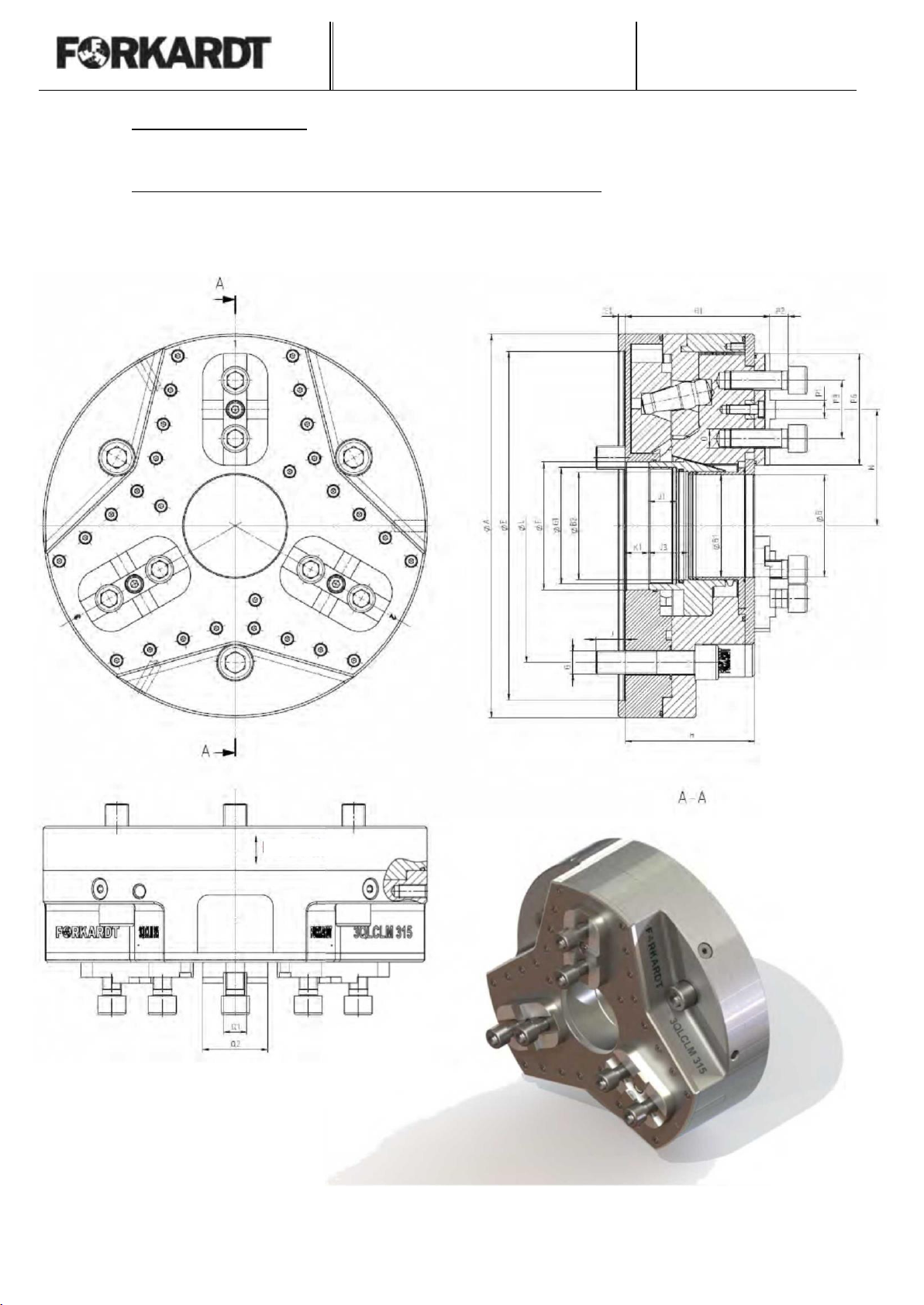
Table of contents
3QLCLM
Edition: 04/2014
12
4.2 Constructive design
4.2.1 Technical data / main dimensions - power chuck type 3QLCLM
3QLC 315-LM-Z11-KDIN
max 4000 U/min
Fmax 60KN
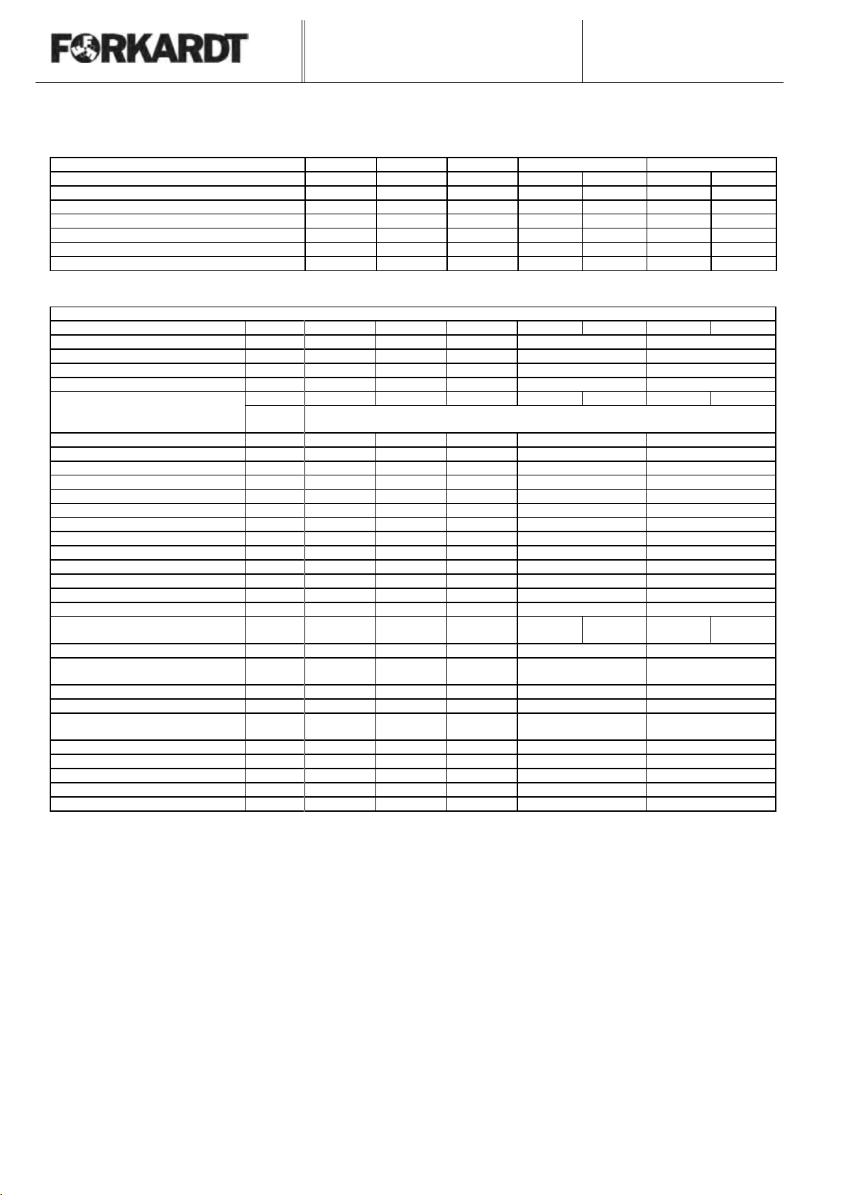
Table of contents
3QLCLM
Edition: 04/2014
13
Technical data / main dimensions
Power chuck Type 3QLCLM
Chuck type 3QLCLM
160-38
200-54
250-72
315-88
400-126
Ident-No.
191203000
191216000
190476000
Max. actuation force - F max
daN
4000
6000
6000
Max. gripping force - Fsp max
daN
7000
9100
12000
Max. speed - n max
min-1
6300
4500
4000
Mass moment of inertia J
kgm2
0.138
0.81
0.81
Moment of inertia GD2
kgm2
0.552
3.24
3.24
Weight G
22.6
38.1
57.3
Dimensions
Spindle connection
ØC
Z5
Z6
Z8
Z8
Z11
Z11
Z15
Chuck size
ØA
175
215
265
330
415
Bore
ØB
38
54
72
88
126
Jaw connection (DIN 6353)
D
KDIN
KDIN
KDIN
KDIN
KDIN
Centering drawbar
ØB2
42
65
77
93
134
Chuck centering
ØE
140
170
220
220
300
300
380
E1
6
Piston bore
ØF
52
76
90
110
150
Fixing screws
G
M12x95
M16x110
M20x90
Thread connection drawbar
G1
M45x2
M68x2
M82x2
M100x2
M140x2
Jacking screw standard sleeve
G2
M4
M5
M6
M6
M6
Chuck height
H
101
101
111
111
141
Chuck height up to jaw support
H1
111
124
124
Mounting depth
H2
5
6
6
Cover height
H3
6
8
8
Thread length mounting bolt
J
20
23.6
30
Thread length actuator
J1
17.5
24
24
Pull length actuator
J2
23.5
34
34
Actuator stroke
K
20
20
20
Actuator position
K1
21.5
20
20
Pitch circle-Ø
Fixing screws
L
104.8
133.4
171.4
171.4
235
235
330
Jaw stroke
4.5
5.4
5.4
5.4
8
Jaw position to the center of
chuck
Nmax.
Nmin.
52
47.5
70
64.6
88
82.6
100
94.6
133
125
Jaw mounting bolt
O
M10
M12
M16
M16
M20
Distance jaw mounting bolt
P1
12.5
15
20
25
35
Minimum distance to jaw mounting
bolt
P2
12
12
16
16
Distance ti jaw mounting bolts
P3
25
30
40
50
70
Length of cross tenon
P4
70
84
96
Jaw width
Q
35
35
45
45
60
Groove width
Q1
16H7
16H7
20H7
20H7
25H7
Feather key width / slot width
Q2
10g6
12g6
16g6
16g6
25g6

Table of contents
3QLCLM
Edition: 04/2014
14
4.2.2 Design of the power chuck
4.2.2.2 Centrifugal force accessories
Chuck-Ø
Centrifugal force
weight
Lever
160
200
191062009
156122010
250
191216009
156584010
315
190476009
156584010
400
CHUCK BODY
JAW COMPLETE
CHUCK COVER
COMPLETE
4.2.2.1 Complete chuck
CENTRIFUGAL FORCE
ACCESSORIES
ACTUATOR COMPLETE
CHUCK
FIXING SCREWS
Lever
Centrifugal force
weight

Table of contents
3QLCLM
Edition: 04/2014
15
Chuck-Ø
Cylinder screws
cover fixing 1
Cylinder screws
cover fixing 2
Cover
O-Ring 1
O-Ring 2
Protective
sleeve
Countersunk
screw
160
-
-
200
701C004320
701C005350
191062005
-
-
191062002
703D004030
250
701D006350
701D006370
191216007
-
711A022030
191216004
703D004030
315
701D006350
701D006370
190476007
711H015037
711A030193
190476004
703D004030
400
Chuck-Ø
O-Ring 3
O-Ring 4
Frame
Locking
screw
Sealing disc
Actuator
O-Ring 5
160
-
200
-
711A020849
191062001
709C212150
171594044
191062003
711A020055
250
711A015050
711A015033
191216001
177821008
191216002
711A030112
315
711A015123
711A015123
190476001
709C212150
171594044
190476002
711A030127
400
4.2.2.3 Chuck body complete
COUNTERSUNK
SCREW
ACTUATOR
O-RING 5
LOCK SCREW
SEALING DISC
CHUCK BODY
O-RING 4
O-RING 3
O-RING 2
O-RING 1
PROTECTIVE SLEEVE
CYLINDER SCREWS
COVER FIXING 0
CYLINDER SCREWS
COVER FIXING 0

Table of contents
3QLCLM
Edition: 04/2014
16
4.2.2.4 Chuck cover complete
Chuck-Ø
Cylinder screws
Chuck cover
O-Ring 1
O-Ring 2
O-Ring 3
160
-
-
200
701B010360
191204001
711A020107
711A015015
711A015014
250
701B010380
191216005
711A030191
711A025075
711A025012
315
701B010380
190476005
711A030198
711A025026
711A025012
400
CYLINDER SCREW
CHUCK COVER
O-RING 3
O-RING 2
O-RING 1
Table of contents
3QLCLM
Edition: 04/2014
17
4.2.2.5 Jaw complete
Chuck-Ø
Cylinder screws
top jaws
Cylinder screw top
jaw
Sealing frame
O-Ring A
Adapter jaw
O-Ring B
Cylinder screw(s)
sliding block
Sliding block
Base jaw
160
200
701B012340
191064002
711A015028
191203001
711A020047
701C005320
191064003
191064001
250
701B016360
701C008360
191216008
711A178051
701B004340
190476010
191216003
315
701B016360
701C008360
190476011
711A020055
190476008
711B178054
701B004340
190476010
190476003
400
CYLINDER SCREW
O-RING A
O-RING B
ADAPTER JAW
CYLINDER SCREWS FOR TOP
JAWS
BASE JAW
SLIDING BLOCK
SEALING FRAME
CYLINDER SCREWS FOR FIXING THE
ADAPTER JAW

Table of contents
3QLCLM
Edition: 04/2014
18
4.3 Function of the power chuck
4.3.1 General information:
The power chuck is actuated through a standard hydraulic cylinder with monitoring of chucking stroke, by
using machine hydraulics or a separately provides hydraulic unit.
Depending on the type of work pieces to be machined, the following are used:
Partly open chuck
a hydraulic actuating cylinder
e.g. Type OKRJ...
or
Open chuck
a hydraulic hollow cylinder
e.g. Type OKHJ...
.
In some cases, hydraulic cylinder of
type PZRAJ or PZHAMJ is used.
The power chuck, fixed to the spindle head of a lathe, is actuated axially through a hydraulic clamping
cylinder and has the function to generate a gripping force to hold the work piece to be clamped through
the axial force generated by the clamping cylinder.
The pressure at the clamping cylinder must be adjusted such that the max.
permissible actuation force of the power chuck is not exceeded.
The axial actuation force of the clamping cylinder, which is spread on the actuator surface through
pressure, is transferred to the corresponding wedge guides of the master jaw through the wedge surfaces
laid out in the chuck actuator and these wedge guides wedge into each other during the clamping process.
The corresponding gripping force builds up radially on the work piece through the top jaws.
Clamping force at the chuck actuator causes jaw stroke to the inside (outside clamping). Compressive
force at the chuck actuator causes jaw stroke to the outside (inside clamping of hollow work pieces). The
power chuck type 3QLCLM is equally suitable for both clamping devices.
The monitoring of the clamping path is done through radially arranged limit switch on the clamping
cylinder.
Partly open chuck
Open chuck
Table of contents
3QLCLM
Edition: 04/2014
19
If the top jaw is adjusted to a specific clamping diameter, the jaw mounting bolts must be loosened
through two rotations with the Allen wrench (in accordance with 911) and the top jaw must be pushed
into the corresponding clamping diameter with the sliding blocks and screws.
If there is a change of top jaws from outer to inner clamping,
watch out for change in the direction of movement of the top jaws,
or if the top jaws are changed for example from hard top jaw type HB for roughing operation to soft top
jaw type WBL for finishing, then the jaw mounting bolts must be loosened through two rotations (with
Allen wrench) and the top jaw must be removed completely from the master jaw.
Clean any chips or dirt from the chuck bore and master jaw before removing the top
jaw from the master jaw!
If the processing of the clamped work piece is interrupted for many hours, the power chuck and/or the
clamping cylinder must be actuated again.
4.3.2 Centrifugal force compensation
Each master jaw is assigned to a counterweight through a reversing lever. When the chuck is rotated, it
uses its centrifugal force to balance the centrifugal force of the base and top jaw, which otherwise may
result in significant loss of gripping force. This simple, robust and direct centrifugal force compensation
system ensures high gripping force of the 3QLCLM power chuck in the entire speed range on the one
hand and allows selective processing with reduced gripping force on the other hand even at maximum
finishing speeds.
4.3.3 Lubrication
The movement of the centrifugal weight in the rear part of the chuck is used to supply lubricant to all
sliding surfaces during each chucking stroke. The excess lubricant inside the chuck is centrifuged to
the required points through the rotation of the chuck and is available again for the next chucking stroke.
When compared to the traditional chuck guides, the 3QLCLM type power chucks can use lubricants
with low viscosity, which can reach the sliding surfaces in a better way due to centrifugal capability.
This improves the reliability of the lubrication function and makes cleaning and maintenance of the
3QLCLM power chuck much easier.
4.3.4 Sealing of the power chuck
Type 3QLCLM power chucks maintenance-free thanks to their sealing and are sealed against entry of
lubricants and functional disruptions caused by the entry of coolants, dirt and chips.

Table of contents
3QLCLM
Edition: 04/2014
20
4.4 Clamping jaw
4.4.1 General information
The power chuck is a connecting element between the lathe and the work piece to be processed. The
power produced by the lathe is transmitted to the spindle nose by the power chuck and
to the transfer point between power chuck and work piece by the positive driving of the
closed chuck jaws.
Wide chuck jaws must be avoided
because they come to stop at the work
piece unevenly and cause radial
run-outs.
The power chuck is a connecting element between the lathe and the work piece to be processed. The
power produced by the lathe is transmitted to the spindle nose (by the power chuck) and
to the transfer point between power chuck and work piece (by the positive driving of the
closed chuck jaws). Chuck jaws are the radially moving elements of the power chuck, which hold the
work piece during machining. The chuck jaws consist of the master jaw (the connecting
link to the power-providing part of the power chuck) and the top jaw which is positively attached
(by serrations) to the master jaw and can thus be exactly positioned. The chuck jaws
have to be changed to suit the type of machining or the differences in size and shape of the work
pieces. The chuck jaws must be trained separately for optimal use and to prevent run-outs.
For the type QLCLM power chuck, the top jaw may have different holders for fixing to the
master jaw depending on the design:
•Cross tenon
•Different quick change systems
4.4.2 Safety instructions for top jaws
•Recalculate the strength of self-manufactured top jaws using the gripping force.
•Only use ORIGINAL mounting bolts for fixing the top jaws with due consideration of the
prescribed quality! (Cross tenon)
•Set the speed limiting device on the lathe to the permissible speed determined for the special
top jaws, as otherwise the centrifugal forces occurring at the jaws at higher
speeds will reduce the gripping force to such an extent that the work pieces will
no longer be securely held!
Comprehensive jaws come to stop
unevenly at the work piece on one
side and cause radial run-outs.
Power chuck center = workpiece
center or center of rotation
Center of eccentric chuck
diameter


