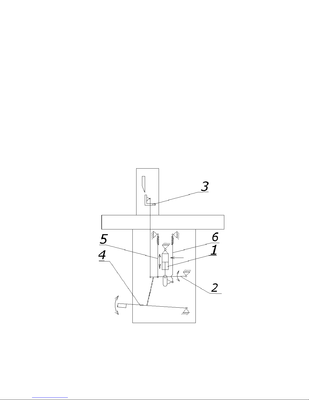
8
– acting cylinder (actuator) 1 through the levers 2, pulls clamping beam 3 down.
Clamping beam 3 is shifted in the slideways (not stated on the drawing) , that
guarantees its parallelism to the cutting line.
Lowering down the clamp bar 3 is possible also by pressing foot pedal 4. Pushing the
pedal 4 moves the bar 5 into the lower position. Return of the clamping bar 3 is
permitted by the spring 5. Spring 6 causes the return of cylinder 1 into its start position.
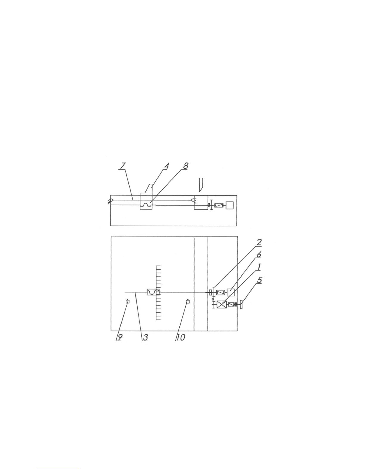
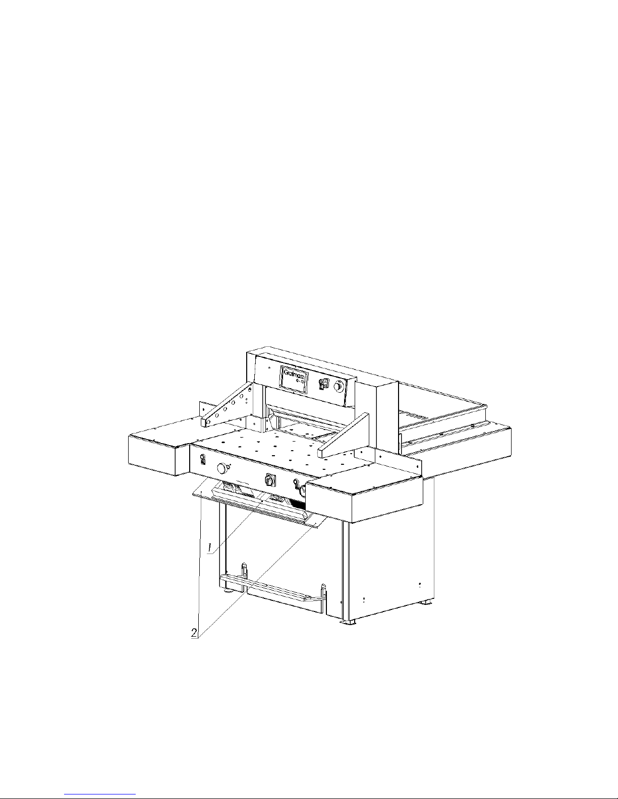
2.3.3 Back gauge mechanism
Drawing 6. Kinematic diagram for backgauge mechanism.
Electric motor 1 drives the feed screw through the belt transmission 2, through the
nut forcing the movement of the base motion 8 .
The base 8, bolted together with the backgauge bar 4, is guided on the guiding shaft 7.
The limit switches 9, 10 cause the backgauge bar 4 to stop in its extreme positions.
An accurate setting of the backgauge bar enables knob 5. The pulse- rotary converter