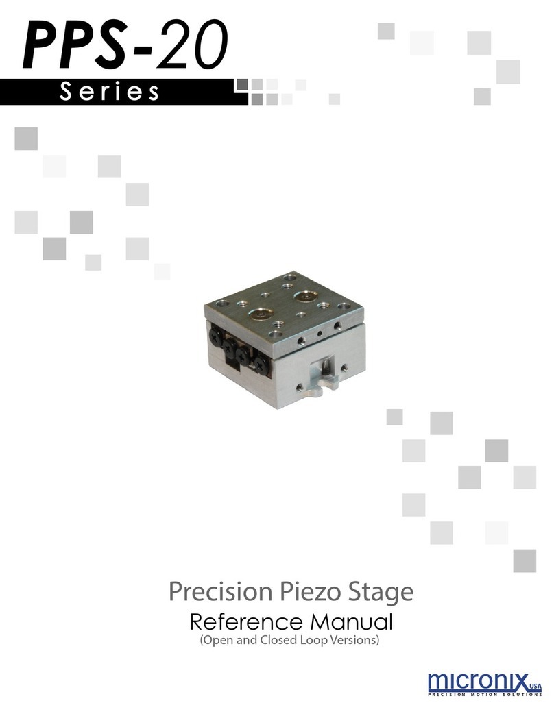
FormFactor MS Series User manual

-~
ARTISAN
®
~I
TECHNOLOGY
GROUP
Your definitive source
for
quality
pre-owned
equipment.
Artisan Technology
Group
Full-service,
independent
repair
center
with
experienced
engineers
and
technicians
on staff.
We
buy
your
excess,
underutilized,
and
idle
equipment
along
with
credit
for
buybacks
and
trade-ins
.
Custom
engineering
so
your
equipment
works
exactly as
you
specify.
•
Critical
and
expedited
services
•
Leasing
/
Rentals/
Demos
• In
stock/
Ready-to-ship
•
!TAR-certified
secure
asset
solutions
Expert
team
ITrust
guarantee
I
100%
satisfaction
All
tr
ademarks,
br
a
nd
names, a
nd
br
a
nd
s a
pp
earing here
in
are
th
e property of
th
e
ir
r
es
pecti
ve
ow
ner
s.
Visit our website - Click HERE


© Copyright 2018 FormFactor, Inc. All rights reserved. No part of this document may be reproduced, transmitted or displayed in any form or
by any means except as duly authorized by FormFactor, Inc. FormFactor and the FormFactor logo are trademarks of FormFactor, Inc. All
other trademarks are the property of their respective owners.
Important Notice
While the information contained herein is believed to be accurate as of the date hereof, no express or implied representations or warranties
are made with respect to its accuracy or completeness. FormFactor, Inc., and its subsidiaries disclaim liability for any inaccuracies or
omissions. All information is subject to change without notice.
Users are required to read and follow carefully all safety, compliance and use instructions. Users assume all loss and liability arising from the
use of products in any manner not expressly authorized. The conditions and methods of use of products and information referred to herein
are the entire responsibility of the user and, to the maximum extent permitted by applicable law, FormFactor, Inc., and its subsidiaries shall
not be liable for any damages, losses, costs or expenses arising out of, or related to, the use thereof.
No license, express or implied, by estoppel or otherwise, under any intellectual property right is granted in connection herewith. Users shall
take all actions required to avoid intellectual property infringement.

Contents • i
Contents
Contents .......................................................................................................................................i
Before You Begin ........................................................................................................................iii
About This Guide ........................................................................................................................... iii
Notational Conventions................................................................................................................. iii
For More Information.................................................................................................................... iii
Chapter 1: Overview .....................................................................................................................1
Micropositioner Overview.............................................................................................................. 1
Features .................................................................................................................................1
Requirements ........................................................................................................................1
Safety .....................................................................................................................................1
Returning a Micropositioner for Service ........................................................................................ 1
RMA Number .........................................................................................................................1
Repacking ..............................................................................................................................2
Chapter 2: ERJ-02 Joystick .............................................................................................................3
Controls .......................................................................................................................................... 3
Operation ....................................................................................................................................... 4
Initializing Channels ...............................................................................................................4
Activating a Channel ..............................................................................................................4
Selecting Axis (X, Y, Z, Theta) .................................................................................................5
Set Contact Location ..............................................................................................................5
Set Separate Location ............................................................................................................5
Set Increment Distance .........................................................................................................6
Move in Increments (Die Stepping) .......................................................................................6
Chapter 3: MAC-Series Mounts .....................................................................................................7
MAC-02 Magnetic-Mount............................................................................................................... 7
MAC-02 Mount Dimensions ..................................................................................................8
MAC-05 Bolt-Down Mount............................................................................................................. 9
MAC-05 Mount Dimensions ................................................................................................10
MAC-22 Vacuum Mount............................................................................................................... 10
MAC-22 Vacuum Base Dimensions ......................................................................................11
Planarizing .................................................................................................................................... 11
Planarizing the Y-Axis ...........................................................................................................12
Planarizing the X-Axis ..........................................................................................................13
Chapter 4: Slide Mount for Summit 12K ......................................................................................15
Installing the Slide Mount ............................................................................................................ 15
Positioner Configurations ....................................................................................................15
Rail and Single Positioner ..........................................................................................15

ii • MS Series Micropositioners
Rail and Double Positioners ...................................................................................... 15
Installing the Rails ............................................................................................................... 16
North-South Positioner ............................................................................................. 17
East-West Positioner ................................................................................................. 17
Initializing the Positioners............................................................................................................ 17
Appendix A: Topic A ................................................................................................................... 19
Micropositioner Specifications .................................................................................................... 19
Micropositioner Dimensions........................................................................................................ 19
Axis Directions.............................................................................................................................. 20
Connector Pin Assignments ......................................................................................................... 20
Right-Hand MS1 and MS2 Pin Assignments ........................................................................ 20
Left-Hand MS1 and MS2 Pin Assignments .......................................................................... 21
Index ......................................................................................................................................... 23

Before You Begin • iii
Before You Begin
About This Guide
Welcome to the MS Series Micropositioners User Guide. This guide contains information
about micropositioner mounts and planarization.
Notational Conventions
This manual uses the following conventions:
NOTE
Note is used to indicate important information about the product that is not hazard related.
CAUTION
Caution is used to indicate the presence of a hazard which will or can cause minor personal
injury or property damage if the warning is ignored.
WARNING
Warning is used to indicate the presence of a hazard which can cause substantial personal
injury or property damage if the warning is ignored.
DANGER
Danger is used to indicate the presence of a hazard which will cause severe personal injury,
death or substantial property damage if the warning is ignored.
For More Information
More information may be available from these sources:
• Your probe station user guide
• Release Notes
• FormFactor’s website at www.formfactor.com.
• If you purchased your FormFactor product from a third-party vendor, you can contact that
vendor for service and support.
i
!
!
STOP

Overview • 1
Chapter
1Overview
Micropositioner Overview
Features
• Three axes of linear motion are available, with either 25.4 mm or 50.8 mm (1-inch or
2-inches) of travel.
• High-resolution, true linear motion provides ultra precise probe-tip placement (0.1 micron
step size).
• Small positioner size allows up to (6) micropositioners to be fitted to a 203 mm (8-inch)
station.
• Positioners can be operated manually, or through the use of the ERJ-02 joystick or the
probe system software.
• Both right- and left-handed models are available.
• Positioners are D.C.-, active-, coaxial-, or triaxial-probe compatible for capturing low level
and high frequency measurements.
• Mounts for most probes, grippers, and cutters are available.
• An an IEEE interface is also available.
Requirements
MS-Series micropositioners require the following:
• An ECX-56 expansion box (or equivalent)
• An ECA-53 expansion drive card (one card is required by each micropositioner)
Safety
The information in this guide facilitates the safe and effective operation of equipment. Any
deviation from the recommended procedures, modification to or use of the equipment for a
purpose for which it is not designed may create a hazardous operating situation. FormFactor,
Inc., disclaims any responsibility for consequences resulting from any such deviation,
modification, or application.
Returning a Micropositioner for Service
RMA Number
Before shipping a probe station to FormFactor, obtain a Return Material Authorization number
(RMA #). Contact the nearest FormFactor sales office, or in the U.S. call customer service at
(800) 550-3279 or (503) 601-1000.

2 • MS Series Micropositioners
Write the following information on a tag and attach it to the probe station:
• Owner's name and address
• RMA number
• Probe station model number
• Probe station serial number (back left of probe station)
• Description of the service required or failure indications
Repacking
To retain the validity of the warranty, always use the original packing materials. Contact a
FormFactor representative for replacement shipping materials or hardware.

ERJ-02 Joystick • 3
Chapter
2ERJ-02 Joystick
Controls
The ERJ-02 controls up to four channels in x, y and z (plus theta, if DUT is used).
CAUTION
Be sure that the locking sliders are in the positions shown above. If positioned incorrectly, the
z-knob will fall to one side, causing the stage to drift. This movement can cause the probes to
crash.
Knob with theta
Be sure this lock slider is
in its rightmost position.
Cycle Z button
Be sure this lock slider
is in its down position.
!
Knob with Theta The knob is used for x-, y-, z-, and theta-motion.
Channel Select Button The channel select button is used to change the channel that the knob controls. The channel
LED indicators indicate the channel that is currently active.
Channel LED Indicators The channel LED indicators indicate the channel that is controlled by the knob.
Set Button The set button is used in conjunction with other buttons for “setting” certain parameters of
stage motion.
Locking Sliders The locking sliders must remain in the locked position. If positioned incorrectly, the z-knob
will fall to one side, causing the stage to drift. This movement can cause the probes to crash.
Cycle Z Button This button selects the axis that is controlled by the knob.
Con and Sep The Con(tact) and Sep(arate) buttons are used for moving the chuck to the contact and the
separate positions.
Channel indicators Four channel LED indicators indicate the currently active channel. Pressing the Channel
Select button will cause the channel to change. If the channel indicator blinks, the theta
stage is active. Twisting the knob will cause the DUT to rotate.
Channel selector LED If the channel selector button blinks, the z-axis is active. Twisting the knob will cause the
channel to move in z.

4 • MS Series Micropositioners
Operation
Initializing Channels
Initializing a channel causes the prober to find the center of travel for that channel. The center
then becomes the home position.
CAUTION
Before initializing a channel, ensure that the probes and wafer will not crash.
If either the Con or the Sep buttons are blinking quickly, at least one channel has not been
initialized.
Clear the fast blinking before using the probing station.
1. Press the channel select key until the channel to be initialized is active (Channel LED is
on).
2. Press and hold the set key, then press the channel select button. The channel will begin
initializing. Release both buttons.
NOTE
To interrupt the initialization process, simply move the joystick. Doing so leaves the channel in
an uninitialized state.
3. When the initialization is finished, all four channel LED indicators will blink for about 1/4 of
a second.
Activating a Channel
After all channels have been initialized, the channel select button can be used to change the
channel currently controlled by the knob. The following table shows the LED indicating each
channel.
NOTE
If either the channel select LED or the channel LED is blinking, the knob is in z- or theta-mode.
Pressing the channel select button will have no effect. Press the Cycle (z) button until no LED
indicators are blinking. Then press the channel select button to change the channel.
Con and Sep LED If the Con LED indicator is turned on, the z-axis is at the contact position. If the Sep LED
indicator is turned on, the z-axis is at or beyond the separate position. If neither of the Con or
Sep LED indicators are on, it means the z-axis is somewhere in between the contact and
separate positions. If the Con or Sep LED indicators are blinking quickly, at least one
channel has not yet been initialized.
Set LED If the Set LED indicator is blinking, the set mode is active. The next button pressed while in
set mode will have an effect on the motion parameters for the joystick. For example,
pressing the Con button will load the current z-position as the contact position. Pressing the
Sep button will load the current z-position as the separate position.
!
i
LED Channel
1 DUT, or Scope, or Probe 1
2 Scope
3 Probe1
4 Probe2
i

ERJ-02 Joystick • 5
Selecting Axis (X, Y, Z, Theta)
After a channel has been selected, the Cycle (z) button on top of the knob can be used to
select the axis currently controlled by the knob.
• When a channel is first selected and no LED indicators are blinking, the knob controls the
x/y axis. Moving the knob will cause the x/y stage to move. The more the knob is
deflected, the faster the stage will move.
• Pressing the Cycle (z) button once will cause the channel select LED indicator to blink.
This means that the knob controls z-axis. Twisting the knob causes the z-axis to move.
The more the knob is twisted, the faster the stage will move. Pushing the knob in x or y will
have no effect.
NOTE
The z-axis has protections built in so it will not move beyond the contact position. If the z-axis
reaches the contact position, it will stop moving and the channel LED indicators will blink
simultaneously. This is to protect the probes and wafer from being damaged. Releasing the
knob will make the channel LED indicators stop blinking. To move the z-axis beyond the
contact position, the Set mode must be activated.
• If the current channel is the DUT, pressing the Cycle (z) button again will cause the
Channel LED to blink. This means the knob controls theta rotation. Twisting the knob
causes the theta stage to rotate. Pushing the knob is x or y will also cause the x/y stage to
move.
• Pressing the Cycle (z) button again will set the mode back to x/y (no LED indicators
blinking).
Set Contact Location
The contact location is the stored z-position for a channel that is moved to make the probes
contact the wafer. Set the contact position for the DUT before the probes.
1. Press the channel select key to select the channel to be set.
2. Press the Cycle (z) button to activate the z-axis. The channel select button will begin
blinking.
3. Press the Set key. The set key will begin blinking, indicating the set mode is active.
4. At this point, the normal protections for the z-axis are disabled (i.e., the z-axis will be
allowed to move its full range of motion).
5. Twist the knob to move the z-axis to the desired contact position.
6. Press the Con button to store the current z-position as the contact position and deactivate
the set mode.
7. Press the Sep button. The z-axis will move to the separate position.
8. Press the Con button to return the z-axis to the contact position that was just loaded.
CAUTION
To avoid the risk of severe damage to the wafer and probes, set the DUT contact before using
the probes.
Set Separate Location
The separate location is the stored z-position for a channel that is to be moved to take the
probes out of contact with the wafer. The z-axis will move to the separate position before any
x/y or theta moves occur.
i
!

6 • MS Series Micropositioners
The default separate position (100 microns above contact) is adequate for most applications.
The separate position is relative to the contact position, so loading a new contact position will
change the separate position as well (it’s usually not necessary to set the separate position).
1. Press the channel select key to select the channel to be set.
2. Press the Cycle (z) button to activate the z-axis. The channel select button will begin
blinking.
3. Twist the knob to move the z-axis to the desired separate position. The separate position
must always be further away from the wafer than the contact position.
4. Press the Set button. The set button will begin blinking, indicating the set mode is active.
Note while the set mode is active, the protections for driving the z-axis into the wafer are
temporarily disabled.
5. Press the Sep button to store the current z-position as the separate position and
deactivate the set mode.
6. Press the Con button. The z-axis will move the contact position.
7. Press the Sep button to return the z-axis to the separate position that was just loaded.
Set Increment Distance
Increment moves are used to move a whole die location. Setting the increment involves
loading the same corner on two adjacent die so that the prober can calculate the distance
between rows and columns.
1. Select the DUT or Scope channel.
2. Move to a corner of a die.
3. Press the Set key to activate the set mode. The set button will blink.
4. Press the Cycle (z) button (top of knob) to save the current position in x and y. The set
button will blink faster.
5. Move to the same corner of the next die. Move a row and column (kitty-corner).
6. Press the Cycle (z) button again. The distance between the two corners is computed and
stored. The Set button will stop blinking.
Move in Increments (Die Stepping)
Die stepping is used to move the stage one complete row or column. This requires the die size
to be loaded first.
1. Press and hold the Set button.
2. Deflect the knob. The amount of deflection does not matter as the stage will move either
one row or one column.

MAC-Series Mounts • 7
Chapter
3MAC-Series Mounts
MAC-02 Magnetic-Mount
NOTE
Magnetic-mount positioners are not recommended for microwave testing.
i

MAC-Series Mounts • 9
MAC-05 Bolt-Down Mount
CAUTION
Make sure that the mounting screws are tight.
Three (3) 6-32 x .88-inch mounting screws are used to fasten the MAC-05 mount to the
micropositioner. Three (3) adjustment bolts hold the mounting screws and are used for fine
planarization adjustments.
!
Mounting screw
Adjustment bolt
Platen

10 • MS Series Micropositioners
MAC-05 Mount Dimensions
MAC-22 Vacuum Mount
Three (3) 6-32 x .50-inch mounting/adjustment screws are used to fasten the MAC-22 mount
to the micropositioner. These screws are also used to planarize the positioner. The MAC-22
base is attached to the positioner as shown below.
4.0
1.49
1.49

MAC-Series Mounts • 11
MAC-22 Vacuum Base Dimensions
Planarizing
CAUTION
The probe station must be planarized before attempting positioner planarization. Take care
when loosening the mounting/planarization screws for the x-and y-axis. Do not loosen the
screws to the point that the mount is at risk of falling from the micropositioner.
NOTE
Use the highest magnification (up to 500X) when planarizing.
1.020
7.524
2.252
4.500
2.124
4.000
1.19
4.500
!
i
Table of contents


