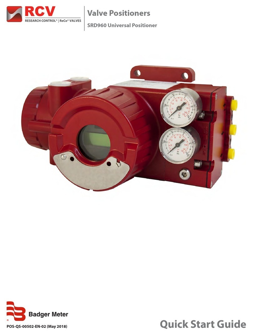
Badger Meter RCV SRI990 User manual

Valve Positioners
SRI990 Analog Positioner
POS-QS-00007-EN-02 (May 2018) Quick Start Guide

Valve Positioners, SRI990 Analog Positioner
Page ii July 2013POS-QS-00007-EN-02

CONTENTS
Mounting to actuators . . . . . . . . . . . . . . . . . . . . . . . . . . . . . . . . . . . . . . . . . . . . . . . . . . . . . . . . . . . . . . . . . . . 5
Mounting to Linear Actuators. . . . . . . . . . . . . . . . . . . . . . . . . . . . . . . . . . . . . . . . . . . . . . . . . . . . . . . . . . . .5
Mounting to Rotary Actuators . . . . . . . . . . . . . . . . . . . . . . . . . . . . . . . . . . . . . . . . . . . . . . . . . . . . . . . . . . . 6
Pneumatic Connections . . . . . . . . . . . . . . . . . . . . . . . . . . . . . . . . . . . . . . . . . . . . . . . . . . . . . . . . . . . . . . . . . . 8
Electrical connections . . . . . . . . . . . . . . . . . . . . . . . . . . . . . . . . . . . . . . . . . . . . . . . . . . . . . . . . . . . . . . . . . . . 8
START UP (setting by means of local switches and potentiometers) . . . . . . . . . . . . . . . . . . . . . . . . . . . . . . . . . . . . . . 9
Initial Setting . . . . . . . . . . . . . . . . . . . . . . . . . . . . . . . . . . . . . . . . . . . . . . . . . . . . . . . . . . . . . . . . . . . . . . 9
Conguration Direction of Rotation of Feedback Shaft. . . . . . . . . . . . . . . . . . . . . . . . . . . . . . . . . . . . . . . . . . . .9
Setting of Zero, Span and Gain . . . . . . . . . . . . . . . . . . . . . . . . . . . . . . . . . . . . . . . . . . . . . . . . . . . . . . . . . . 10
Setting and Start Up of position transmitter 4-20mA . . . . . . . . . . . . . . . . . . . . . . . . . . . . . . . . . . . . . . . . . . . . . . .10
Adjusting the Start of the Measuring Range (4mA) . . . . . . . . . . . . . . . . . . . . . . . . . . . . . . . . . . . . . . . . . . . . . 10
Adjusting the End of the Measuring Range (20mA) . . . . . . . . . . . . . . . . . . . . . . . . . . . . . . . . . . . . . . . . . . . . . 10
Quick Start Guide
Page iiiJuly 2013 POS-QS-00007-EN-02

Valve Positioners, SRI990 Analog Positioner
Page iv July 2013POS-QS-00007-EN-02

Use this document as a guide for quick startup. For more detailed information, see the positioner’s User Manual and Product
Data Sheet, available on our website at www.badgermeter.com.
MOUNTING TO ACTUATORS
During operation the flat side of the spindle 9 on the back of the positioner must always point towards the arrow 26. The
working angle around this position is ± 45°.
Figure 1: Actuator orientation
Mounting to Linear Actuators
gnitnuomRUMANgnitnuomtceriDgnitnuomRUMAN
- left hand
- - right hand -
Figure 2: Mounting to linear actuators
Mounting to actuators
Page 5July 2013 POS-QS-00007-EN-02

Feedback Lever for Linear Actuators
The carrier bolt Bis in the slot of the feedback lever Aand the compensating spring Ftouches the carrier bolt.
Carrier bolt B:
1 threaded sleeve
2 Stud
3 coupling piece
Figure 3: Feedback lever and carrier bolt
Mounting to Rotary Actuators
• Do not tighten grub screw 4against the thread of spindle 9.
• When in use, the flat side of the spindle 9 must move 0 ↔100% in front of the arrow 26.
• When the product temperature rises, the drive shaft 1increases in length. Therefore, the rotary adapter 3must be
mounted so there is approximately 1 mm (0.04 in.) of clearance between the drive shaft 1and the rotary adapter 3. The
clearance is achieved by placing an appropriate number of washers 5on the feedback spindle 9before attaching the
rotary adapter. Two washers should result in a clearance of 1 mm.
Mounting to actuators
Page 6 July 2013POS-QS-00007-EN-02

Actuator, left turnin
gA
ctuator, right turning
Figure 4: Actuators
Mounting to actuators
Page 7July 2013 POS-QS-00007-EN-02

PNEUMATIC CONNECTIONS
Air supply: 1.4…6 bar (but not more than the maximum pressure of the actuator), free of oil, dust and water.
Single acting, direct mounting Single acting Double acting
s air supply y1, y2 pneumatic outputs (--) closed
Figure 5: Pneumatic connections
ELECTRICAL CONNECTIONS
Observe the safety requirements listed in the user manual.
3.3 Limit switch
SRI990-xxxT
or
U
Two-wire proximity sensors,
Acc. to DIN 19234 or NAMUR
Supply voltage DC 8 V
SRI990-xxxV
Warning: For connection of micr
o
switches please refer to MI
(Master
Instruction) and respect the safety
requirements described in document
EX EVE0001.
Switching amplifier with
intrinsically safe control circuit
Switching amplifier with
intrinsically safe control circuit
3.1Setpoint
Input 4 to 20 mA
3.2Position
feedback 4-20 mA
(SRI990-xxQ)
Analog output 4 to 20 mA,
Two-wire system,
Supply voltage DC 8 to 48 V*
* For intrinsically safe circuits, please refer to certificate / data label for max. operating voltages.
Pneumatic Connections
Page 8 July 2013POS-QS-00007-EN-02

STARTUP SETTING BY MEANS OF LOCAL SWITCHES AND
POTENTIOMETERS
Initial Setting
Figure 6: Initial setting
After mounting the positioner on the actuator, air and electrical input
connected, proceed as follow.
Put all switches in position I. This is the setting for input signal
“4 to 20 mA” and“Left mounted”(counter clockwise rotation).
Conguration Direction of Rotation of Feedback Shaft
Defined as direction of rotation of feedback shaft from the start to the end position, looking at the positioner from the front.
Switch 1+2 to“R” if necessary.
R= right turn (clockwise) L= left turn (counter cw)
Figure 7: Configuring direction of rotation
STARTUP (setting by means of local switches and potentiometers)
Page 9July 2013 POS-QS-00007-EN-02

Setting of Zero, Span and Gain
Figure 8: Setting zero, span and gain
1. Apply 4 mA to Input.
2. Turn potentiometer P3 for zero point (ZERO) until actuator just
begins to move from its end position.
Rotate P3 to the right: zero point is increased.
Rotate P3 to the left: zero point is reduced.
3. Apply 20 mA to Input
4. Turn potentiometer P2 for span (S) until actuator exactly reaches its
end position.
Rotate P2 to the right: span is increased.
Rotate P2 to the left: span is reduced.
5. The loop amplication of the positioner is set via potentiometer P4.
Trim the gain so that the actuator will not swing at constant given
input value.
6. Re-check zero and span settings.
SETTING AND STARTUP OF POSITION TRANSMITTER 420MA
Verify the electronic connection of the position transmitter. Both LED’s are then light up.
Adjusting the Start of the Measuring Range (4 mA)
7. Move the actuator to the starting position.
8. Press push-button S1 "Cong Output 4mA“ longer than 2 seconds. During this time, LED 1lights up. After 2seconds, both
LED’s light up again and the value for 4 mA is stored.
Adjusting the End of the Measuring Range (20mA)
9. Move the actuator to the end position.
10. Press push-button S2 "Cong Output 20 mA“ longer than 2 seconds. During this time, LED 2lights up. After 2seconds,
both LED’s light up again and the value for 20 mA is stored.
Figure 9: Adjusting measuring range
Setting and StartUp of position transmitter 4-20mA
Page 10 July 2013POS-QS-00007-EN-02

INTENTIONAL BLANK PAGE
Quick Start Guide
Page 11July 2013 POS-QS-00007-EN-02

www.badgermeter.com
Research Control is a registered trademark of Badger Meter, Inc. Other trademarks appearing in this document are the property of their respective entities. Due to continuous
research, product improvements and enhancements, Badger Meter reserves the right to change product or system specications without notice, except to the extent an
outstanding contractual obligation exists. © 2018 Badger Meter, Inc. All rights reserved.
Control. Manage. Optimize.
The Americas | Badger Meter | 4545 West Brown Deer Rd | PO Box 245036 | Milwaukee, WI 53224-9536 | 800-876-3837 | 414-355-0400
México | Badger Meter de las Americas, S.A. de C.V. | Pedro Luis Ogazón N°32 | Esq. Angelina N°24 | Colonia Guadalupe Inn | CP 01050 | México, DF | México | +52-55-5662-0882
Europe, Eastern Europe Branch Oce (for Poland, Latvia, Lithuania, Estonia, Ukraine, Belarus) | Badger Meter Europe | ul. Korfantego 6 | 44-193 Knurów | Poland | +48-32-236-8787
Europe, Middle East and Africa | Badger Meter Europa GmbH | Nurtinger Str 76 | 72639 Neuen | Germany | +49-7025-9208-0
Europe, Middle East Branch Oce | Badger Meter Europe | PO Box 341442 | Dubai Silicon Oasis, Head Quarter Building, Wing C, Oce #C209 | Dubai / UAE | +971-4-371 2503
Slovakia | Badger Meter Slovakia s.r.o. | Racianska 109/B | 831 02 Bratislava, Slovakia | +421-2-44 63 83 01
Asia Pacic | Badger Meter | 80 Marine Parade Rd | 21-06 Parkway Parade | Singapore 449269 | +65-63464836
China | Badger Meter | 7-1202 | 99 Hangzhong Road | Minhang District | Shanghai | China 201101 | +86-21-5763 5412
Switzerland | Badger Meter Swiss AG | Mittelholzerstrasse 8 | 3006 Bern | Switzerland | +41-31-932 01 11
Valve Positioners, SRI990 Analog Positioner
This manual suits for next models
1
Table of contents
Other Badger Meter Valve Positioner manuals