Forms + Surfaces levele User manual
T 1.800.451.0410 | F 412.781.7840 | www.forms-surfaces.com
page 1 of 7 | 10-16-17
LEVELe®ELEVATOR INTERIORS WITH LIGHTPLANE
INSTALLATION INSTRUCTIONS
© 2017 Forms+Surfaces® | All dimensions are nominal. Specifications and pricing subject to change without notice. For the most current version of this document, please refer to our website at www.forms-surfaces.com.
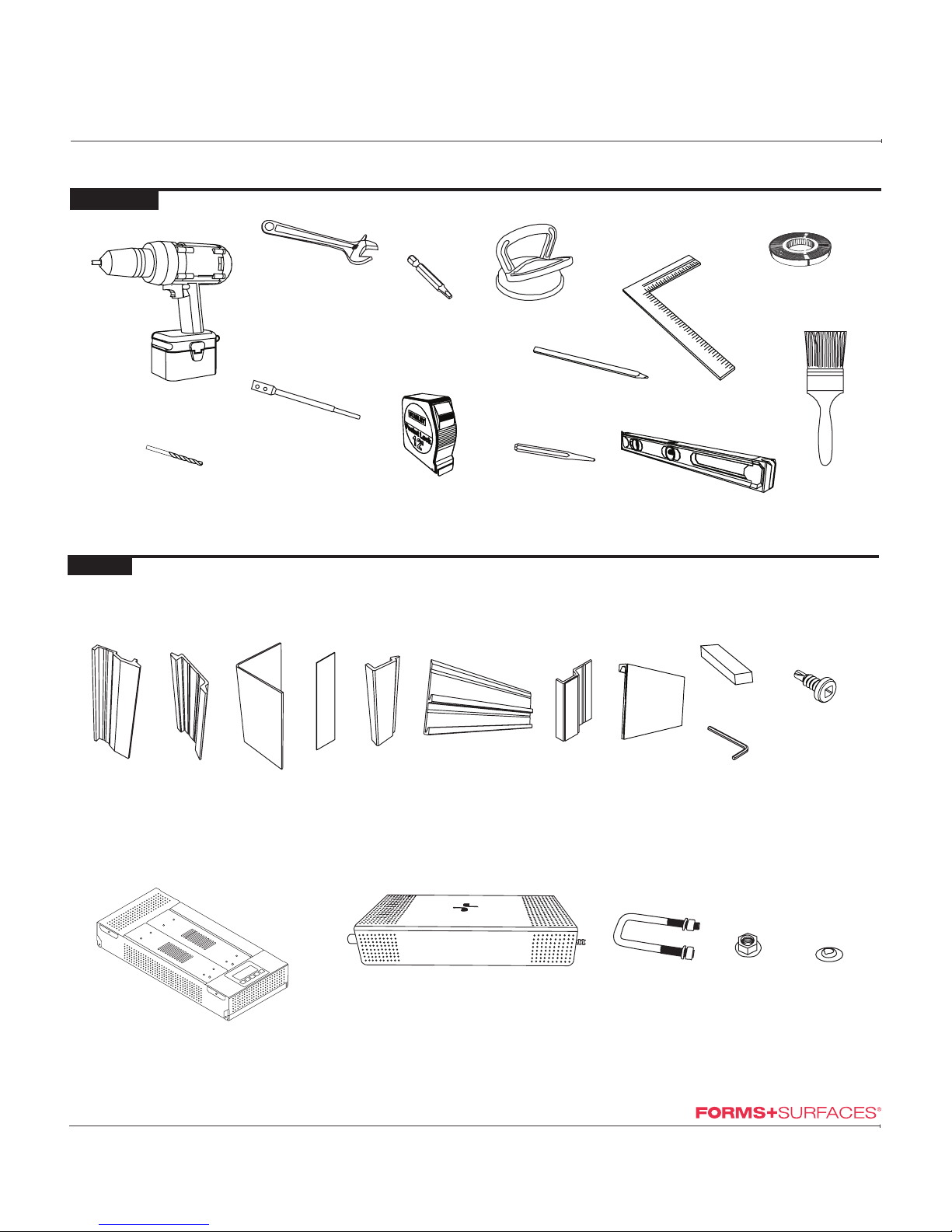
TOOLS NEEDED
IMPACT
DRILL
SQUARE MASKING TAPE
PENCIL
LEVEL
TAPE
MEASURE
CRESCENT WRENCH
3/8" DRILL
BIT
CENTER
PUNCH
BRUSH
SUCTION
CUP(S)
DRILL BIT
EXTENDER
#8-18 SQUARE / PHILIPS
COMBO DRIVE BIT
U-BOLT LOCKING DISC
3/8" - 16
FLANGE NUT
INCLUDED
CEILING COMPONENTS
STANDARD LEVELe COMPONENTS
LIGHTPLANE COMPONENTS
LIGHTPLANE PANEL
POWER BOX
ALLEN
KEY
MOUNTING
EXTRUSION
PANEL
CLIP CORNER
REVEAL
FRONT
REVEAL
COVER
EXTRUSION
BASE CLEAT BASE
SUPPORT
BASE
FACING
SPACER
CEILING POWER BOX
#8 x 1/2"
SELF TAPPING SCREW
W/ #2 SQUARED
DRIVE HEAD
T 1.800.451.0410 | F 412.781.7840 | www.forms-surfaces.com
page 2 of 7 | 10-16-17
LEVELe®ELEVATOR INTERIORS WITH LIGHTPLANE
INSTALLATION INSTRUCTIONS
© 2017 Forms+Surfaces® | All dimensions are nominal. Specifications and pricing subject to change without notice. For the most current version of this document, please refer to our website at www.forms-surfaces.com.
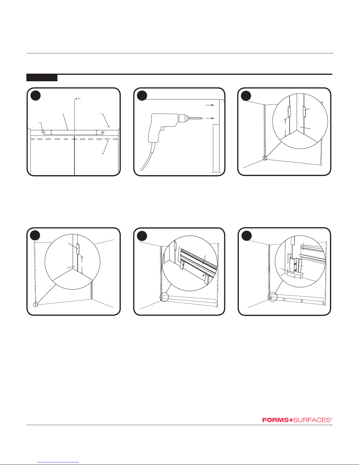
Install (2) Front Reveals.
• Position Front Reveals and install using
factory installed VHB tape.
Note: Detail is inside view of front corner.
45
Install (2) Corner Reveals.
• Position Corner Reveals and hold them in
place with masking tape.
• Cover no more than 1/8" of the reveal with
tape.
3
STEP BY STEP
REARSIDE
SIDE REAR REAR
SIDE
Front Corner
Reveal
Masking
Tape
Side
Wall
8" min.
Front Wall
or COP
Finished Floor
Rear Corner
Reveal
8" min.
Masking
Tape
Finished Floor
Install Base Cleats.
• Using the provided 3.5" spacers for
height, position the Base Cleat on the
center of the rear wall.
• Ensure the Base Cleat is level before
proceeding.
• Secure the Base Cleat with the provided
self-drilling screws.
• Repeat for the remaining side walls.
• Note: The standard base height is 3.5".
• Custom-sized spacers will be provided for
custom base heights. Please reference
your shop drawings for proper installed
height.
Finished Floor
Base Cleat
3.5" Spacer
6
SIDE REAR
Install Base Supports.
• Determine the location of the left- and
right-most Base Supports.
• Start at the center point of the cab wall,
measure half the length of the Base Facing
in each direction and mark the end points.
• Install the left- and right-most Base Supports
approximately 1/4" from your markings and
every 18" - 24" in between.
• Base Supports should be flush with the
bottom of the Cleat.
1/4"
Base Cleat
Base
Support
1/2" Spacer
End
Point
Mark
Masking
Tape
Cab Canopy
Ceiling Location
Center of Side Wall
Panels
Paper Template
Provided
1
Temporarily attach provided paper template
for ceiling installation.
• Center and level paper template on wall.
• Using center punch, mark holes as indicated
on template.
Drill holes to insert the U-bolts.
• Remove the template and drill eight 3/8"
diameter holes into cab shell where
marked with center punch.
2
T 1.800.451.0410 | F 412.781.7840 | www.forms-surfaces.com
page 3 of 7 | 10-16-17
LEVELe®ELEVATOR INTERIORS WITH LIGHTPLANE
INSTALLATION INSTRUCTIONS
© 2017 Forms+Surfaces® | All dimensions are nominal. Specifications and pricing subject to change without notice. For the most current version of this document, please refer to our website at www.forms-surfaces.com.
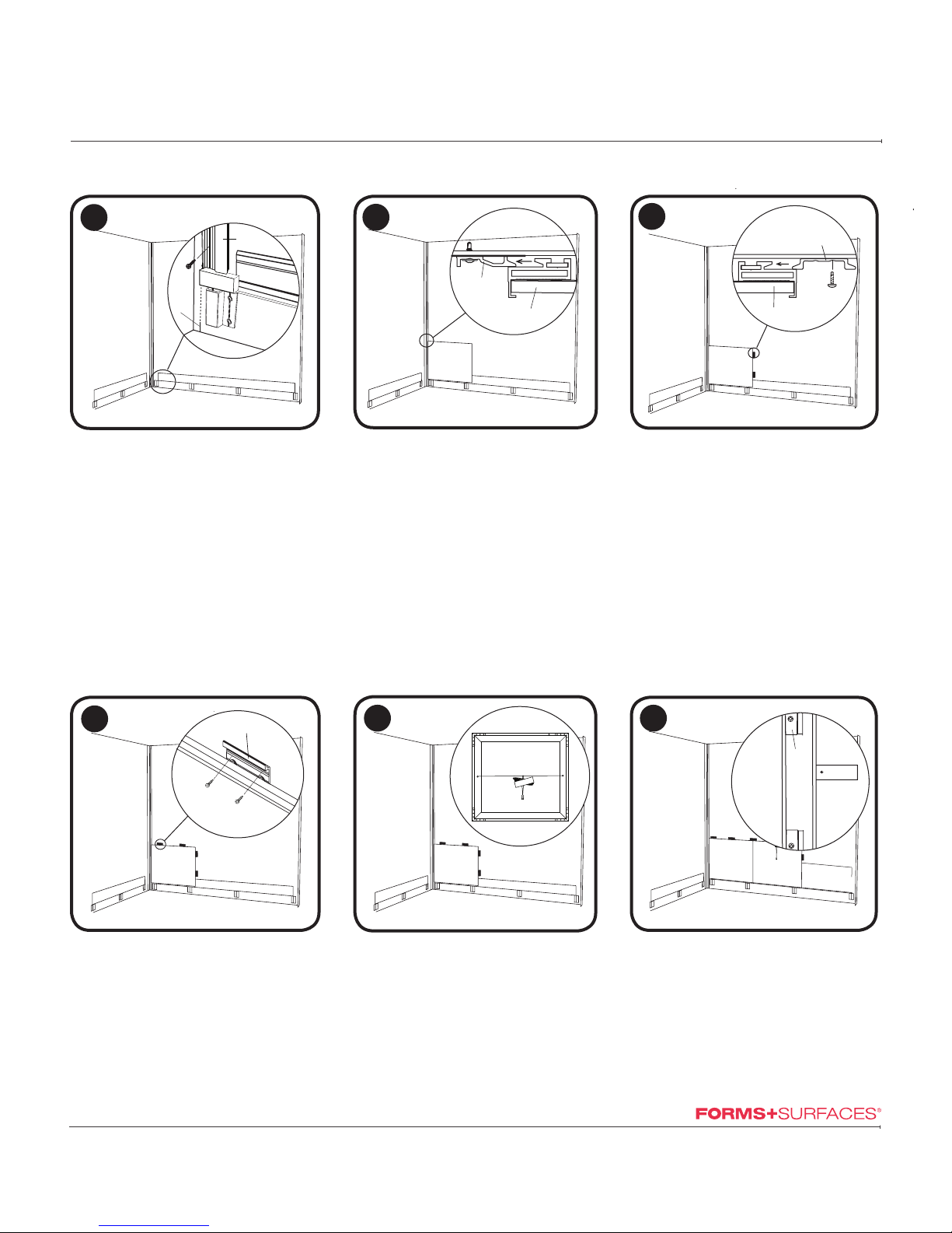
Install (1) Mounting Extrusion
• Align Mounting Extrusion vertically with
the endpoint. Use the provided 1" spacer
above the Base Support to set the
Mounting Extrusion at the proper height.
• Be sure the mounting extrusion is square
relative to the base.
• Attach using provided self-drilling screws.
• Install (1) Mounting Extrusion per side
wall. If LightPlane Panels are adjacent
to Mounting Extrusion, the extrusion will
need to be cut to avoid damage to the
exit wire(s).
78
Install 1st Panel.
• Remove debris from Mounting Extrusion
and Base Cleat with a brush prior to
installation.
• The first panel will engage into the vertical
Mounting Extrusion and Base Cleat.
• It is important that lower panels are
installed straight and level, and engage
fully with the mounting extrusion.
9
Attach side Panel Clips.
• Attach the clips as shown, using the provided
self-drilling screws.
• One panel clip should be installed every
18-24" for proper alignment. Note: Detail is
top view.
10
Install top Panel Clips.
• Attach the clips as shown, using the provided
self-drilling screws.
• One panel clip should be installed every 18-
24" for proper alignment.
REAR
SIDE REARSIDE REARSIDE
REARSIDE
Installed Panel
Panel Clip
TOP VIEW
Installed Panel
Panel Clip
Panel
Mounting
Extrusion
TOP VIEW
1" Spacer
End
Point
Mark
Mounting
Extrusion
11
Identify LightPlane Panel(s).
• LightPlane Panels will arrive with attached
leads and quick connects zip tied on back side
of panels.
• Cut zip ties and place leads on front of panel.
• LEVELe LightPlane Panels are installed using
the same steps as LEVELe panels. LightPlane
Panels have an attached, visible power lead.
BACK VIEW 12
Install Panel Clips to side of panel.
• Attach the clips as shown, using the provided
self-drilling screws.
• One panel clip should be installed every
18-24" for proper alignment, but panel clips
should not obstruct wire exit locations, as
indicated on LightPlane Panels.
CAUTION
DO NOT OBSTRUCT
WIRE EXIT LOCATIONS
Installed
Panel
LightPlane
Panel
Panel
Clip
T 1.800.451.0410 | F 412.781.7840 | www.forms-surfaces.com
page 4 of 7 | 10-16-17
LEVELe®ELEVATOR INTERIORS WITH LIGHTPLANE
INSTALLATION INSTRUCTIONS
© 2017 Forms+Surfaces® | All dimensions are nominal. Specifications and pricing subject to change without notice. For the most current version of this document, please refer to our website at www.forms-surfaces.com.
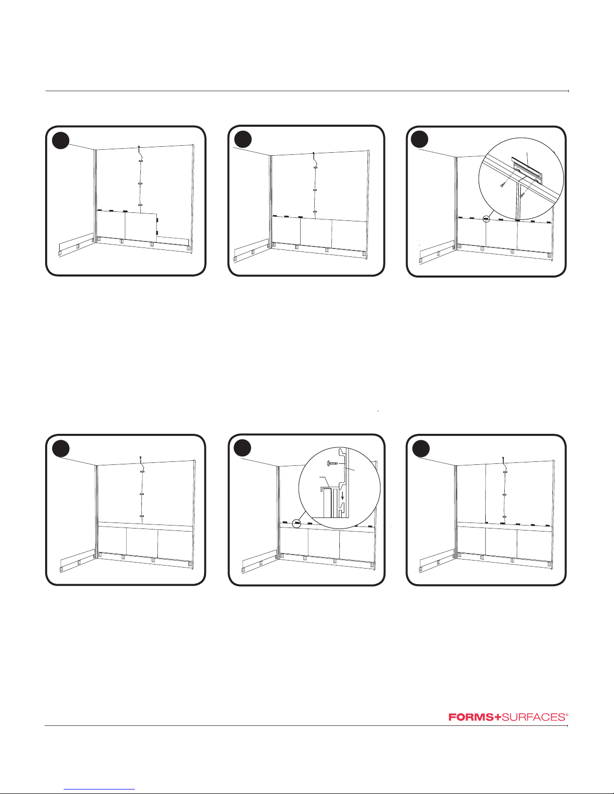
Repeat steps 8-10 as required.
• No side Panel Clips are installed for last panel
of row.
• At any point where two panels meet, Panel
Clips should cross over both panels, as
seen above, to ensure ideal panel alignment.
15
Install Handrail Panel.
• Configurations with a handrail panel come
with handrails factory installed on a single
panel.
• For configurations in which handrails must
span multiple panels, shoulder bolts will be
installed. Once all panels are installed, slide
handrail onto shoulder bolts and tighten
underside set screws with provided allen key.
16 17 18
REAR
SIDE
REARSIDE
Install top Panel Clips.
• Attach the clips as shown, using the provided
self-drilling screws.
• One panel clip should be installed every 18-
24" for proper alignment.
REAR
SIDE REARSIDE
Continue to Install Panels in sequence.
• Rest the first upper panel on the Panel Clips
to position the first upper panel over the
Handrail Panel. Refer to step 8 for detail.
Panel 1
Panel Clip
Panel 2
Installed
Panel Panel Clip
SIDE VIEW
14
REAR
SIDE
Install next Panel in sequence.
• Using the installation sequence document
provided with your elevator interiors, install
panels in the order indicated using the
method described in steps 8-10.
• Panels must engage fully with Hanging
Clips and Panel Clips.
• Debris in the Hanging Clips, Mounting
Extrusion or Panel Clips will prevent the
panel from engaging fully.
13
Attach lead to elevator interior wall.
• Attach the lead(s) to the wall with masking
tape.
• There will be enough lead for the quick
connect to reach the cab shell ceiling. The
lead will run through the milled slot in the
frame.

T 1.800.451.0410 | F 412.781.7840 | www.forms-surfaces.com
page 5 of 7 | 10-16-17
LEVELe®ELEVATOR INTERIORS WITH LIGHTPLANE
INSTALLATION INSTRUCTIONS
© 2017 Forms+Surfaces® | All dimensions are nominal. Specifications and pricing subject to change without notice. For the most current version of this document, please refer to our website at www.forms-surfaces.com.
19 20
REAR
SIDE
Install Panel Clips.
• Attach the clips as shown, using the
provided self-drilling screws.
See step 9 for detail.
• One panel clip should be installed every
18-24" for proper alignment.
REARSIDE
Repeat steps 18-19 as required.
• No side Panel Clips are installed for last
panel in row.
22 23
21
REAR
SIDE
Repeat steps 5-21 for remaining walls.
• Install all panels for remaining walls as
indicated in previous steps.
Install (2) Cover Extrusions on each wall.
• Cover the screws and Mounting Extrusion
with the Cover Extrusion provided.
• The Cover Extrusion is backed with
factory supplied foam tape.
Install (1) Mounting Extrusion on remaining
side of rear wall.
• Position Mounting Extrusion and attach
using provided self-drilling screws.
• If LightPlane Panels are adjacent to Mounting
Extrusion, the extrusion will need to be cut to
avoid damage to the exit wire(s).
• Mounting Extrusion must engage fully with
panels.
REARSIDE REAR
SIDE
Installed
Panel
Mounting
Extrusion
TOP VIEW
Installed Panel
Mounting
Extrusion
Cover Extrusion
VHB Tape
TOP VIEW LightPlane Panels
Power Source
24 LightPlane Panel
Lead with
Quick Connect
Secure LightPlane Panel power source to
cab shell ceiling.
• Mount the LightPlane Panel power box
securely to the cab shell ceiling.
• The LightPlane Panel leads will be fed
through an opening in the cab shell
ceiling.

T 1.800.451.0410 | F 412.781.7840 | www.forms-surfaces.com
page 6 of 7 | 10-16-17
LEVELe®ELEVATOR INTERIORS WITH LIGHTPLANE
INSTALLATION INSTRUCTIONS
© 2017 Forms+Surfaces® | All dimensions are nominal. Specifications and pricing subject to change without notice. For the most current version of this document, please refer to our website at www.forms-surfaces.com.
25
Connect power source to LightPlane
panel lead(s).
• Using the quick connects, attach the
LightPlane Panel leads to the power box
leads.
• Adjust the LightPlane Panel potentiometer
to desired brightness prior to installing the
ceiling.
• Secure excess lead to ceiling to keep it
out of view.
Attach U-bolts to elevator shell.
• Attach U-Bolt using provided retainer
clip, washers and 3/8" - 16 flange nut.
26
Hang ceiling from U-bolts.
• Lift ceiling, engaging U-Bolts into
hanging clip on ceiling.
27
Adjust the position of the ceiling.
• Slide ceiling to center between wall panels.
Position retainer and locking disc.
• Slide retainer and locking disk against
bracket.
Secure elevator ceiling.
• Tighten set screw in locking disk with
provided allen key to secure the ceiling in
place.
28 29 30
4"

T 1.800.451.0410 | F 412.781.7840 | www.forms-surfaces.com
page 7 of 7 | 10-16-17
LEVELe®ELEVATOR INTERIORS WITH LIGHTPLANE
INSTALLATION INSTRUCTIONS
© 2017 Forms+Surfaces® | All dimensions are nominal. Specifications and pricing subject to change without notice. For the most current version of this document, please refer to our website at www.forms-surfaces.com.
32
REAR
SIDE
Install Base Facing.
• Complete the installation by installing the
bases.
• Remove backer from VHB tape on Base
Supports.
• The Base Facing will engage with the
previously installed Base Cleat. Center Base
Facing, aligning with end point markings.
• Press firmly to secure Base Facing to VHB
tape on Base Supports.
Base
Cleat
Base
Facing Base
Support
SIDE VIEW
31
Connect Ceiling Power Box to local power.
• Remove the cover from the power box.
• Insert the local power supply conduit into the
power box opening.
• Secure the ground wire to the junction point.
• Return the cover to the power box and secure
with provided screws.
• Remove the backer from the factory-installed
VHB tape on the bottom of the power box,
and secure it to the cab ceiling.


