-Non utilizzare tensione di alimentazione o tipo di lampada diversi da quelli
indicati
-Durante l’utilizzo del faro, si potrebbero generare elevate temperature . Non
porre vicino l’apparecchio oggetti infiammabili o esplosivi, non toccare la testa del
faro direttamente con le mani
-Assicurarsi che la distanza del faro da tutti gli altri oggetti sia almeno di mt. 1
-Non guardare direttamente la lampada, ciò potrebbe provocare danni agli occhi.
ACCESSORI COMPRESI NELL’IMBALLO
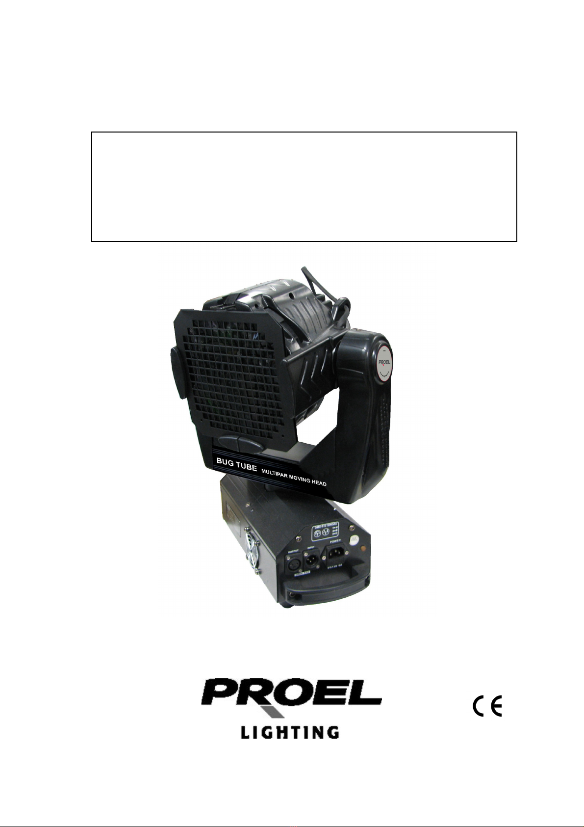
-Proiettore (pz.1)
-Cavo XLR (pz.1)
-Manuale di istruzioni (pz.1)
-Ganci di sicurezza
ISTRUZIONI PER L’INSTALLAZIONE
-Questo prodotto è adatto per uso interno, la massima temperatura dell’ambiente
all’interno del quale deve operare deve essere inferiore a 35°C.
-Le persone addette all’installazione, al funzionamento ed alla manutenzione del
prodotto, devono avere familiarità con le caratteristiche degli apparecchi per
illuminazione, prima che essi possanointraprendere le varie operazioni
sull’apparecchio stesso. La maggior parte dei danni derivano da azioni non
corrette, derivanti dalla non familiarità con le caratteristiche dei proiettori.
-Prima di utilizzare per la prima volta il prodotto, aprire l’imballo per accertarsi che
non ci siano danni provocati durante il trasporto.
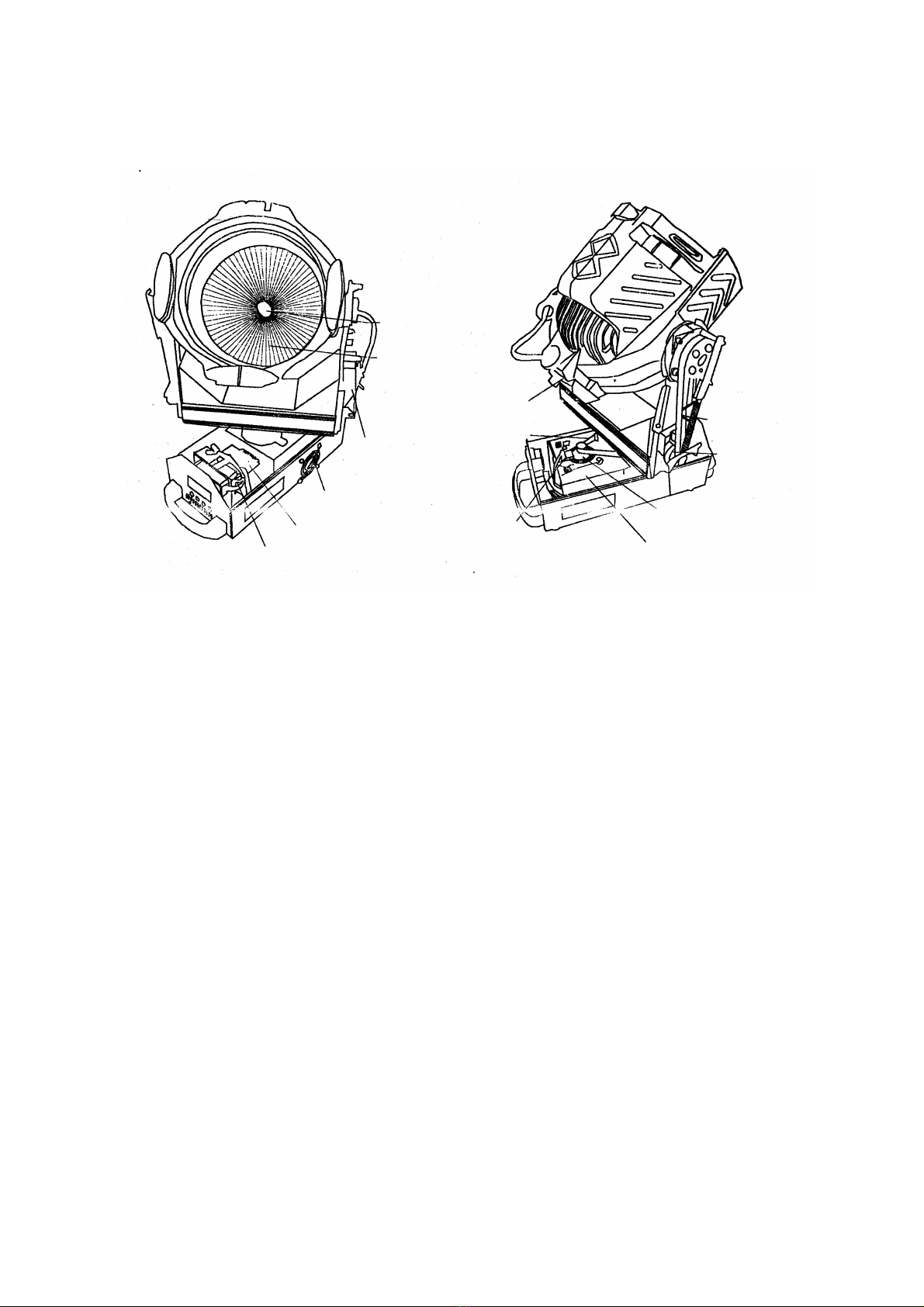
-Prima di sostituire la lampada, assicurarsi che l’apparecchio sia scollegato dalla
rete e che la lampada si sia raffreddata (la temperatura della stessa può
raggiungere i 200°C).
-Aprire il coperchio dell’alloggiamento e sostituire la lampada. Prestare attenzione
a non toccare la superficie della nuova lampada.
-Chiudere il coperchio.
-Installare l’apparecchio in una zona aerata. Assicurarsi che le ventole funzionino
correttamente e che le griglie di aerazione siano libere.
-Il BUG TUBE PAR64 Moving Head, utilizza un fusibile di sicurezza 3A / 250V.
Utilizzare un fusibile dalle stesse caratteristiche.
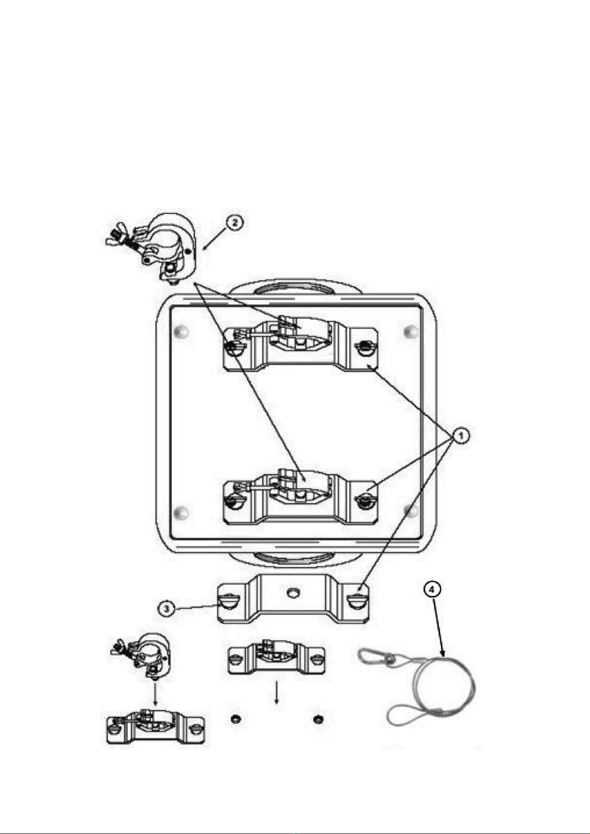
INSTALLAZIONE DEL PROIETTORE
PERICOLO: durante l’installazione considerare sempre le norme del proprio Stato.
L’installazione deve essere sempre eseguita da personale autorizzato.
L’installazione del proiettore deve essere sempre resa sicura attraverso un ancoraggio
secondario di sicurezza (fune di sicurezza). Questo deve essere fatto in modo che
niente possa cadere nell’eventualità che l’ancoraggio principale venga meno.
Una fune di sicurezza, già sottoposta a tensione a causa di una caduta di un
proiettore, o comunque danneggiata, non deve essere mai riutilizzata
1. sostegni a omega (per collegamento alla truss)
2. gancio di fissaggio alla truss (es. aliscaf -opzionale)
3. vite