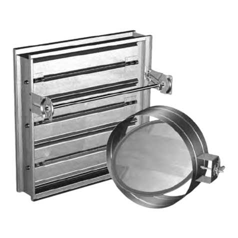
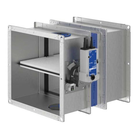
Formula Air AADA Series User manual

Maintenance manual | Electro-pneumatic sliding dampers
www.formula-air.com
1
Pneumatic sliding dampers
AADA, ABDB, CADB & CBDB
Maintenance manual (EN)
V1.0-2021

Maintenance manual | Electro-pneumatic sliding dampers
www.formula-air.com
2
Content
1. Introduction ..................................................................................................................................................... 3
1.1. How it works........................................................................................................................................... 3
1.2. Product code description ........................................................................................................................ 4
1.3. Catalogue options .................................................................................................................................. 4
2. Technical information....................................................................................................................................... 4
2.1. Sliding damper composition .................................................................................................................... 4
2.1.1 For sliding dampers with ROUND cylinders ............................................................................................. 5
2.1.2 For sliding dampers with SQUARE cylinders ............................................................................................ 6
2.2. Overall dimensions.................................................................................................................................. 6
2.3. Electro-pneumatic solenoid valve details ................................................................................................ 7
3. MOUNTING INSTRUCTIONS ........................................................................................................................... 7
3.1. Tools needed for mounting...................................................................................................................... 7
3.2. Mounting the cylinders on the body......................................................................................................... 8
3.2.1 For sliding dampers with ROUND cylinders ............................................................................................. 8
3.2.2 For sliding dampers with SQUARE cylinders ............................................................................................ 9
3.3. Mounting the solenoid valve on the Sliding damper body...................................................................... 10
3.3.1 Mounting the solenoid valve on the sliding damper body...................................................................... 10
3.3.2 Mounting the coil and connector on the solenoid valve......................................................................... 10
3.3.3 Connection of electro-pneumatic solenoid valve................................................................................... 10
3.4. Compressed air connection................................................................................................................... 10
3.5. Mounting the reed sensors on the cylinders (optional) ........................................................................... 11
3.5.1 Mounting the reed sensors on the ROUND cylinder (optional) ............................................................... 11
3.5.2 Mounting the reed sensors on the SQUARE cylinder (optional) .............................................................. 11
3.5.3 Electrical connection of the reed sensor ................................................................................................ 12
3.6. Mounting the cover house on the sliding damper body (optional) .......................................................... 12
3.7. Placing the sliding damper in an installation ......................................................................................... 12
4. Maintenance, spare parts and troubleshooting.............................................................................................. 14
4.1. Precautions for proper use .................................................................................................................... 14
4.2. Maintenance ........................................................................................................................................ 14
4.2.1 Periodic maintenance of the sliding damper................................................................................. 14
4.3. Replacing spare parts........................................................................................................................... 14
4.3.1 Replacing the pneumatic cylinder ......................................................................................................... 14
4.3.2 Replacing the electro-pneumatic solenoid valve................................................................................... 14
4.3.3 Replacing the air hoses......................................................................................................................... 14
4.3.4 Replacing the reed sensors ................................................................................................................... 14
4.3.5 Replacing the cover house.................................................................................................................... 14
4.4. Troubleshooting .................................................................................................................................... 15
5. Dismantling and recycling.............................................................................................................................. 15
6. Maintenance log ........................................................................................................................................... 16
Contacts................................................................................................................................................................. 17

Maintenance manual | Electro-pneumatic sliding dampers
www.formula-air.com
3
1. Introduction
This manual cannot be reproduced, even partially, without prior written consent by Formula Air Group. Every step of
the electro-pneumatic sliding damper range has been deeply analyzed by Formula Air Group in the expected area
during the design, construction, and user manual creation. However, it is understood that nothing can replace the
experience, training and good sense of those professionals who work with the device.
Ignoring the cautions and warning from the present user manual, using improperly parts or the whole device supplied,
using unauthorized spare parts, manipulating the device by non-qualified personnel, violation of any safety norm
regarding design, construction and use expected by the supplier, exempt Formula Air Group from all responsibility in
case of damages to people or properties.
Formula Air Group does not take any responsibility for the non-observance of the user about the preventive safety
measures presented in this user manual.
Failure to comply with the requirements of the user manual or incorrect use of the electro-pneumatic sliding damper
during operation can lead to the damage of the electro-pneumatic sliding damper and improper functioning of the
electro-pneumatic sliding damper itself. This will result in termination of the warranty on the item and will release the
manufacturer from any liability.
Warranty
Regarding to the device’s warranty, see the sales general condition.
Attention !
All drawings and references contained within this user manual are non-contractual and are subject to change without
prior notice at the discretion of the Formula Air Group and its partners.
Copyright © Formula Air.
1.1. How it works
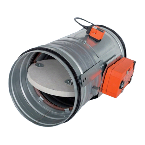
The electro-pneumatic sliding dampers are normally used to shut off or regulate the air flow in duct systems. The
dampers are made of electro-galvanized sheet metal, mounted with PEHD and rubber seals to ensure optimum
tightness.
Note that they are meant to be installed within a complete installation needs to comply to :
2006/42/EU – Machine Directive
2014/35/EU – Low Voltage Equipment Directive
2014/30/EU – Electromagnetic Compatibility and Repealing Directive (EMC)
The electro-pneumatic sliding dampers are designed to control the air flow through the ducting system by sliding a
sheet metal blade.

Maintenance manual | Electro-pneumatic sliding dampers
www.formula-air.com
4
CLOSED POSITION OPENED POSITION
1.2. Product code description
AADA : Medium pressure electro-galvanized sliding damper
ABDB :Medium pressure stainless steel sliding damper
CADB :High pressure electro-galvanized sliding damper
CBDB :High pressure stainless steel sliding damper
1.3. Catalogue options
The standard Pneumatic sliding dampers are available with the following configurations :
- Different solenoid valve models :
- Electro-pneumatic (standard)
- Double acting electro-pneumatic
- Full pneumatic
- Manual pneumatic with joystick
- Different tensions for the electro-pneumatic versions :
- 24 V AC
- 24 V DC
- 48 V DC
- 110 V AC
- 220 V AC
- Other options that can be ordered separately :
- Reed sensors
- Cover houses
- Diameters up to Ø160 with double cylinders
- Other brand pneumatic components (Festo)
2. Technical information
2.1. Sliding damper composition
The pneumatic sliding dampers are equipped with one cylinder up to Ø160 but it is designed to fit two cylinders on
request when needed. The sliding dampers as of Ø180 and up are equipped with two cylinders as a standard.
An electro-pneumatic solenoid valve is included on every model.
The Cover house is optional to protect the user from the moving parts.
Position detectors are optional as well to indicate the position of the cylinder (and sliding damper blade).

Maintenance manual | Electro-pneumatic sliding dampers
www.formula-air.com
5
2.1.1 For sliding dampers with ROUND cylinders
Picture
Part
Quantity
Body – ready for – AADS
1
Solenoid valve with connectors
1 (from Ø80 up to Ø160)
Solenoid valve with T connectors
1 (from Ø180 up to Ø500)
Pneumatic cylinder
1 (up to Ø160)
or
2 (from Ø180 up to Ø500)
Bolt M4 x 25
2
Bolt M8 x 40
1 (up to Ø160)
2 (from Ø180 up to Ø250)
Bolt M12 x 60 2 (from Ø275 up to Ø500)
Flat washer for M4
2
Flat washer for M8
1 (up to Ø160)
2 (from Ø180 up to Ø250)
Flat washer for M12
2 (from Ø275 up to Ø500)
Hexagon nut M10
1 (up to Ø160)
2 (from Ø180 up to Ø250)
Hexagon nut M12
2 (from Ø275 up to Ø500)
Lock nut M8
1 (up to Ø160)
2 (from Ø180 up to Ø250)
Lock nut M12
2 (from Ø275 up to Ø500)
Plastic spacer
1 (up to Ø160)
2 (from Ø180 up to Ø500)
Air hose
Variable depending on damper size
Cover house (Optional)
1
Position sensor (Optional) Normally 2 per cylinder
Position sensor strap (Optional)
2 (up to Ø160)
4 (from Ø180 up to Ø500)

Maintenance manual | Electro-pneumatic sliding dampers
www.formula-air.com
6
2.1.2 For sliding dampers with SQUARE cylinders
Picture
Part
Quantity
Body – ready for – AADS
1
Solenoid valve with connectors
1 (from Ø80 up to Ø160)
Solenoid valve with T connectors
1 (from Ø180 up to Ø500)
Pneumatic cylinder
1 (from Ø80 up to Ø160)
Or
2 (from Ø180 up to Ø500)
Cylinder holder
1 (from Ø80 up to Ø160)
Or
2 (from Ø180 up to Ø500)
Bolt M4 x 25
1 or 2
Bolt M8 x 40
8 or 16
Bolt M8 x 20
2 or 4
Washer for M4
1 or 2
Washer for M8 10 or 20
Nut M8
2 or 4
Nut M16
1 or 2
Air hose
Variable depending on damper
size
Cover house (Optional)
1
Position sensor (Optional) Normally 2 per cylinder
2.2. Overall dimensions

Maintenance manual | Electro-pneumatic sliding dampers
www.formula-air.com
7
Ø
D int.
Edge
L1
L2
L3
L4
H
S1
S2
Kg
50
47
gl
139
173
128
301
245
1.5
2.0
2.4
63 60 gl 139 173 128 301 245 1.5 2.0 2.5
76
73
gl
157
195
150
345
245
1.5
2.0
2.6
80
80
fb
157
195
150
345
125
1.5
2.0
2.6
89
86
gl
177
225
180
405
245
1.5
2.0
2.9
100 100 fb 177 225 180 405 125 1.5 2.0 3.3
102
99
gl
177
225
180
405
245
1.5
2.0
3.7
114 111 gl 201 264 217 482 245 1.5 2.0 3.8
120
120
fb
200
264
217
482
125
1.5
2.0
3.9
125 125 fb 200 264 217 482 125 1.5 2.0 4.2
127
124
gl
200
264
217
182
245
1.5
2.0
4.3
140 140 fb 225 300 255 555 125 1.5 2.0 4.8
150
150
fb
225
300
255
555
125
1.5
2.0
4.8
152 149 gl 225 300 255 555 245 1.5 2.0 4.9
160
160
fb
235
314
270
584
125
1.5
2.0
5.1
180
180
fb
276
378
330
708
125
1.5
2.0
6.9
200
200
fb
276
378
330
708
125
1.5
2.0
7.1
203 200 gl 276 378 330 708 245 1.5 2.0 7.2
225
225
fb
345
452
405
857
165
2.0
3.0
13.3
250 250 fb 370 454 405 859 165 2.0 3.0 13.3
275
275
fb
421
546
513
108
165
2.0
3.0
19.7
300
300
fb
421
546
513
1058
165
2.0
3.0
20.6
315
315
fb
436
546
513
1058
165
2.0
3.0
20.6
350 350 fb 473 607 635 1162 165 2.0 3.0 27.9
400
400
fb
521
682
635
1316
165
2.0
3.0
40.9
450 450 fb 622 770 721 1491 224 3.0 4.0 59.5
500
500
fb
672
845
790
1635
224
3.0
4.0
67.8
2.3. Electro-pneumatic solenoid valve details
Solenoid
valve type
Action
Operating
pressure
Min. response
time
Working Tº Nº cylinders
From Ø 80 up to
Ø 160 2/5 way -
G1/8
Single
acting
1.5 - 8.0
kgf/ cm20.05 s 5 - 60 ºC
1
From Ø 180 up to
Ø 500 2
3. MOUNTING INSTRUCTIONS
3.1. Tools needed for mounting
Loctite, Hex screwdrivers, Nut driver, wrenches, screwdrivers and diagonal cutters.

Maintenance manual | Electro-pneumatic sliding dampers
www.formula-air.com
8
CAUTION ! The mounting of the sliding damper has to be performed by qualified personnel only. Before starting
assembling, check that you have all the parts and the correct tools for mounting.
CAUTION ! Make sure to wear the appropriate protective clothing, gloves, eye protection and masks when
needed.
3.2. Mounting the cylinders on the body
3.2.1 For sliding dampers with ROUND cylinders
Step 1 :
Insert the head of the cylinder body through the hole in the top of the sliding damper body.
Step 2 :
Tighten the top of the cylinder with the big counter nut.
Step 3 :
Attach the base of the cylinder to the body using nuts, counter-nuts and spacers.
IMPORTANT : Make sure that the cylinder is aligned with the body to ensure proper blade movement and
avoid premature wear of the components.
Step 4 :
Pull the sliding damper blade completely out (make sure that the hole in the middle of the blade is
aligned with the pipe pieces of the sliding damper body).
Step 5 :
Pull out the cylinder rod, pass it through the hole at the top of the sliding damper blade, and tighten
the two counter nuts using a bit of Loctite.
Bolt
Spacer
Lock nut and
washers
Nut
Counter-nut

Maintenance manual | Electro-pneumatic sliding dampers
www.formula-air.com
9
Step 6 :
Repeat steps 1 to 5 if the sliding damper is equipped with two cylinders.
3.2.2 For sliding dampers with SQUARE cylinders
Step 1 :
Screw the cylinder support to the base of the cylinder with the washers and bolts.
Step 2 :
Insert the head of the cylinder through the hole in the top of the sliding damper body.
Step 3 :
Screw the head of the cylinder body to the sliding damper body with washers and bolts.
Step 4 :
Secure the cylinder support to the damper body using bolts, washers and nuts.
Step 5 :
Pull the sliding damper blade completely out (make sure that the hole in the middle of the blade is
aligned with the pipe pieces of the sliding damper body).
Step 6 :
Pull out the cylinder rod, pass it through the hole at the top of the sliding damper blade, and tighten
the two counter-nuts using a bit of Loctite.
Step 7 :
Repeat steps 1 to 6 if the sliding damper is equipped with two cylinders.
Bolt
Washer
Bolt
Nut
Washer
Bolt
Washer
Nut
Counter-nut

Maintenance manual | Electro-pneumatic sliding dampers
www.formula-air.com
10
3.3. Mounting the solenoid valve on the Sliding damper body
3.3.1 Mounting the solenoid valve on the sliding damper body
Step 1 :
Place the solenoid valve over the threaded holes on the sliding damper body.
Step 2 :
Screw the solenoid valve to the body with Hex-screws and washers.
3.3.2 Mounting the coil and connector on the solenoid valve
CAUTION ! Make sure that all electrical connections have been disconnected.
Step 1 :
Unscrew the plastic cap on the head of the solenoid valve, slide the coil over the coil shaft, and tighten
the plastic cap to hold the coil in place.
Step 2 :
connect the connector on the coil by sliding it over the three prongs of the coil and lock it in place with
the screw on the top of the connector.
NOTE :it is easier to first connect the electrical wiring of the connector before placing it on the coil.
3.3.3 Connection of electro-pneumatic solenoid valve
3.4. Compressed air connection
CAUTION ! Make sure that the air supply and all electrical connections have been disconnected.
Step 1 :
Take a compressed air hose size 4/6 mm. Push the hose in one of the cylinder swivel elbows, and
connected to the air hose connector on the electro-pneumatic solenoid valve.
Bolts and
washers
Connector
Coil plastic cap
Coil
Valve body

Maintenance manual | Electro-pneumatic sliding dampers
www.formula-air.com
11
Step 2 :
Repeat for the other side of the cylinder. Then repeat to the other cylinder (if there is a second cylinder
on the damper).
Step 3 :
Connect the air hose supply to the male stud connection on the other side of the electro-pneumatic
solenoid valve (the side with the two regulators).
CAUTION ! We recommend using 6 Bar compressed air. DO NOT EXCEED 8 Bar !!
3.5. Mounting the reed sensors on the cylinders (optional)
3.5.1 Mounting the reed sensors on the ROUND cylinder (optional)
Step 1 :
place reed sensor strap around the cylinder body, place the reed sensor inside it.
Step 2
: Tighten the small screw on the head of the strap to hold it in place in the desired position.
3.5.2 Mounting the reed sensors on the SQUARE cylinder (optional)
Step 1
: Slide the reed sensor in the slits along the side of the cylinder.
Step 2
: Tighten the small screw on the reed sensor body to hold it in place at the desired position.
NOTE : To ensure proper functioning, make sure that the reed sensors are placed at maximum 3 cm from the
edges of the cylinder body.
Reed sensor
≈ 3 cm
Reed sensor
≈ 3 cm

Maintenance manual | Electro-pneumatic sliding dampers
www.formula-air.com
12
3.5.3 Electrical connection of the reed sensor
3.6. Mounting the cover house on the sliding damper body (optional)
Step 1
:Unscrew the bolt from the damper body where the cover house goes.
Step 2 :
Slide the cover over the sliding damper body.
Step 3 :
Use the bolt unscrewed in Step 1 to attach it to the sliding damper.
3.7. Placing the sliding damper in an installation
Step 1 :
Attach the sliding damper to the ducting, using suitable rings. Seals can be added to the rings for extra air-
tightness.

Maintenance manual | Electro-pneumatic sliding dampers
www.formula-air.com
13
IMPORTANT :Make sure to use adequate support on the pipes on either side of the sliding damper to reduce
pressure on the sliding damper body and blade.
Recommended mounting in horizontal ducting is to have the blade open downwards, and have the sliding damper
body supported with suspension rings at most at 150 mm from either side of the sliding damper edges.
Step 2 :
Connect the compressed air hose and the electrical power to the solenoid valve.
Step 3 :
Adjust the opening and closing speed of the sliding damper by turning the screw on the air regulators, on the
side of the solenoid valve.
NOTE
:
only use oil and water free, dry compressed air for proper functioning.
Attach together
with pull rings
Attach together
with pull rings
Air hose connection
Air regulators
≈ 150 cm
≈ 150 cm
Suspension rings

Maintenance manual | Electro-pneumatic sliding dampers
www.formula-air.com
14
4. Maintenance, spare parts and troubleshooting
The installation, connection, start-up and maintenance of the sliding damper has to be performed by qualified
personnel only.
4.1. Precautions for proper use
CAUTION ! It is strictly forbidden to work on the electro-pneumatic sliding damper while the installation is running.
During maintenance keep the system disconnected and all the electrical equipment turned off.
4.2. Maintenance
All electro-pneumatic components are maintenance free during the life cycle of the product.
4.2.1 Periodic maintenance of the sliding damper
In order to ensure proper functioning and long life of the product, regular maintenance must be carried out.
Maintenance must always be carried out according to the instructions in the manual.
Make sure that the bolts are all tight, that the air hose and electrical cable are intact and that no leakage is detected.
4.3. Replacing spare parts
If needed, some parts of the damper can be replaced : seals, pneumatic cylinders, air hose, electro-pneumatic
solenoid valve, cover house and reed sensors.
CAUTION ! Before any manipulation, make sure that the installation is stopped and that all compressed air and
electrical connections are disconnected.
NOTE : all electrical manipulations should be performed by qualified personnel only.
4.3.1 Replacing the pneumatic cylinder
Reverse, then repeat steps described in point 3.2 and 3.4.
4.3.2 Replacing the electro-pneumatic solenoid valve
Reverse, then repeat steps described in point 3.3 and 3.4.
4.3.3 Replacing the air hoses
Reverse, then repeat steps described in point 3.4
4.3.4 Replacing the reed sensors
Reverse, then repeat steps described in point 3.5.
4.3.5 Replacing the cover house
Reverse, then repeat steps described in point 3.6.

Maintenance manual | Electro-pneumatic sliding dampers
www.formula-air.com
15
4.4. Troubleshooting
Failure
Possible causes
Proposed solutions
No electrical reaction but
there is compressed air
•No current
•Inverse or wrong wiring
•Connector electrical overload
•Make sure there is nominal current
(point 3.3)
•Refer to the wiring diagram (point
3.3)
•
Replace the connector (point 3.3)
Blade doesn’t open although
there is electricity
•No compressed air
•Not enough compressed air pressure
•Make sure there is compressed air
(point 3.3)
•
Make sure to have +/- 6 Bar
Blade doesn’t open although
there is electricity and
compressed air
•Blade doesn’t slide in line with the body
•Foreign object blocking the blade
•Body and seals exert too much pressure on blade
•Something is pulling the blade
sideways ((point 3.2)
•Remove foreign object
•
Check the seals and body space
Compressed air leakage
•Air hose is not correctly inserted in connections
•Air hose is cracked or deteriorated
•Threaded components are loose
•Pull hose out and re-insert (point 3.4)
•Replace air hose
•Tighten threaded components
Blade opens too fast / too
slow •Air regulators are not tuned to desired position •
Turn the air regulators to desired
airflow (point 3.7)
5. Dismantling and recycling
When dismantling a unit, be sure to keep in mind the following important information:
•As the unit is dismantled, set aside all still functioning parts to re-use them on another unit.
•You should always separate the different materials depending on their type: iron, rubber, oils, greases, etc…
•Recyclable parts must be disposed of in the appropriate containers or brought to a local recycling company.
The rubbish must be collected in special containers with appropriate labels and disposed of in compliance with the
national laws and/or local legislations in force.
CAUTION !
It is strictly forbidden to dispose of toxic wastes in municipal sewerage and drain systems. This concerns all oils,
greases, and other toxic materials in liquid or solid form.

Maintenance manual | Electro-pneumatic sliding dampers
www.formula-air.com
16
6. Maintenance log
date
description

Maintenance manual | Electro-pneumatic sliding dampers
www.formula-air.com
17
Formula Air The Netherlands
Head Office / Production / Sales
Bosscheweg 36
5741 SX Beek en Donk,
The Netherlands
+31 492 45 15 45
info-nl@formula-air.com
Formula Air France – West
Sales
6, avenue des Lions
44800 Saint-Herblain
France
+33 9 72 15 29 38
contact-ouest@formula-air.com
Formula Air France – South
Sales
Chemin de Peyrecave
09600 Regat
France
+33 9 72 15 29 38
contact-sud@formula-air.com
Formula Air Nordic
Sales
Stortorget 17
211 22 Malmö
Sweden
+46 40 654 06 10
info-scan@formula-air.com
Formula Air Belgium
Logistics / Sales
Rue des Dizeaux 4
1360 Perwez
Belgium
+32 81 23 45 71
info-be@formula-air.com
Formula Air France – North
Sales
Zac de la Carrière Dorée
BP 105, 59310 Orchies
France
+33 9 72 15 29 38
contact-fr@formula-air.com
Formula Air Germany
Sales
Dr.-Oetker Straße 10
54516 Wittlich
Germany
+49 6571 269860
info-de@formula-air.com
Formula Air Export
Sales
Rue des Dizeaux 4
1360 Perwez
Belgium
+32 81 23 45 71
info-be@formula-air.com
Formula Air Baltic
Production / Sales
P. Motiekaičio g. 3
LT-77104 Šiauliai
Lithuania
+370 41 54 04 82
info-lt@formula-air.com
Formula Air France – East
Sales
2, rue Armand Bloch
25200 Montbéliard
France
+33 9 72 15 29 38
contact-est@formula-air.com
Formula Air Vietnam
Production / Sales
#33, Lot 2, Den Lu 1
Hoang Mai District, Hanoi
Vietnam
+84 (24) 38 62 68 01
info@vinaduct.com
Contacts
This manual suits for next models
3
Table of contents

