Fortec Elektronik SOM-6867 User manual

The information contained in this document has been carefully researched and is, to the best
of our knowledge, accurate. However, we assume no liability for any product failures or
damages, immediate or consequential, resulting from the use of the information provided
herein. Our products are not intended for use in systems in which failures of product could
result in personal injury. All trademarks mentioned herein are property of their respective
owners. All specifications are subject to change without notice.
Manual
SOM-6867
Advantech
Our company network supports you worldwide with offices in Germany, Austria,
Switzerland, Great Britain and the USA. For more information please contact:
FORTEC Elektronik AG
Hauptniederlassung
Lechwiesenstr. 9
86899 Landsberg am Lech
Telefon: +49 (0) 8191 91172-0
Telefax: +49 (0) 8191 21770
E-Mail: [email protected]
Internet: www.fortecag.de
FORTEC Elektronik AG
Büro West
Hohenstaufenring 55
50674 Köln
Telefon: +49 (0) 221 272 273-0
Telefax: +49 (0) 221 272 273-10
E-Mail: [email protected]
Internet: www.fortecag.de
FORTEC Elektronik AG
Büro Wien
Nuschinggasse 12
A-1230 Wien
Telefon: +43 1 8673492-0
Telefax: +43 1 8673492-26
E-Mail: [email protected]
Internet: www.fortec.at
ALTRAC AG
(Tochter der FORTEC):
Bahnhofstraße 3
CH-5436 Würenlos
Telefon: +41 (0) 44 7446111
Telefax: +41 (0) 44 7446161
E-Mail: [email protected]
Internet: www.altrac.ch

User Manual
SOM-6867

SOM-6867 User Manual ii
Copyright
The documentation and the software included with this product are copyrighted 2015
by Advantech Co., Ltd. All rights are reserved. Advantech Co., Ltd. reserves the right
to make improvements in the products described in this manual at any time without
notice. No part of this manual may be reproduced, copied, translated or transmitted
in any form or by any means without the prior written permission of Advantech Co.,
Ltd. Information provided in this manual is intended to be accurate and reliable. How-
ever, Advantech Co., Ltd. assumes no responsibility for its use, nor for any infringe-
ments of the rights of third parties, which may result from its use.
Acknowledgements
Intel® and Pentium® are trademarks of Intel Corporation.
Microsoft Windows and MS-DOS are registered trademarks of Microsoft Corp.
All other product names or trademarks are properties of their respective owners.
Product Warranty (2 years)
Advantech warrants to you, the original purchaser, that each of its products will be
free from defects in materials and workmanship for two years from the date of pur-
chase.
This warranty does not apply to any products which have been repaired or altered by
persons other than repair personnel authorized by Advantech, or which have been
subject to misuse, abuse, accident or improper installation. Advantech assumes no
liability under the terms of this warranty as a consequence of such events.
Because of Advantech’s high quality-control standards and rigorous testing, most of
our customers never need to use our repair service. If an Advantech product is defec-
tive, it will be repaired or replaced at no charge during the warranty period. For out-
of-warranty repairs, you will be billed according to the cost of replacement materials,
service time and freight. Please consult your dealer for more details.
If you think you have a defective product, follow these steps:
1. Collect all the information about the problem encountered. (For example, CPU
speed, Advantech products used, other hardware and software used, etc.) Note
anything abnormal and list any onscreen messages you get when the problem
occurs.
2. Call your dealer and describe the problem. Please have your manual, product,
and any helpful information readily available.
3. If your product is diagnosed as defective, obtain an RMA (return merchandize
authorization) number from your dealer. This allows us to process your return
more quickly.
4. Carefully pack the defective product, a fully-completed Repair and Replacement
Order Card and a photocopy proof of purchase date (such as your sales receipt)
in a shippable container. A product returned without proof of the purchase date
is not eligible for warranty service.
5. Write the RMA number visibly on the outside of the package and ship it prepaid
to your dealer.
Part No. 2006686700 Edition 1
Printed in Taiwan March 2015

iii SOM-6867 User Manual
Declaration of Conformity
CE
This product has passed the CE test for environmental specifications. Test conditions
for passing included the equipment being operated within an industrial enclosure. In
order to protect the product from being damaged by ESD (Electrostatic Discharge)
and EMI leakage, we strongly recommend the use of CE-compliant industrial enclo-
sure products.
FCC Class B
Note: This equipment has been tested and found to comply with the limits for a Class
B digital device, pursuant to part 15 of the FCC Rules. These limits are designed to
provide reasonable protection against harmful interference in a residential installa-
tion. This equipment generates, uses and can radiate radio frequency energy and, if
not installed and used in accordance with the instructions, may cause harmful inter-
ference to radio communications. However, there is no guarantee that interference
will not occur in a particular installation. If this equipment does cause harmful interfer-
ence to radio or television reception, which can be determined by turning the equip-
ment off and on, the user is encouraged to try to correct the interference by one or
more of the following measures:
Reorient or relocate the receiving antenna.
Increase the separation between the equipment and receiver.
Connect the equipment into an outlet on a circuit different from that to which the
receiver is connected.
Consult the dealer or an experienced radio/TV technician for help.
FM
This equipment has passed the FM certification. According to the National Fire Pro-
tection Association, work sites are classified into different classes, divisions and
groups, based on hazard considerations. This equipment is compliant with the speci-
fications of Class I, Division 2, Groups A, B, C and D indoor hazards.
Technical Support and Assistance
1. Visit the Advantech website at http://support.advantech.com where you can find
the latest information about the product.
2. Contact your distributor, sales representative, or Advantech's customer service
center for technical support if you need additional assistance. Please have the
following information ready before you call:
–Product name and serial number
–Description of your peripheral attachments
–Description of your software (operating system, version, application software,
etc.)
–A complete description of the problem
–The exact wording of any error messages
SOM-6867 User Manual iv
Warnings, Cautions and Notes
Document Feedback
To assist us in making improvements to this manual, we would welcome comments
and constructive criticism. Please send all such comments in writing to: sup-
Packing List
Before setting up the system, check that the items listed below are included and in
good condition. If any item does not accord with the table, please contact your dealer
immediately.
SOM-6867 CPU module
1 x Heat spreader (1960065753N001)
Warning! Warnings indicate conditions, which if not observed, can cause personal
injury!
Caution! Cautions are included to help you avoid damaging hardware or losing
data. e.g.
There is a danger of a new battery exploding if it is incorrectly installed.
Do not attempt to recharge, force open, or heat the battery. Replace the
battery only with the same or equivalent type recommended by the man-
ufacturer. Discard used batteries according to the manufacturer's
instructions.
Note! Notes provide optional additional information.

v SOM-6867 User Manual
Safety Instructions
1. Read these safety instructions carefully.
2. Keep this User Manual for later reference.
3. Disconnect this equipment from any AC outlet before cleaning. Use a damp
cloth. Do not use liquid or spray detergents for cleaning.
4. For plug-in equipment, the power outlet socket must be located near the equip-
ment and must be easily accessible.
5. Keep this equipment away from humidity.
6. Put this equipment on a reliable surface during installation. Dropping it or letting
it fall may cause damage.
7. The openings on the enclosure are for air convection. Protect the equipment
from overheating. DO NOT COVER THE OPENINGS.
8. Make sure the voltage of the power source is correct before connecting the
equipment to the power outlet.
9. Position the power cord so that people cannot step on it. Do not place anything
over the power cord.
10. All cautions and warnings on the equipment should be noted.
11. If the equipment is not used for a long time, disconnect it from the power source
to avoid damage by transient overvoltage.
12. Never pour any liquid into an opening. This may cause fire or electrical shock.
13. Never open the equipment. For safety reasons, the equipment should be
opened only by qualified service personnel.
14. If one of the following situations arises, get the equipment checked by service
personnel:
The power cord or plug is damaged.
Liquid has penetrated into the equipment.
The equipment has been exposed to moisture.
The equipment does not work well, or you cannot get it to work according to
the user's manual.
The equipment has been dropped and damaged.
The equipment has obvious signs of breakage.
15. DO NOT LEAVE THIS EQUIPMENT IN AN ENVIRONMENT WHERE THE
STORAGE TEMPERATURE MAY GO BELOW -20° C (-4° F) OR ABOVE 60° C
(140° F). THIS COULD DAMAGE THE EQUIPMENT. THE EQUIPMENT
SHOULD BE IN A CONTROLLED ENVIRONMENT.
16. CAUTION: DANGER OF EXPLOSION IF BATTERY IS INCORRECTLY
REPLACED. REPLACE ONLY WITH THE SAME OR EQUIVALENT TYPE
RECOMMENDED BY THE MANUFACTURER, DISCARD USED BATTERIES
ACCORDING TO THE MANUFACTURER'S INSTRUCTIONS.
The sound pressure level at the operator's position according to IEC 704-1:1982 is
no more than 70 dB (A).
DISCLAIMER: This set of instructions is given according to IEC 704-1. Advantech
disclaims all responsibility for the accuracy of any statements contained herein.

SOM-6867 User Manual vi
Safety Precaution - Static Electricity
Follow these simple precautions to protect yourself from harm and the products from
damage.
To avoid electrical shock, always disconnect the power from your PC chassis
before you work on it. Don't touch any components on the CPU card or other
cards while the PC is on.
Disconnect power before making any configuration changes. The sudden rush
of power as you connect a jumper or install a card may damage sensitive elec-
tronic components.

vii SOM-6867 User Manual
Contents
Chapter 1 General Information ............................1
1.1 Introduction ............................................................................................... 2
1.2 Specifications ............................................................................................ 2
1.2.1 Board Information ......................................................................... 2
1.2.2 System Information ....................................................................... 2
1.2.3 Display .......................................................................................... 3
1.2.4 Expansion Interface ...................................................................... 3
1.2.5 I/O ................................................................................................. 3
1.2.6 iManager 2.0 ................................................................................. 3
1.2.7 Mechanical and Environmental Specification ............................... 4
1.3 Functional Block Diagram ......................................................................... 4
Figure 1.1 Functional Block Diagram........................................... 4
Chapter 2 Mechanical Information ......................5
2.1 Board Information...................................................................................... 6
Figure 2.1 Board Chips Identify - Front........................................ 6
Figure 2.2 Board Chips Identify - Back ........................................ 6
2.1.1 Connector List............................................................................... 7
Table 2.1: FAN1 Fan ................................................................... 7
2.2 Mechanical Drawing.................................................................................. 7
Figure 2.3 Board Mechanical Drawing - Front ............................. 7
Figure 2.4 Board Mechanical Drawing - Back ............................. 8
Figure 2.5 Board Mechanical Drawing - Back ............................. 8
2.3 Assembly Drawing .................................................................................... 9
Figure 2.6 Assembly Drawing...................................................... 9
Chapter 3 BIOS....................................................11
3.1 Entering Setup ........................................................................................ 12
Figure 3.1 Setup Program Initial Screen.................................... 12
3.2 Main Setup .............................................................................................. 13
Figure 3.2 Main Setup Screen ................................................... 13
3.3 Advanced BIOS Features Setup ............................................................. 14
Figure 3.3 Advanced BIOS Features Setup Screen .................. 14
3.3.1 Trusted Computing ..................................................................... 15
Figure 3.4 Trusted Computing Settings ..................................... 15
3.3.2 ACPI Settings.............................................................................. 16
Figure 3.5 ACPI Settings ........................................................... 16
3.3.3 Intel® Smart Connect Technology .............................................. 17
Figure 3.6 Intel(R) Smart Connect Technology ......................... 17
3.3.4 W83627DHG Super IO Configuration......................................... 18
Figure 3.7 W83627DHG Super IO Configuration ...................... 18
Figure 3.8 Serial Port 0 Configuration ....................................... 19
Figure 3.9 Serial Port 1 Configuration ....................................... 20
Figure 3.10Parallel Port Configuration........................................ 21
3.3.5 iManager Configuration............................................................... 22
Figure 3.11iManager Configuration ............................................ 22
Figure 3.12Serial Port 2 Configuration ....................................... 23
Figure 3.13Serial Port 3 Configuration ....................................... 24
Figure 3.14Hardware Monitor ..................................................... 25
3.3.6 Serial Port Console Redirection.................................................. 26
Figure 3.15Serial Port Console Redirection ............................... 26

SOM-6867 User Manual viii
3.3.7 CPU Configuration...................................................................... 27
Figure 3.16CPU Redirection....................................................... 27
Figure 3.17Socket 0 CPU Information........................................ 28
Figure 3.18CPU Thermal Configuration ..................................... 29
3.3.8 PPM Configuration...................................................................... 30
Figure 3.19PPM Configuration ................................................... 30
3.3.9 IDE Configuration ....................................................................... 31
Figure 3.20IDE Configuration ..................................................... 31
3.3.10 Network Stack Configuration ...................................................... 32
Figure 3.21Network Stack Configuration.................................... 32
3.3.11 CSM Configuration ..................................................................... 33
Figure 3.22CSM Configuration ................................................... 33
3.3.12 USB Configuration ...................................................................... 34
Figure 3.23USB Configuration.................................................... 34
3.3.13 Security Configuration ................................................................ 35
Figure 3.24Security Configuration .............................................. 35
3.4 Chipset.................................................................................................... 36
Figure 3.25Chipset Setup........................................................... 36
3.4.1 North Bridge................................................................................ 37
Figure 3.26North Bridge ............................................................. 37
Figure 3.27Intel IGD Configuration............................................. 38
Figure 3.28Graphics Power Management Control ..................... 39
Figure 3.29LCD Control.............................................................. 40
3.4.2 South Bridge ............................................................................... 41
Figure 3.30South Bridge............................................................. 41
Figure 3.31Azalia HD Audio ....................................................... 42
Figure 3.32USB Configuration.................................................... 43
Figure 3.33PCI Express Configuration ....................................... 44
3.5 Security ................................................................................................... 45
Figure 3.34Security .................................................................... 45
3.6 Boot......................................................................................................... 46
Figure 3.35Security .................................................................... 46
3.7 Save & Exit ............................................................................................. 47
Figure 3.36Save & Exit............................................................... 47
3.7.1 Save Changes and Exit .............................................................. 47
3.7.2 Discard Changes and Exit .......................................................... 47
3.7.3 Save Changes and Reset........................................................... 47
3.7.4 Discard Changes and Reset....................................................... 47
3.7.5 Save Changes ............................................................................ 47
3.7.6 Discard Changes ........................................................................ 48
3.7.7 Restore Defaults ......................................................................... 48
3.7.8 Save as User Defaults ................................................................ 48
3.7.9 Restore User Defaults ................................................................ 48
3.7.10 Launch EFI Shell from filesystem device.................................... 48
3.8 EnableUSB 3.0 ....................................................................................... 48
3.9 BIOS/FW Supported Matrix .................................................................... 50
Chapter 4 S/W Introduction & Installation........ 51
4.1 S/W Introduction ..................................................................................... 52
4.2 Driver Installation .................................................................................... 52
4.2.1 Windows Driver Setup ................................................................ 52
4.2.2 Other OS..................................................................................... 52
4.3 Advantech iManager ............................................................................... 52
Appendix A Pin Assignment................................. 55
A.1 SOM-6867 Type 6 Pin Assignment......................................................... 56

ix SOM-6867 User Manual
Appendix B Watchdog Timer ................................61
B.1 Programming the Watchdog Timer ......................................................... 62
Appendix C Programming GPIO ...........................63
C.1 GPIO Register......................................................................................... 64
Appendix D System Assignments ........................65
D.1 System I/O Ports ..................................................................................... 66
Table D.1: System I/O ports....................................................... 66
D.2 DMA Channel Assignments .................................................................... 67
Table D.2: DMA channel assignments....................................... 67
D.3 Interrupt Assignments ............................................................................. 67
Table D.3: Interrupt assignments ............................................... 67
D.4 1st MB Memory Map ............................................................................... 68
Table D.4: 1st MB Memory Map ................................................ 68

SOM-6867 User Manual x

Chapter 1
1General Information
This chapter gives background
information on the SOM-6867 CPU
Computer on Module
Sections include:
Introduction
Specification
Functional Block Diagram

SOM-6867 User Manual 2
1.1 Introduction
SOM-6867 is a COM-Express Compact module with pin-out Type 6 that fully com-
plies with the PICMG (PCI Industrial Computer Manufactures Group) COM.0 R2.1
specification. The CPU module incorporates an Intel Atom E series and Celeron N/J
series processor and other peripheral chips to fulfill COM specific functions. The Intel
latest processor uses 22nm. This generation brings 3 times more performance
improvements than previous generations, and integrates powerful Intel HD Graphics
as well as DX11.1, OpenGL3.0, OCL1.2 MPEG2, AVC/H.264, and VC-1 HW decode/
acceleration. SOM-6867 provides a variety of interfaces such as PCI Express, SATA
Gen 2 USB3.0, USB client, and advanced optional functions for on-board storage.
Moreover, PCIe x4 can be used as x4 or x1 - making SOM-6867 more flexible.
Advantech iManager 2.0 satisfies a lot of embedded application requirements with
multi-level watchdog timer, voltage and temperature monitoring, thermal protection
through processor throttling, as well as LCD backlight on/off and brightness control,
embedded storage for customized information, and more. With Advantech SUSI
Access, you can remotely monitor and control devices for easy maintenance. All
Advantech COM Express modules integrate iManager and SUSI Access to benefit
your applications.
SOM-6867 is suitable for entry level portable computing applications needing ther-
mally sensitive, rugged, graphics/media/display and I/O demanding designs.
1.2 Specifications
1.2.1 Board Information
Pin Definition: PICMG COM.0 R2.1 Type 6 pin-out definition
Form Factor: PICMG COM.0 R2.1 Compact Module 95 x 95 mm
1.2.2 System Information
CPU: Intel® Atom/Celeron Processor
Memory: 2 SODIMM Socket for DDR3L-1333/1066, up to 8GB
BIOS: AMI UEFI SPI BIOS
Power management: Supports power saving modes including Normal /
Standby / Suspend modes. ACPI 2.0 compliant
1.2.3 Display
Graphic Core: Intel® HD Graphic supports DX11.1, OGL3.0, PCL1.2 and
MPEG2, AVC/H.264, VC-1 HW decode/encode/transcode acceleration
VGA: Resolution up to 2560 x 1600
LVDS: Supports single/dual channel 18/24-bit, resolution up to 1920 x 1200
HDMI/DVI/DP: Supports 2 ports HDMI, DVI, or DP multiplexed.
Resolution: HDMI up to 1920 x1200
CPU Standard Freq. Max. TurboFreq. Core Cache (MB) TDP(W)
J1900
E3845
E3827
2.4GHz
1.9GHz
1.75GHz
2.42G
2.42G
-
4
4
2
2
2
1
10
10
8
42 10
2‘ 8

3 SOM-6867 User Manual
Chapter 1 General Information
DVI up to 2560 x1600
eDP up to 2560 x1600
Dual Display:
–VGA + LVDS,
–VGA + HDMI/DVI/DP
–LVDS + HDMI/DVI/DP
–HDMI/DVI/DP + HDMI/DVI/DP
1.2.4 Expansion Interface
PCI Express x1: Support default 4 ports PCIe x1 compliant to PCIe Gen2 (3.0
GT/s) specification, several configurable combinations may need BIOS modi-
fies. Please contact Advantech sales or FAE for more details.
Audio Interface: Intel HD Audio interface
LPC Bus
SMBus
I2C Bus
SPI
1.2.5 I/O
Ethernet: Intel I210 Gigabit LAN supports 10/100/1000 Mbps Speed
SATA: Supports 2 ports SATA Gen2
USB Interface: Supports 1 portUSB3.0, 8 ports USB 2.0
Serial Port: Supports 2 ports 2-wire serial port
Express Card: 2 ports
Panel Control: Supports panel backlight on/off control, brightness control
Thermal Protection: Supports thermal shutdown or CPU throttling
Watchdog Timer: 65536 level timer interval, from 0~65535 sec, multi-level,
multi-option watchdog timer
Smart Fan: 1 port on Module, 1 port down to carrier board
GPIO: 8-bit GPIO
Hardware Monitor: Vin, 5VSB, CMOS
1.2.6 iManager 2.0
Refer to section 4.3
1.2.7 Mechanical and Environmental Specification
Dimensions: 95 x 95 mm (3.74" x 3.74")
Power Type and Supply Voltage:
ATX: +8.5~20V and +4.75~5.25VSB (standby power)
AT: +8.5~20V
CMOS Battery: +3.3V
Temperature Specification:
Operating: 0 ~ 60°C (32 ~ 140°F)
Storage: -40 ~ 85°C (-40 ~ 185°F)
Humidity Specification:
Operating: 40°C@95% relative humidity, non-condensing
Storage: 60°C@95%relative humidity, non-condensing
SOM-6867 User Manual 4
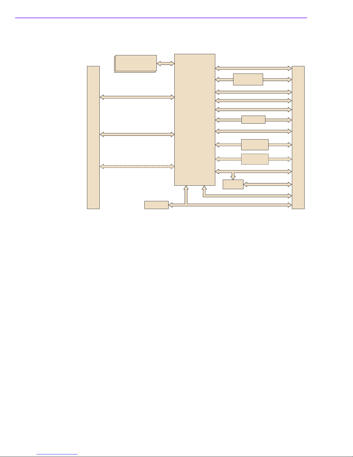
1.3 Functional Block Diagram
Figure 1.1 Functional Block Diagram
2 SATAII
3 PCIex1
(Option for 1 PCle x 4 remove LAN)
HD Audio
Analog VGA
4 USB2.0
4 USB2.0
(USB Client, option)
WDT / GPIO / I2C
SMBus
SPI Bus
LPC BUS
HSIC
1 PCIex1
DDI 2
RS1/ RS2/ FAN
Dual Channel LVDS
(LVDS BOM option)
DDR3L 1066/1333MHz
204-pin SODIMM
up to 8GB non-ECC
1 USB3.0
DDI 2 HDMI / DisplayPort / DVI
(Option BOM with LVDS)
DDI 1 HDMI / DisplayPort / DVI
iManager
SPI BIOS
USB4604
Connector Row A,B
Connector Row C,D
Intel E3845/
E3827/ J1900
Chrontel
CH7511B
PCIe-to-GbE
(Intel I210)
USB3.0 GBE
GBE
USB3.0-to-LAN
(option)

Chapter 2
2Mechanical
Information
This chapter gives mechanical
information on the SOM-6867 CPU
Computer on Module
Sections include:
Board Information
Mechanical Drawing
Assembly Drawing

SOM-6867 User Manual 6
2.1 Board Information
The figures below indicate the main chips on SOM-6867 Computer-on-Module.
Please aware on these positions while designing your carrier board to avoid mechan-
ical and thermal issues for best performance.
Figure 2.1 Board Chips Identify - Front
Figure 2.2 Board Chips Identify - Back
DDR3L SODIMM
BIOS Socket
Processor
OnModule
Smart Fan
Connector
COM Express
Connector
7 SOM-6867 User Manual
Chapter 2 Mechanical Information
2.1.1 Connector List
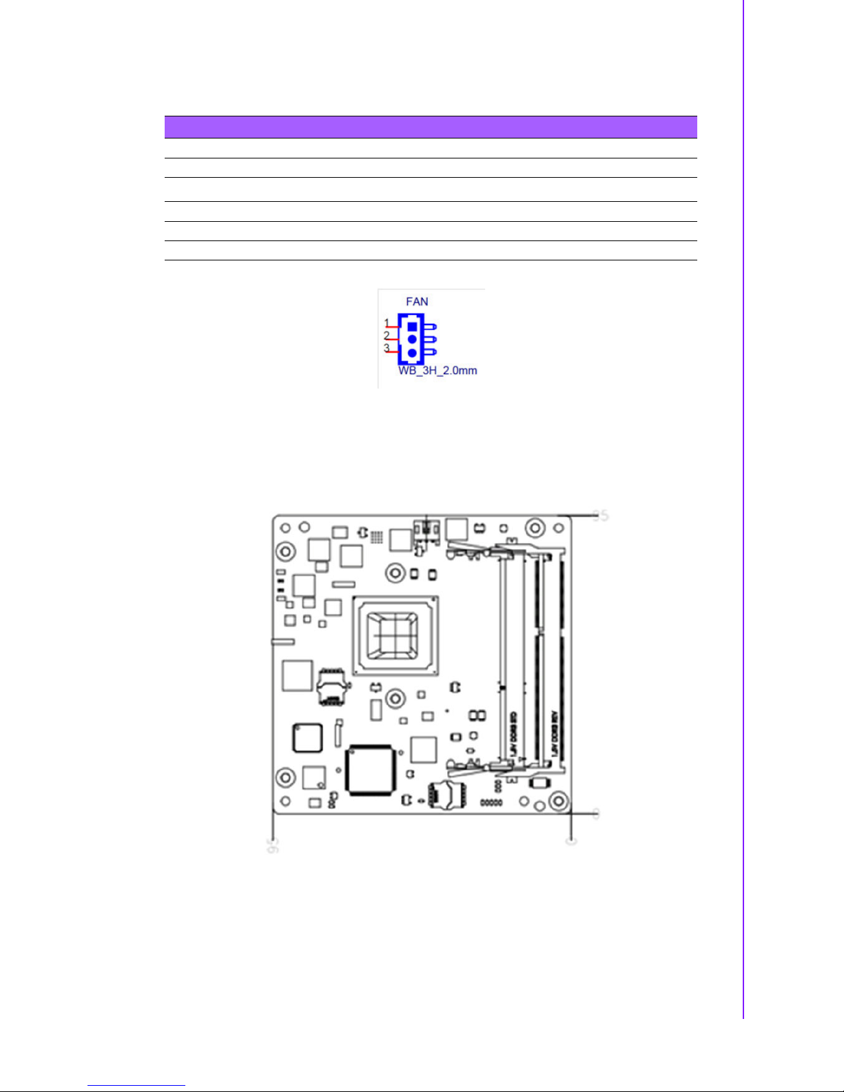
2.2 Mechanical Drawing
For more detail about 2D/3D models, please find on Advantech COM support service
website http://com.advantech.com.
Figure 2.3 Board Mechanical Drawing - Front
Table 2.1: FAN1 Fan
FAN1 Fan
Description Wafer 2.0, 3P 90D(M)DIP 2001-WR-03-LF W/Lock
Pin Pin Name
1 Fan Tacho-Input
2 Fan Out
3GND

SOM-6867 User Manual 8
Figure 2.4 Board Mechanical Drawing - Back
Figure 2.5 Board Mechanical Drawing - Back

9 SOM-6867 User Manual
Chapter 2 Mechanical Information
2.3 Assembly Drawing
These figures demonstrate the assembly order from thermal module, COM module to
carrier board.
Figure 2.6 Assembly Drawing
There are 4 reserved screw holes for SOM-6867 to be pre-assembled with heat
spreader.
Stand off
+ Nut
M2.5 Screw
Table of contents
Popular Control Unit manuals by other brands


SIGMA TEK
SIGMA TEK AI 022-1 operating manual

Delta
Delta AC-160-DIN user manual

Flow Safe
Flow Safe F7000 SERIES Installation, operation & maintenance manual

Keyautomation
Keyautomation CT102 24 quick start guide

Guard master
Guard master MINOTAUR MSR22LM quick start guide

Alfalaval
Alfalaval Unique Mixproof instruction manual

TracoPower
TracoPower TSP-BCM24 Operating instructions manual

Skytech
Skytech AFVK-SP Series troubleshooting guide

Atos
Atos DKE AC Series instructions

Technica Engineering
Technica Engineering 1000Base-T1 SPY mini user manual

protech
protech SORADIO installation instructions

ITS Telecom
ITS Telecom EKSELANS IPC 24 user manual