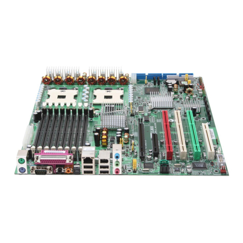
IWILL BD100 Plus User manual

1
EC Declaration of Conformity
We
Iwill Corp.
No. 10, Wu Chuan 3rd Rd.,
Hsin Chuang City, Taipei,
Taiwan, R.O.C.
Declare under sole responsibility that the
BD100 Plus motherboard
Meets the intent of Directive 89/336/ECC for Electromagnetic Compatibility. Compliance was
demonstrated to the following specifications as listed in the official Journal of the European
Communities:
EN 50081-1 Emissions:
EN 55022 Radiated, Class B
EN 55022 Conducted, Class B
EN 60555-2 Power Harmonics
EN 50082-1 Immunity:
IEC 801-2 Electrostatic Discharge
IEC 801-3 RF Radiate
IEC 801-4 Fast Transient

2
About This Manual
This manual will introduce to the user how this product is consisted. All useful information will be
described in later chapters. Keep this manual for your future upgrade or system re-configuration.
Chapter 0 Overview
An overview of some special and basic features of the BD100 Plus motherboard
Chapter 1 Features
The detailed features and specifications of the BD100 Plus motherboard
Chapter 2 Quick Installation
The quick reference for experienced users
Chapter 3 Hardware Installation
The detailed information on jumper setting, connection, and hardware installation
Chapter 4 System BIOS Setup
The detail information of the system BIOS setup options
Chapter 5 Software and Tools
The detail information for install software and tools
Copyright
This manual contains information protected by copyright law. All rights are reserved. No any part of
this document may be used or reproduced in any forms or by any means, or stored in a database or
retrieval system without prior written permission from Iwill Corp.
This manual is subject to change without notice.
Trademark
Intel / Pentium are trademarks of Intel Corporation.
IWILL and IWILL logo are trademarks of IWILL Corp.
Sound Blaster is a registered trademark of Creative Technology Ltd.
Sound Blaster-LINK and SB-LINK are trademarks of Creative Technology Ltd.
All other product names are trademarks and registered trademarks of their respective owners.
Warning
Most of the features of this product have passed strict verification and are subject to change at any
time without notice. If any malfunction occurs due to the future technical changes made by the
respective component manufacturers, Iwill assumes no responsibility or liability for it.

3
Contents
CHAPTER 0.................................................................................................5
OVERVIEW.................................................................................................5
CHAPTER 1.................................................................................................7
FEATURES...................................................................................................7
1.1 FEATURES ..............................................................................................7
1.2 ENVIRONMENT REQUIREMENTS...............................................................9
1.3 MOTHERBOARD COMPONENTS PLACEMENT...........................................10
1.4 BACK PANEL CONNECTOR ..................................................................102
1.5 FORM FACTOR......................................................................................13
CHAPTER 2...............................................................................................15
QUICK INSTALLATION..........................................................................15
CHAPTER 3...............................................................................................19
HARDWARE INSTALLATION ................................................................19
3.1 PREPARATION AND INSPECTION .............................................................19
3.2 UNPACK THE BD100 PLUS....................................................................19
3.3 INSTALLATION PROCEDURE ...................................................................20
CHAPTER 4...............................................................................................29
SYSTEM BIOS SETUP..............................................................................29
4.1 INTRODUCTION.....................................................................................29
4.2 MAIN MENU.........................................................................................30
4.3 STANDARD CMOS SETUP ...............................................................31
4.4 BIOS FEATURES SETUP...................................................................34
4.5 CHIPSET FEATURES SETUP ............................................................38
4.6 POWER MANAGEMENT SETUP......................................................41
4.7 PNP/ PCI CONFIGURATION..............................................................45

4
4.8 INTEGRATED PERIPHERALS ..........................................................46
4.9 LOAD SETUP DEFAULTS.................................................................50
4.10 IWILL SMART SETTING.................................................................50
4.11 SUPERVISOR / USER PASSWORD SETTING.................................51
4.12 IDE HDD AUTODETECTION..........................................................52
4.13 SAVE & EXIT SETUP.......................................................................52
4.14 EXIT WITHOUT SAVING................................................................52
CHAPTER 5...............................................................................................53
SOFTWARE AND TOOLS........................................................................53
5.1 SOFTWARE INSTALLATION.....................................................................53
5.2 HOW TO MAKE DRIVER DISKETTE WITHOUT O.S. INSTALLED...................54
5.3 CPU FREQUENCY SELECTION BY BIOS..................................................54
5.4 VIEW DETAILED MANUAL.....................................................................55
5.5 INSTALLING OPERATING SYSTEMS.........................................................55
5.6 INSTALLING THE SUSPEND TO DISK UTILITY ON YOUR BD100 PLUS ......57
5.7 HOW TO USE THE THERMAL SENSOR......................................................62
5.8 IWILL SCSI SERIES ...............................................................................63

5
Chapter 0
Overview
Thank you for purchasing Iwill BD100 Plus motherboard. This operation manual will instruct you
how to configure and install the system properly. It contains an overview about the engineering
design and features of this product. Also, this manual provides useful information for later upgrades
or configuration changes. Keep this for your future reference.
BD100 PLUS FEATURES
The BD100 Plus is the newest, most exciting motherboard in the market today. A step ahead of the
competition, the BD100 Plus provides more power, convenience, and reliability for users. The
BD100 Plus has more speed, and is great for better, fast computer graphics. The BD100 Plus has our
special Iwill Smart Setting—an easy way to set your CPU frequency—and also more versatile
power-on functions, all for your convenience. Furthermore, the BD100 Plus has several power
saving modes to reduce energy waste. All of these features are compacted in a dynamic motherboard
that has the stability you require in a powerful motherboard. Special features of the BD100 Plus
include:
lAGP Booster—allows for fast graphics for games, and in some cases brings more
stability to your AGP port
lIwill Smart Setting—allows easy setting of your CPU frequency, no jumpers required!
lVersatile Power-On—you can power-on the system using a hot key, password, LAN,
or modem
lPower Management Setup—allows you to set Doze, Standby, and Suspend modes
lPower Failure Recovery—after a power failure, the system will automatically turn on
again once the power returns
lHealth Monitoring System—helps manage your system so that your system runs safely
The BD100 Plus also includes some basic features, such as: 1 x Slot 1 for Pentium® III/II/Celeron,
Intel 443BX chipset, 4 x DIMM slots, 5 x PCI slots, 1 x FDC floppy disk connector, 2 x IDE
connectors, 2 x USB ports, 1 x PS/2 mouse, 1 x PS/2 keyboard ports, one parallel port, two serial
ports, ATX power connector, one Sound Blast Link connector, and much, much more!
The BD100 Plus has speed, convenience, and reliability, all wrapped up in one outstanding
motherboard. The BD100 Plus is ahead of the pack. There is no other motherboard quite like it.
Iwill: Lead the way into the 21st century!
6
YEAR 2000 issue
The IBM compatible PC utilizes a Motorola MC146818 compatible Real-Time Clock (RTC) chip to
maintain the date and time. Unfortunately, the “century”is not manipulated by the RTC. It uses 8-
bits of information to report the year and can only hold the last two digits of a year in packed BCD
format. For example, 1997 is reported solely as 97. Since the RTC also contains non-volatile
memory, IBM specified a location in the memory to hold “century”information. By combining the
century data with the year data, software can obtain a full 4-digit year. When the Year 2000 occurs,
the RTC reports the year as ’00’and the “century”in RTC memory will contain ’19.’Combining the
full 4-digit year yields 1900, not 2000. Any applications which compare dates, or uses relative dates
to perform functions will see incorrect dates.
All motherboards contain BIOS, which is one of the key ingredients to check for systems designed to
handle the year 2000. All motherboards currently shipped from Iwill contain BIOS capable of
handling the year 2000 date correctly. The BIOS contains a feature that checks the least two
significant digits of the year stored in the RTC during each BIOS request (INT 1Ah) to read the date
and, if less than `80', updates the century byte to `20'. This feature enables operating systems and
applications using the BIOS date/time services to reliably manipulate the year as a four-digit value.
Be aware that the BIOS capability alone does not ensure that the system will handle the transition
correctly. Other system components such as the operating system and application software also need
to be able to handle the year 2000 date, and recognize the date format from other sources.
Peripherals and Devices
If you want to improve your system’s I/O performance, choose the latest Iwill SCSI controllers. The
following are some Iwill SCSI controllers you may purchase and use with your BD100 Plus
motherboard:
lSIDE 2930C: a fast SCSI for MO, CD-R, CD-R/W, CD-ROM. This
value/performance SCSI card connects up to 7 devices.
lSIDE 2930U+: a 20MB/Sec. transfer rate. A full function card, supports booting from
hard disk or CD-ROM, connects 7 devices
lSIDE 2935UW: 40 MB/sec transfer rate, 15 devices. The most stable product for an
efficient system
lSIDE 2935LVD: an 80MB/sec transfer rate, and a 12-meter cable length connecting 15
devices. Perfect solution for enthusiasts.

7
Chapter 1
Features
1.1 Features
1.1.1 Processor
Supports single Pentium®
III/II/Celeron processors
Supports 100 MHz and 66 MHz bus speeds
Supports all published Pentium®
III/II/Celeron processor voltages
SEC (Single Edge Contact) cartridge Slot 1 connector
Jumper inside selects the processor speed from 233 MHz to 500 MHz or higher
1.1.2 Core Logic
Intel 82443BX PCI/ AGP controller
Integrated DRAM controller
Integrated PCI bus mastering controller
Integrated Accelerated Graphics Port (AGP) bus controller
Intel 82371EB PCI/ISA/IDE Xcelerator (PIIX4E)
Multifunction PCI-to-ISA bridge (PCI Rev 2.1 compliant)
Integrated IDE controller with Ultra DMA/33 support
USB host interface with support for two USB ports
Enhanced DMA controller and standard Interrupt controller and Timer function
System Management Bus (SMB) with support for DIMM Serial PD
1.1.3 Main Memory
4 x 168-pin DIMM (Dual Inline Memory Module) sockets
Supports up to 1 GB of 3.3 V Unbuffered SDRAM or Registered DIMM
Supports up to 1 GB of 3.3 V Extended Data Out (EDO) memory.
64-bit data interface with ECC support (SDRAM only)

8
1.1.4 Multi I/O
Winbond W83977 super I/O controller
Note: Several different chips of the W83977 series may be used to support special features.
Supports two floppy disk drives (include 3 Mode drive) and / or QIC-80 tape drive
Supports one multi-mode parallel port
Supports two high speed 16550 FIFO serial ports
Integrated keyboard controller
Integrated PS/2 mouse controller
Supports PS/2 Power-On function
Supports Power Failure Recovery
1.1.5 Expansion slots
1 x ISA slot
4 x PCI slots
1 x shared ISA/PCI slot
1 x AGP slot
1.1.6 Form Factor
Compliance with ATX Version 2.01 specification
Supports ATX power supply connector
Supports the remote on/off switch
Physical dimensions: length: 188 mm / width: 305 mm
1.1.7 Manageability
Winbond W83781 System Hardware Monitor built-in.
Note: Several different chips of the W83781 series may be used to support special features.
Wake on LAN header for use with add-in network interface cards (NICs)
Power failure recovery
Wake on modem
1.1.8 Other features
Award BIOS
Using 2Mbit Flash ROM to provide on-board-upgrade ability without changing components
Plug and Play compatible
Supports Advanced Power Management (APM)
Supports ACPI (Advanced Configuration Power Interface)
Supports Creative SB-LINK to deliver Sound Blaster 16 compatibility

9
1.2 Environment Requirements
Temperature 0-55 degrees C (operating or storage)
5% to 95% non-condensing relative humidity
At least a 250 W power supply
The power supply must comply with the following recommendations found in the specifications:
The potential relation between 3.3 VDC and +5 VDC power rails
The current capability of the +5VSB line
All timing parameters

10
1.3 Motherboard Components Placement
The following figure shows the location of the components on the BD100 Plus motherboard.
FAN1
AGP
FAN3
IDE0
IDE1
S2
S1
LPT
SLOT1
USB
MS
KB
J21,J22
JP5
PWR ON
PWR
DIMM0~3
FDC
J43
IR
1
NC
NC
VCC
IRRX
GND
IRTX
IRMODE
7
GND
+12V
SENSE
1
3
1--2:Normal
2--3:Clear CMOS
1
3
JP1
SB-LINK
GNT#
1
3
6
4
GND
REQ#
GND
SIRQ
1
1
1
1
PCIx
1
1
LID-ON
GND
5VSB
1
3
WOL
FAN2
Tmp2
1
10
11
20
RST ALED
KL
SPKR
Cathode-
Anode+
Reset
GND
VCC
Cathode-
NC
Anode+
Buzz
GND
Keylock
GND
NC
PLED
ACPI LED
Anode+ Cathode-
1
JP10
JP9
J52
JP11
JP42

11
Location Screen Printing Description
J3 Slot 1 Processor Slot 1 connector
J5--J8 DIMM0--3 168-pin DIMM Sockets
J11 AGP AGP connector
J12--J16 PCI1--5 PCI expansion slots
J21--J22 J21, J22 ISA expansion slots
J28 IDE 0 Primary IDE connector
J29 IDE 1 Secondary IDE connector
J30 FDC Floppy drive connector
J31 S1 Serial 1 connector
J32 S2 Serial 2 connector
J33 LPT Parallel connector
J34 USB Two USB connectors
J35 MS PS/2 mouse connector
J35 KB PS/2 keyboard connector
J37 PWR Standard ATX power connector
J39 FAN1 Processor fan header
J40 FAN2 System fan header
J41 FAN3 System fan header
J42 PWR ON Remote power-on/off header
J43 J43 Front panel I/O header
ACPI LED (pins 1--2): ACPI LED header
ALED (pins 5--6): IDE LED header
RST (pins 9--10): Reset Switch header
PLED (pins 11--13): Power LED header
KL (pins 14--15): Keylock switch header
SPKR (pins 17--20): Speaker header
J44 SB-LINK Creative SB-LINK header
J45 IR IR (infrared) connector
J46 WOL Wake On LAN header
J50 Tmp2 2nd temperature sensor header
J52 KB ON PS/2 Power-On jumper block
JP1 CLRTC Jumper for clearing CMOS
JP5 JP5 Jumper for PCI devices compatibility
JP9 JP9 Adjustable Vcore (5% or 10 %)
JP10 VIO Adjustable VIO (3.5, 3.6, or 3.8)
JP11 JP11 Adjustable AGP Frequency
JP42 JP42 Clear Keyboard Power-On Password

12
1.4 Back Panel Connectors
The following figure shows the location of the back panel I/O connectors, which include:
PS/2-style keyboard and mouse connectors
Two USB connectors
Two serial port connectors
One parallel port connector
Serial 1
Mouse
Keyboard
Parallel
Serial 2
USB1
USB0

13
1.5 Form Factor
The BD100 Plus motherboard is designed to fit into an ATX form-factor chassis. The I/O connector
locations and the mounting hole locations are in compliance with the ATX specification. Please see
details in the following figure:
Datum (0, 0)
A
B
C
D
E
F
G
6.250
REAR I/O WINDOW IN CHASSIS
0.156 inch
Mounting Holes
H
I
J
K
L
0.800 TYP.
Between
Connectors 1.612 Pin 1 ISA
to Pin 1 PCI 0.768 Pin 1 AGP
to Pin 1 PCI
A: 0.400 inch H: 0.150 inch
B: 1.000 inch I: 0.650 inch
C: 1.300 inch J: 5.550 inch
D: 1.625 inch K: 11.750 inch
E: 2.627 inch L: 12.000 inch
F: 6.500 inch
G: 7.086 inch

14

15
Chapter 2
Quick Installation
Several easy installation steps will be described in this chapter to help the experienced users with
quick installation. If you are a beginner, or need to know more about this product, please refer to
Chapter 3.
Note: Please reviews 1.3 Motherboard Components Placement graphic for reference.
Warning: Users must follow these guidelines to ensure the BD100 Plus is protected during
installation.
a. Make sure your computer is unplugged whenever working with inside components.
b. Beware of Static electricity! Either wear anti-static wrist straps, or ensure that you
touch a safely grounded object (such as a metal desk/table). Don’t handle components
near high static objects (i.e. carpets, wool/ acrylic sweaters, etc.).
c. Pick up components by their bodies. Try not to touch IC chips, connectors or leads.
Don’t handle components any more than necessary.
d. Keep all magnets away from both your hard and floppy disk drives, especially magnetic
screwdrivers. Keep both floppy and hard disks apart if disassembled.
e. Keep water and liquids away from your computer and its components.
Step 1. Install processor
This process is for motherboards already equipped with the universal retention mechanism.
For Pentium II processors:
a. Lift each of the two retention mechanism brackets so that they stand fully upright.
You should hear a soft “click”sound once each bracket is in the correct upright
position.
b. With the CPU fan facing the DIMM sockets, insert the CPU horizontally into the
retention mechanism, sliding both edges in simultaneously and as “evenly”as
possible. Then, press down gently yet firmly so that the CPU is fully inserted
correctly into the socket.
c. Locate the two CPU lock switches, which are on the top, one on each side of the
CPU just above its respective bracket. With the CPU fan facing you, use both
hands and grasp the CPU, placing each thumb on top of each lock switch. Then,
at the same time “flip”each lock switch outward in opposite directions (both
away from the CPU fan). You should hear two “click”sounds, one from each
switch. This indicates the CPU is secured into place.
d. To release CPU, grasp the CPU (in the same manner in “c”above) and push both
lock switches inward (toward the CPU fan). You should hear two “click”sounds,
one from each switch. Lift CPU upward and out of the socket.

16
For Pentium III/Celeron processors:
a. Follow steps “a”~ “b”above.
b. Locate the two sliding locks on each bracket. Read the writing on each lock:
“OPEN”and “LOCK”. To lock, use your index finger and thumb, grasp each
lock, and gently slide upward. This may be done simultaneously with two hands,
or one at a time. Once each lock has been fixed upward, the CPU is secured into
place.
c. To release CPU, use your index finger and thumb, grasp each lock, and gently
push downward. Lift the CPU upward and out of the socket.
Step 2. Install processor fan
This process is executed more quickly if your Pentium II/III/Celeron processor already has a fan
attached to it. If so, attach the processor fan power cable to the “FAN1”header.
Step 3. Setting CPU speed
The CPU speed is setup using Iwill Smart Setting. This is found in the BIOS setup by pressing
<Del> during the boot up process. Please refer to Chapter 4 for instructions on setting CPU speed.
Note: The CPU speed must be setup according to the CPU’s specifications.
Step 4. Install the memory module
At least one memory module, such as a 168-pin 3.3V unbuffered SDRAM, Registered DIMM or
EDO DIMM, needs to be inserted into the DIMM sockets. You may select any of the four DIMM
sockets—there are no restrictions.
Note: Be sure the edges of your memory module line-up correctly with the socket before attempting
to insert the memory module.
Step 5. Connect the internal peripherals
The internal peripherals are devices that are located within the computer chassis, such as the floppy
disk drive, hard disk drive, CD-ROM drive, etc. There is one 34-pin flat cable for floppy disk drive,
and one 40-pin flat cable for several IDE devices included in your retail package.
Note: The plastic lead on the middle of one side of the cable’s connector acts as a key, and slides
easily into the gap in the middle of the receiving connector on the motherboard when inserting the
cable connector.
Step 6. Connect the Reset button
The 2-pin reset header is located on pins 9--10 (identified as RST). Connect the reset button cable
from the RST header to the reset button on the front panel of your PC case.
Locate the RST header on the motherboard:
Pin 9 RESET
Pin 10 Ground
1
11
1
2

17
Step 7. Connect the Speaker
The 4-pin speaker header is located on pins 17--20 (identified as SPKR. Connect the cable from the
SPKR header to the speaker on the front panel of your PC case.
Locate the SPKR header on the motherboard:
Pin 17 VCC
Pin 18 Ground
Pin 19 NC
Pin 20 BUZZ
Step 8. Connect the power LED
The 3-pin power LED header is located on pins 11--13 (identified as PLED. Connect the cable from
the PLED header to the power LED on the front panel of your PC case.
Locate the PLED header on the motherboard:
Pin 11 Anode (+)
Pin 12 NC
Pin 13 Cathode (-)
Step 9. Connect the keylock switch
The 2-pin keylock header is located on pins 14--15 (identified as KL). Connect the cable from the
KL header to the keylock switch (if supported) on the front panel of your PC case.
Locate the KL header on the motherboard:
Pin 14 KEYLOCK
Pin 15 Ground
Step 10. Connect the IDE LED
The 2-pin IDE LED header is located on pins 5--6 (identified as ALED). Connect the cable from
ALED header to the LED on the front panel of your PC case.
Locate the ALED header on the motherboard:
Pin 5 Anode (+)
Pin 6 Cathode (-)
Step 11. Connect the ACPI LED
The 2-pin ACPI LED is located on pins 1-2 (marked as ACPI) of the front panel connector. Connect
the chassis‘s ACPI LED to this header.
Signal of ACPI LED header
Pin 1 Cathode (-)
Pin 2 Anode (+)
1
11
1
2
1
11
1
2
1
11
1
2
1
11
1
2
1
11
1
2

18
Step 12. Connect the Power-ON button
All ATX computers provide a Power-On button on the front panel of your PC case. Simply plug in
the ATX power connector into the Power-On button.
Step 13. Install the Power Supply cord
The BD100 Plus motherboard provides a 20-pin ATX power connector. This works in conjunction
with the Power-On button to provide remote On/Off function.
Step 14. Install the Keyboard
Connect the cable from the PS/2 keyboard connector at the back panel to the keyboard.
Step 15. Install the Display Card
Insert the display card into the ISA, PCI or AGP expansion slot.
Step 16. Connect the External Peripherals
The external peripherals are devices located outside the computer chassis, such as the serial mouse,
printer, PS/2 mouse, external modem, etc. Connect these devices to their appropriate connectors.
Step 17. Power-on the system
Once the system is powered on, make sure you enter the BIOS setup program and load the
manufacturer’s default settings. After the system reboot, you are ready to install your operating
system. Enjoy!

19
Chapter 3
Hardware Installation
3.1 Preparation and Inspection
The BD100 Plus motherboard, like all other electronic equipment, is sensitive to static. Please take
the proper precautions when handling it. If possible, ground yourself by touching a metal table or
desk. Keep the board in its conductive wrapping until it is configured and ready to be installed in
your system.
Note: Please review 1.3 Motherboard Components Placement graphic for reference.
3.2 Unpack the BD100 Plus
You should find the following components when opening the box:
One BD100 Plus motherboard
This operation manual
One 40-pin IDE cable
One 34-pin floppy cable
One Iwill Power Installer CD diskette
One Thermal Sensor Kit)
For installation, you may need some or all of the following tools:
Medium size flat blade screwdriver
Medium size Phillips head screwdriver
A 3/16 inch nut driver or wrench
Warning: Users must follow these guidelines to ensure the BD100 Plus is protected during
installation.
a. Make sure your computer is unplugged whenever working with inside components.
b. Beware of Static electricity! Either wear anti-static wrist straps, or ensure that you
touch a safely grounded object (such as a metal desk/table). Don’t handle components
near high static objects (i.e. carpets, wool/ acrylic sweaters, etc.).
c. Pick up components by their bodies. Try not to touch IC chips, connectors or leads.
Don’t handle components any more than necessary.
d. Keep all magnets away from both your hard and floppy disk drives, especially magnetic
screwdrivers. Keep both floppy and hard disks apart if disassembled.
e. Keep water and liquids away from your computer and its components.

20
3.3 Installation procedure
3.3.1 Processor (Slot 1 and FAN1)
The BD100 Plus motherboard supports single Pentium®
III/II/Celeron processors. The processor’s
VID pins automatically program the voltage regulator on the motherboard to the required voltage.
The motherboard currently supports processors that run internally from 233 MHz to 500 MHz or
higher.
This process is for motherboards already equipped with the universal retention mechanism.
For Pentium II processors:
a. Lift each of the two retention mechanism brackets so that they stand fully upright.
You should hear a soft “click”sound once each bracket is in the correct upright
position.
b. With the CPU fan facing the DIMM sockets, insert the CPU horizontally into the
retention mechanism, sliding both edges in simultaneously and as “evenly”as
possible. Then, press down gently yet firmly so that the CPU is fully inserted
correctly into the socket.
c. Locate the two CPU lock switches, which are on the top, one on each side of the
CPU just above its respective bracket. With the CPU fan facing you, use both hands
and grasp the CPU, placing each thumb on top of each lock switch. Then, at the
same time “flip”each lock switch outward in opposite directions (both away from
the CPU fan). You should hear two “click”sounds, one from each switch. This
indicates the CPU is secured into place.
d. To release CPU, grasp the CPU (in the same manner in “c”above) and push both
lock switches inward (toward the CPU fan). You should hear two “click”sounds,
one from each switch. Lift CPU upward and out of the socket.
For Pentium III/Celeron processors:
a. Follow steps “a”~ “b”above.
b. Locate the two sliding locks on each bracket. Read the writing on each lock:
“OPEN”and “LOCK”. To lock, use your index finger and thumb, grasp each lock,
and gently slide upward. This may be done simultaneously with two hands, or one
at a time. Once each lock has been fixed upward, the CPU is secured into place.
c. To release CPU, use your index finger and thumb, grasp each lock, and gently push
downward. Lift the CPU upward and out of the socket.
Locate the FAN1 header (processor fan header) on the motherboard:
Pin 1 Ground
Pin 2 +12 V
Pin 3 SENSE
Note 1. The processor fan must always be attached to the processor to prevent overheating.
Note 2. The second-level cache is located on the base of the SEC cartridge. The cache size and
cacheable memory size vary, depending on the processor used.
Table of contents
Other IWILL Motherboard manuals

IWILL
IWILL K7S2 Series User manual

IWILL
IWILL P6NS User manual

IWILL
IWILL FB24624100 User manual

IWILL
IWILL P4R533 User manual

IWILL
IWILL LE370 User manual

IWILL
IWILL P4G Series User manual

IWILL
IWILL DP533 Series User manual

IWILL
IWILL DK8X User manual

IWILL
IWILL WO2 Original operating instructions

IWILL
IWILL DVD266 User manual

IWILL
IWILL DP6NS User manual

IWILL
IWILL KK266Plus User manual

IWILL
IWILL P4E Series User manual

IWILL
IWILL KK266 User manual

IWILL
IWILL VD133 Pro Series User manual

IWILL
IWILL Motherboard DJ800 User manual

IWILL
IWILL Motherboard DJ800 User manual

IWILL
IWILL KK266 User manual

IWILL
IWILL dca200 User manual

IWILL
IWILL DX400-SN User manual