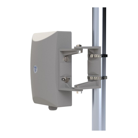
FORTEZA FM-30(24)-C-BT User manual

FORTEZA JSC FORTEZA FM-30(24)-BT
Please visit our internet sites: www.forteza.com or www.forteza.eu Page 2
TABLE OF CONTENTS
1 Introduction 3
2 Purpose 4
3 Specifications 4
4 Sensor components 5
5 Operation 6
5.1Principle of operation 6
6 Sensor construction 6
7 Safety measures 10
8 Mounting 10
8.1Requirements for the protected site 10
8.2Requirements for the protected building 11
8.3Mounting on the perimeter site 11
8.4Mounting on the wall 14
9 Preparation for the operation 14
10 Adjustment with a PC 17
11Adjustment with Bluetooth 30
12 Maintenance 38
13 Troubleshooting guide 39
14 Storage 40
15 Transportation 40
16 Acceptance certificate 40
17 Warranty 40

FORTEZA JSC FORTEZA FM-30(24)-BT
Please visit our internet sites: www.forteza.com or www.forteza.eu Page 3
1...INTRODUCTION
The user manual contains the following information about the microwave monostatic
security sensor FM-30(24)-C-BT, FM-30(24)-F, FM-30(24)-V-BT:
- Purpose and principle of operation
- Sensor components and possible delivery sets
- Sensor specifications and its components
- Operating and servicing rules
There is the information about tare, packaging and conditions of the sensor transportation.
This document contains the required information for the correct operation, maintenance and
storage of the sensor.
The manufacturer constantly improves the sensor and reserves the right to make changes to
their constructions, which do not worsen the sensor specifications.

FORTEZA JSC FORTEZA FM-30(24)-BT
Please visit our internet sites: www.forteza.com or www.forteza.eu Page 4
2 PURPOSE
2.1 The purpose of the sensor is to protect perimeter sites, open and closed grounds of
different objects and to detect an intruder moving upright or bent in the detection zone.
Application of the sensor on objects with a high electromagnetic radiation is to check by the
trial operation.
2.2 The sensor operates continuously round-the-clock at an ambient temperature from -40 C
up to +80 С and relative humidity up to 98% at the temperature +35С.
The sensor can be adjusted via Bluetooth at the ambient temperature from -25 C up to +75 С.
The industrial version, the placement category not more than 1 (for outdoor operation)
according to the state standard GOST 15150-69. The enclosure protection degree is IP55
according to the state standard GOST 14254-96.
2.3 The distinctive feature of the sensor is that the detection zone consists of 12 sub-zones.
Each sub-zone can be adjusted using a PC via USB-interface (disconnection of sub-zones,
separately sensitivity setting in each sub-zone and etc.), remotely via the interface RS-485 or
with an Android-Device via the wireless interface Bluetooth.
3 SPECIFICATIONS
3.1 The operation frequencies range is 24,05…24,25 GHz.
3.2 The maximum detection zone length is 30 m (12 cross-cut subzones of 2,5 m).
The detection zone is a volumetric part of the protected site, where any intruder movement
generates an alarm.
The sensor can be produced with one of five frequency letters L1, L2, L3, L4 and L5 to
eliminate interferences when some sets are used next to each other. Please specify the
frequency letters when ordering.
The detection zone parameters are given in Table 3.1
Table 3.1
Characteristic
Modification
FM-30(24)-V-BT
FM-30(24)-C-BT
FM-30(24)-F-BT
Width, m
12
2
40
Height, m
8
40
2
3.3 The detection zone length can be regulated from 2,5 m up to 30 m.
3.4 The sensor generates an alarm when:
- an intruder (moving at his “full height” or ”bent”) crosses the detection zone at a speed
from 0,3 up to 8 m/sec with the minimum detection probability 0,98;

FORTEZA JSC FORTEZA FM-30(24)-BT
Please visit our internet sites: www.forteza.com or www.forteza.eu Page 5
- the absence of supply voltage.
The alarm is generated by breaking the actuating optoelectronic relay contacts for 3 sec
minimum. This signal is transmitted by the yellow and pink wires.
3.5 The characteristics of the actuating optoelectronic relay are: the maximum switching
current is 0,1 A; the maximum voltage is 50 V; the maximum resistance is 130 Ohm in the
closed condition (with the lightning guard elements).
3.6 The sensor generates an alarm at the opening of the cover, under which there are
adjusters. The contacts of the blocking button are open at the cover opening. This alarm is
transmitted by blue and grey wires. Operating characteristics of the blocking contacts: the
current is up to 0,2 A at the voltage up to 80 V.
3.7 The recovery time of the standby mode after an alarm is up to 5 sec.
3.8 The time of the technical availability after the supply voltage signal is up to 15 sec.
3.9 The sensor power supply: from 10 up to 30 VDC with the maximum pulsation of 0,03 V.
The maximum power consumption is 1,5 W.
3.10 The sensor has the automatic and remote control.
3.11 The sensor doesn’t generate an alarm at:
- rain, snow, fog;
- solar radiation;
- wind speed up to 20 m/sec;
- birds and small animals in the detection zone with the linear dimensions up to 0,3 m;
- irregularities up to + 0,3 m on the protected site;
- snow cover up to 0,3m (without additional adjustment);
- grass up to 0,2 m;
- influence of ultra short waves emissions of the range 433 MHz and mobile phones at
the distance more than 0,5 m from the sensor.
3.12 The sensor is immune to electromagnetic interferences according to GOST R 50009-
2000 (voltage impulses in supply circuits, breaks of mains supply, electrostatic discharges
and electromagnetic fields).
3.13 Input circuits of the sensor are protected from electric pickup (including electric
storms).
3.14 The sensor mean lifetime is 8 years.
3.15 The mean time between failures is 60000 hours.
3.16 Maximum dimensions of the units without a mounting kit, mm: 141х123х67.
3.17 Maximum weight, kg: 0,4.
4 SENSOR COMPONENTS
4.1 The sensor delivery set:
- transceiver –1 pc

FORTEZA JSC FORTEZA FM-30(24)-BT
Please visit our internet sites: www.forteza.com or www.forteza.eu Page 6
- mounting kit on a support (MK-1):
- bracket –1 pc
- buckle –2 pcs
- key S8x10 –1 pc
- protective visor and 2 self-tapping screws 3,9x19 to fasten it
- user manual –1 pc
- package
4.2 The following components can be supplied by order:
- USB cable A-B for connection with a PC
- interface converter RS485 (RS485-Com, RS485-USB)
- software*
- mounting kit for mounting on the wall (BRACKET-120, BRACKET-350, BRACKET-500)
- power supply unit PSU-U-15-0,15
- junction box JB-15 or JB-30
- SUPPORT-2 (SUPPORT-2,5, SUPPORT-3, SUPPORT-3,5)
*The software you can download on our website www.forteza-eu.com.
5 OPERATION
5.1 Principle of operation.
The principle of operation is based on the method of linear frequency modulation, where the
generator operating frequency is changed linearly within small range. The super-high-
frequency transmitter of the transceiver unit radiates electromagnetic oscillations in the
direction of the protected area. The electromagnetic oscillations are reflected from the goal
and surrounding objects, and get to the super-high-frequency receiver of the transceiver unit.
When an intruder moves in the detection zone, the changes in the received signal caused by
the Doppler Effect are intensified and processed according to the algorithm. If these changes
exceed the threshold value, the sensor generates an alarm.
The method of linear frequency modulation and 12 cross-cut subzones increase the sensor
interference immunity and the mean time to failure.
6 SENSOR CONSTRUCTION
6.1 The sensor construction and its installation on the support are given in Fig.6.1. The
sensor construction is the following: the monoblock placed in the dust- and splashproof
enclosure. The bearing structure is base 4. On base 4 there are the microstrip antenna and the
signal processing board, protected with the radio transparent cover 5. There are two bores in
the lower part of cover 5 to prevent condensation inside the unit. It is necessary to take off

FORTEZA JSC FORTEZA FM-30(24)-BT
Please visit our internet sites: www.forteza.com or www.forteza.eu Page 7
the cover 6 to get the access to the adjustment and indication elements. The sensor is
connected to the receiving-control device with cable 8 stretched through cable gland14 and
corrugated pipe 7.
6.2 The transceiver unit is mounted on support 1 with bracket and buckles 13 as shown in
fig. 6.1. If you use some supports of the diameter more than 90 mm, apply the buckles with a
bigger diameter (width of 12 mm max). The mounting kit ST-1 provides the unit turn on
horizontal plane for 360 º, on vertical plane: up -15º minimum, down - 40º minimum.
6.3 The transceiver unit is mounted on a vertical plane (wall, fence, etc.) with the bracket:
bracket 2 as shown in fig.6.2 or 6.3. The rotation angles on the bracket on a horizontal plane
are 180º, on a vertical plane: up - 17º, down - 45º. There are 3 types of the bracket: indented
from a wall at the distance of 120 mm, 350 mm and 500 mm. The type of the bracket
depends on the sensor application.
6.4 The transceiver unit is mounted along the wall and other long surfaces with the brackets
installed at 350 mm from the wall. It is necessary to do it because of absorption and
reflection from the wall the sensor technical characteristics can worsen.

FORTEZA JSC FORTEZA FM-30(24)-BT
Please visit our internet sites: www.forteza.com or www.forteza.eu Page 8
1- support -1 pc 8- cable -1 pc
2- bracket -1 pc 9- bolt M6x35 -1 pc
3- bushing -1 pc 10- nut M6 -1 pc
4- base -1 pc 11- washer 6 -2 pcs
5- case -1 pc 12- bolt M6x35 -1 pc
6- cover -1 pc 13- buckle -2 pcs

FORTEZA JSC FORTEZA FM-30(24)-BT
Please visit our internet sites: www.forteza.com or www.forteza.eu Page 9
7- corrugated pipe -1 pc 14- cable gland -2 pcs
..... 15- protective visor -1 pc
Fig. 6.1 Mounting on a support
1- fence -1 pc 7- bolt М6х35 1 pc
2- bracket -1 pc 8- ring 1 pc
3- figured washer -2 pcs 9- nut М6 2 pcs
4- bracket fastener -1 pc 10- washer 6 4 pcs
5- Rx -1 pc 11- bolt М6х14 1 pc
6- screw М6х50 -4 pcs
Fig. 6.2 Mounting on a wall using BRACKET-350 or BRACKET-500
Note. Dear user! Manufacturer of the sensor FM-30(24) constantly upgrades its quality and
reliability. That’s why in some lots of sensors there can be design modifications unspecified
in the documents delivered with the sensors. Nevertheless, the main specifications are valid.

FORTEZA JSC FORTEZA FM-30(24)-BT
Please visit our internet sites: www.forteza.com or www.forteza.eu Page 10
7 SAFETY MEASURES
7.1 The current safety standards for the operation with electrical facilities with the voltage up
to1000 V should be observed during mounting, preventive maintenance and repair of the
sensor.
7.2 Cables should be laid, terminated and connected to the sockets only when the supply
voltage is OFF.
7.3 The power of the super high frequency energy, beaming by the sensor satisfies the
security standards and doesn’t have deleterious effect on human health.
7.4 It is prohibited to mount and maintain the sensor at thunderstorms.
7.5 Installation and maintenance of the sensor should be performed only by people, who
underwent special safety trainings.
7.6 The breach of requirements of this user manual can provoke the sensor breakdown.
8 MOUNTING
8.1 Requirements to the protected area.
The choice of the place and the correct sensor mounting on the protected sector or in
the protected room are the basic factors, which provide its operational reliability.
Please use the protective visor if using the sensor outdoor. Fasten the visor on the case of
the sensor with two screws 3,9x19 containing in the delivery kit as shown in Fig. 6.1.
The input cable should be threaded through the corrugated pipe. If you use a junction
box, insert a cable gland in it and connect the corrugated pipe to the cable gland.
The protected site should meet the following requirements:
a) height of irregularities should not exceed ±0,3m.Otherwise the characteristics of the
sensor can worsen and the application of the sensor is determined by the trial operation
b) the protected site is to clear of high grass (if higher than 0,5 m), bushes and tree branches
at the distance of 5 m minimum from the detection zone border
c) big objects moving under wind (wings of a gate, tumbledown fences, etc.) should not be
located in the detection zone and out of the detection zone at the distance of 10 m minimum
d) the grass height should not exceed 0,2 m
e) the snow height should not exceed 0,3 m
f) movement of people and animals are not permitted at the distance 5…10 m minimum from
the detection zone borders
g) to eliminate movements of people and animals in the detection zone, it is recommended to
enclose the detection zone with a fence (from 1 m height)
h) roof runoff should not be near the sensor enclosure at sensor installation on an outside
wall.

FORTEZA JSC FORTEZA FM-30(24)-BT
Please visit our internet sites: www.forteza.com or www.forteza.eu Page 11
8.2 Requirements for the protected building.
a) sensors should not be mounted on walls subjected to constant vibrations
b) animals, birds, vibrating or moving objects (vent lights, doors, air-exhausters, etc.) should
not be in the protected room.
8.3 Mounting on the perimeter site.
8.3.1. For supports it is recommended to use metal or asbestos-cement tube of 70…90 mm
diameter (the best solutions are SUPPORT-2 produced by OOO Okhrannaya technika). For
hard soils (argil, stone, etc.), the support should not be concreted and embedded in the soil of
600…800 mm. For light soils (sand, etc.) the concrete mat for the support should be 200 mm
depth and 500 mm diameter. In snowy regions (more than 1 m height), the support
superstructure should not be less than 1500 mm (it is recommended to use the device
SUPPORT-2,5 produced by OOO Okhrannaya technika). In not snowy regions the support
superstructure should be up to 1300 mm. If the sensor is used to block the upper part of the
fence, it is recommended to weld or to gear together the support and the fence for firmness.
In this case the support should be situated above the fence at 300 mm minimum.
8.3.2 Lay the main cables according to the project of the security system. It is recommended
to use cables with the core screen or metal sheath. The cables laying may be performed in the
ground or on the fence.
8.3.3 The mounting height is 1,0±0,2 m as shown in fig.6.1. To install the sensor on the
round support, the mounting kit MK-1 is used. Install the bracket 2 on the support 1 with
buckles 13.
8.3.4 Install the transceiver unit with bolt 9 (drainage bores downward) on the bracket. The
bracket should be pointed on the support so that the cover surface of the sensor is directed to
the protected area.
8.3.5. Fix the sensor at a horizontal position (relative to the ground). The model of the
detection zone form and its dimensions are shown in fig. 8.1, 8.2, 8.3 for modifications
Volume, Curtain, Fan. Under the figures is given the numeration of the subzones from 1 to
12.

FORTEZA JSC FORTEZA FM-30(24)-BT
Please visit our internet sites: www.forteza.com or www.forteza.eu Page 14
The dimensions and the detection zone configurations are given for the ideal conditions of
the perimeter area without taking into account the ambient conditions. Practically the
dimensions and the detection zone configurations can differ from the given ones because of
ambient objects, reflecting surfaces and the detection sensitivity.
8.3.6 Take into account that the signal level reflecting from a moving intruder depends on his
visibility (the reflection square). So, for example, the sensor watching from above the
intruder’s movement will be generate an alarm less than the same sensor watching in front or
side -on. That’s why during the sensor installation when the angle between the detection
zone axis and the ground surface is ≥ 45˚, the signal level can be reduced when the intruder
moves in the detection zone. To detect this intruder more exactly, it is necessary to reduce
the operation threshold; it provides the interference decrease.
8.4 Mounting on the wall.
8.4.1 Make the marking in the chosen place as shown in fig.6.2. Fix bracket 2 with screws 6
on wall 1 (3 types of the bracket: indented from a wall at the distance of 120 mm, 350 mm
and 500 mm). Insert the bolt 11 in the slot of ring 8 and fasten the transceiver unit on bracket
2. Loosen nut 9 and point the unit on the necessary direction turning it in a horizontal
surface. Tighten nut 9. Moving the transceiver in a vertical surface relative to ring slot 8,
align the unit in a vertical surface and tighten it with bolt 11.
8.4.2 The sensor can be performed in one of 5 frequency letters L1, L2, L3, L4 and L5 to
eliminate the mutual influence.
ATTENTION!
1. IT IS PROHIBITED TO INSTALL THE SENSORS HAVIG THE SAME
FREQUENCY LETTERS NEXT TO EACH OTHER. Please take into account the
project documents when ordering the sensors with different frequency letters. When
using more than 5 sensors on the object, the application is to prove by trial operation.
2. If the installation method differs from ones given in this User Manual, so the
application is to prove by trial operation.
9 PREPARATIONS FOR THE OPERATION
9.1 Preparation for the operation
9.1.1 Install the sensor according to the item 8 and connect supply and output circuits of the
sensor according to the color marking of cables as shown in Table 9.1.

FORTEZA JSC FORTEZA FM-30(24)-BT
Please visit our internet sites: www.forteza.com or www.forteza.eu Page 15
Table 9.1
Cable color
Purpose
white
Supply plus (+)
brown
Supply minus (-)
yellow
Relay contacts
pink
purple
Tamper circuit (TAMPER)
black
green
Remote control (RC)
blue
RS-485 «B»
red
RS-485 «A»
grey
Bluetooth activation
To activate the Remote Control energize the green RC wire of the output cable with voltage
from 10 up to 30 VDC for 1 sec.
The scheme of the sensor connection using the lightning guard unit «LGU-4» and the power
supply unit «PSU-U-15-0,15» is shown in fig. 9.1.

FORTEZA JSC FORTEZA FM-30(24)-BT
Please visit our internet sites: www.forteza.com or www.forteza.eu Page 16
Fig. 9.1 Connection diagram using LGU-4
The micro switch positions and the detection zone length are given in Table 9.2.
Table 9.2
Subzone number
Subzone range from the sensor
1
0-2,5 m
2
2,5-5 m
3
5-7,5 m
4
7,5-10 m
5
10-12,5 m
6
12,5-15 m
7
15-17,5 m
8
17,5-20 m
9
20-22,5 m
10
22,5-25 m
11
25-27,5 m

FORTEZA JSC FORTEZA FM-30(24)-BT
Please visit our internet sites: www.forteza.com or www.forteza.eu Page 17
12
27,5-30 m
9.2 The DETECTION ZONE LIMITATION or the “APPROVED PASSAGES”, i.e. the
subzone disconnection is performed with a PC.
If the corresponding subzone is switched OFF, the sensor does not generate an alarm if
the detection zone is crossed in this place.
CAUTION!
Avoid the adjustment of very high sensitivity to eliminate false alarms!
To reduce the quantity of false alarms, switch ON the subzones which are necessary for
its application.
10 ADJUSTMENT WITH A PC
10.1 The sensor can be adjusted with a PC. It provides an opportunity to form a complex
detection zone, set complex sensitivity and visually assess the level of noise and signal.
The sensor connection with a PC is realized with standard connective cable USB A-USB B.
To control the sensor with a computer, it is necessary to set up the software, which includes
2 stages: virtual COM-port installation and sensor control program installation.
10.2 COM-port installation
Put the disc (of the delivery kit) in the computer. Connect the sensor to the computer with
the USB cable. Apply power to the sensor. The computer will identify the type of the USB
device and will ask to install the driver. For that follow the fig. 10.1-10.4.

FORTEZA JSC FORTEZA FM-30(24)-BT
Please visit our internet sites: www.forteza.com or www.forteza.eu Page 20
After COM-PORT installation it is necessary to know its number. Please follow: START
→OPTIONS →CONTROL PANEL→SYSTEM→DEVICE→DEVICES
MANAGER→PORT (COM and LPT) →USB SERIAL PORT and remember the number.
10.3 Sensor Control Program installation
To install the program please start ConfigMaster_setup.exe.
After the file ConfigMaster_setup.exe has been started it will appear the following window
Fig. 10.5
This manual suits for next models
2
Table of contents
Other FORTEZA Security Sensor manuals
Popular Security Sensor manuals by other brands
Spectrex
Spectrex SharpEye 40/40C Series Reference manual
Saferhomee
Saferhomee HB-T001Q3 user manual
Larson Electronics
Larson Electronics EXP-EMG-EXT series instruction manual
DMP Electronics
DMP Electronics 1183-135F installation guide
FTLAB
FTLAB Radon Eye RD200 quick guide

General
General NGD269 user manual

elsner elektronik
elsner elektronik Mini-Sewi KNX L-Pr Installation and adjustment manual

Tynetec
Tynetec ZXT475 manual
SATION
SATION SS3001.1 Technical manual

Bosch
Bosch ISP-SM90-120 instruction manual

Stanley
Stanley LD200 manual
Hochiki America Corporation
Hochiki America Corporation SPC-24 INSTALLATION PROCEDURE


