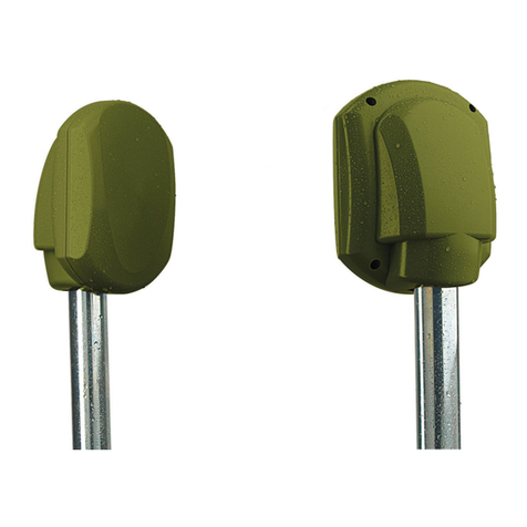
FORTEZA FMC 24 Pro Operating and installation instructions

FORTEZA JSC FORTEZA FMC 24 Pro (100m, 200m, 300m)
Please visit our internet sites: www.forteza.com or www.forteza.eu Page 2
1.DESCRIPTION AND OPERATION
The present description manual and service instruction contains information about the
operation of the microwave perimeter protection detectors series FMC 24 Pro (100m.,
200m., 300m.) below the detector. In this document there is information required for the
correct operation (use, transportation, storage and maintenance) of the detector.
The following abbreviations are used in the present document:
Tx - transmitter
Rx - receiver.
MK - mounting kit; 1.1. Purpose
1.1.1. The purpose of the sensors is to protect the perimeter sectors and to detect an
intruder crossing this sector at his “full height” or “bent”. An alarm is generated by
breaking the individual point relay contacts. Then it is transmitted on the receiver.
1.1.2. The detector is intended for continuous round-the-clock outdoor operation at an
ambient temperature -40ºC…+60С and relative humidity up to 98% at the temperature
+35С.
1.1.3. When the sensor operates with the alarm complex, you can control the sensor
with RS-485 interface. 1.2. Specifications
1.2.1. The recommended length (L) of a sector for modifications:
FMC 24 Pro (300m) –10…300 m
FMC 24 Pro (200m) –10…200 m
FMC 24 Pro (100m) –10…100 m
The detection zone height, h:
FMC 24 Pro (300m) 1,8 m* maximum
FMC 24 Pro (200m) 1,8 m* maximum
FMC 24 Pro (100m) 1,6 m* maximum
The detection zone width, b :
FMC 24 Pro (300m) 2,1 m* maximum
FMC 24 Pro (200m) 1,9 m* maximum
FMC 24 Pro (100m) 1,5 m* maximum
* in the middle of a sector at the maximum length
The cross speed: 0,1 up to 8 m/sec
The quantity of the frequency channels 8
Supply voltage 9…30 V
Current consumption to 190 mA (12 V DC)
-Tx 79 mA

FORTEZA JSC FORTEZA FMC 24 Pro (100m, 200m, 300m)
Please visit our internet sites: www.forteza.com or www.forteza.eu Page 3
-Rx 111 mA
Individual point relay parameters:
Switching voltage 30 V maximum
Switching current 0,1 A maximum
Alarm contact resistance 100 Ohms maximum
“dead” zones 2…4 m
Readiness time
switch ON 30 sec maximum
switch OFF 1 sec maximum
The parameters of TAMPER button:
-voltage 30 V maximum
-current consumption 0,1 A maximum
Protection class IP55
The configuration and the dimensions of the detection zone are given in fig.1.1. and
table 1.1
Table 1.1
Length of a sector, L, m
25
50
100
200
300
Detection zone width, b, m, max
0,7
1,0
1,5
1,9
2,1
Detection zone height, h, m,
max
1,4
1,4
1,6
1,8
1,8
1.2.2. The detection zone is a volumetric part of a sector that being the very specialty
in the kind of detection, and any movement within this sector will generate an alarm.
Fig.1.1. Detection zone

FORTEZA JSC FORTEZA FMC 24 Pro (100m, 200m, 300m)
Please visit our internet sites: www.forteza.com or www.forteza.eu Page 4
L- Length of a sector h- Height of detection zone b- Width of detection zone
1.2.3. In Fig.1.1 and Table 1.1 the height (h) and the width (b) of the detection zone
are given for the middle of the sector. Moving towards the receiver or transmitter these
dimensions decrease evenly, given the geometry of positioning the receiver and transmitter.
1.2.4. The recommended distance from the axis of the detection zone up to fences,
building walls and other motionless objects at the sector length:
80…200m - 1, 1 m minimum
25…80m - 0, 8 m minimum
10…25m - 0, 4 m minimum
1.2.5. The sensor generates an alarm when:
-an intruder crosses the detection zone. Detection probability is 98 % when an
intruder crosses the detection zone at his “full height” or “bent”;
-external electromagnetic field influences on Rx for its masking. There may be
no alarm signal, but in this case the sensor should save its operability.
An alarm is generated by breaking the contacts of optoelectronic individual point relay
(standby mode) for 3 sec minimum. Orange and brown wires marked «NC» (normally closed
,or «NO» - normally open) and this alarm is transmitted over RS-485 interface.
1.2.6. The sensor generates a fault signal at:
- the absence of Tx signal;
- the absence of supply voltage or at its reduction lower than 8 mV;
- Rx or Tx failure.
1.2.8. Upon the opening of Rx cover the sensor generates an alarm. At the same time
the contacts of the TAMPER opens too. These alarm signals from Rx and Tx are being
transmitted by the separate pair of wires or a common pair of wires with alarm transmission.
1.2.9. The sensor doesn’t generate false alarms at:
- rain, snow, thick fog;
- solar radiation;
- wind speed up to 30 m/sec;
- objects moving with the linear dimensions up to 0,2 m (birds or small animals);
- irregularities up to ± 0,3 m;
- snow up to 0,5 m (without additional adjustment);
- grass up to 0,3 m;
- the influence of ultra-short waves emissions of the range 150-175 MHz and the
power up to 40 W at the distance 6 m maximum.
1.2.10. The sensor is immune to electromagnetic interferences (voltage impulses in
supply circuits, breaks of mains supply, electrostatic discharges and electromagnetic fields).
1.2.11. The case of the sensor is made of impact-resistant plastic immune to UV
radiation and the temperature changes in all the performance range.
1.2.12. The sensor mean lifetime is 8 years.

FORTEZA JSC FORTEZA FMC 24 Pro (100m, 200m, 300m)
Please visit our internet sites: www.forteza.com or www.forteza.eu Page 5
1.2.13. Maximum dimensions of the units without a mounting kit, mm:
-transmitter - 165x97x65;
-receiver - 165x97x65.
1.2.14. Maximum weight of Rx +Tx units with a mounting kit -1.7 kg:
1.3. Sensor components
Receiver –1 pc
Transmitter –1 pc
Mounting kit (MK) including:
- bracket –2 pcs
- buckle –4 pcs
Kit of tools and accessories including:
-screwdriver;
- spanner 8x10.
User manual
Package.
1.4. Operation principle
1.4.1. The sensor is a bistatic microwave device.
The sensor principle of operation is to generate an electromagnetic field between Tx
and Rx. This field forms a volumetric detection zone in the form of a long ellipsoid of
rotation. The sensor registers changes of the field when an intruder crosses a protected area.
1.4.2. An intruder crossing the detection zone causes some changes of the signal
amplitude in Rx. The signal passes through the amplifier and is compared with the thresholds
value according to the algorithm. If the signal change on Rx input is provoked by a person
passage, then Rx generates an alarm, breaking actuating relay contacts. The signal changes
depend on: height and weight of the intruder, place of the sector crossing, its relief and speed
of the movement.
1.4.3. The signal on Rx input can be changed under the influence of other interference
factors: precipitations, vegetations, small animals, electromagnetic interference, swinging of
tree branches or gates, crossing the detection zone and which are commensurable with
intruder movements.
Other reasons, e.g. location of extensive constructions in the detection zone or near it
(fences, walls), irregularities and snow can influence on the Rx input signal. In these cases
the detection zone form is distorted because of re-reflections and interferences.
Multi thresholds operation algorithm permits to reduce the number of false alarms.
That’s why one should observe the recommendations of the subsection 2.1.

FORTEZA JSC FORTEZA FMC 24 Pro (100m, 200m, 300m)
Please visit our internet sites: www.forteza.com or www.forteza.eu Page 6
1.4.4. The alarms reception and indication are performed with the security system
controlled by the relay contacts, and with the security systems operating with RS-485
interface. When an alarm is generated, the normally closed contacts are broken.
1.4.5. The operation of the sensor can be adjusted and controlled by connecting to the
sensor via Android device using the receivers integrated Bluetooth and USB interfaces, or
the RS-485 interface (white and green wires).
1.5. Sensor structure
1.5.1. The detector consists of separate units (Rx, Tx) placed in dust-, splash-proof
enclosures.
1.5.2 There are openings on the two vertical surfaces of the housing for mounting
brackets. The brackets can be mounted on the right and left side depending on the need. The
FMC 24 Pro comes with plug-in screws that prevent housing from moisture.
1.5.3. Tx construction and its bracket are the same as the Rx construction (see fig.
1.2). The difference is in internal elements: under cover 6 are shown in fig. 1.3 (b); six wires
cables are used instead of cable 8.
1.5.4.Mounting kit includes two brackets and four buckles for the mounting on the
support of Rx and Tx.
1.5.5 The design of the holder allows the sensor to be mounted on a support (diameter
from 40 to 100 mm.) using the included metal clamps. Using brackets from delivery set, it is
possible to mount sensors on a flat surfaces (walls, fence). For mounting the brackets above
the roof and fence, it is advisable to use brackets with protrusions of 250 - 500 mm (not
included in the delivery set of FMC 24 Pro).

FORTEZA JSC FORTEZA FMC 24 Pro (100m, 200m, 300m)
Please visit our internet sites: www.forteza.com or www.forteza.eu Page 8
Fig. 1.3
Receivers control panel ( RX )
Fig. 1.4
Marking (RX):
1 –“RS-485“ interface switch
5 –LED indication
2 –“Bluetooth” interface switch
6 –Tamper circuit
3 –“Bluetooth” interface indication
7 –Frequency band switch 1-8
4 –USB connection
8 –End of Line resistor of triggering circuit
9- Tamper circuit resistor
10- Alarm signal commutating scheme
switch

FORTEZA JSC FORTEZA FMC 24 Pro (100m, 200m, 300m)
Please visit our internet sites: www.forteza.com or www.forteza.eu Page 9
Transmitters control panel ( TX )
Fig. 1.5
Markings (TX):
1 –LED indication
2 –Tamper circuit
3 –Frequency band switch 1-8
Note. Dear user! The manufacturer of the detector constantly upgrades their quality and
reliability. That’s why in some lots of detectors one can find design modifications
unspecified in the documents delivered with the detectors. Nevertheless, the main
specifications are valid.
1.6. Adjustment, control and indication parts
1.6.1. The micro channels switches provided the frequency channels switch are set on
the transmitter and the receiver. Only one of four switches can be set with the same number
on the receiving and the transmitting side when the power supply is ON.
1.6.2. Adjustment and control of the sensors is performed by using the controller
placed on the receivers panel, using Android or Windows software.
1.6.3. Manual adjustment: adjustment is possible without software, only visually
"from the eye".
1.6.4. Possibilities when using Android or Windows device: visualization of
calibration; selection of the detection zone length; AUTOMATIC, MANUAL or SPECIAL
sensitivity adjustment modes.
1.6.5. To prevent unauthorized openings of the cover 6 (fig.1.2), a tamper button is
placed in the receiver. The tamper contacts are closed in the operating state. When the cover

FORTEZA JSC FORTEZA FMC 24 Pro (100m, 200m, 300m)
Please visit our internet sites: www.forteza.com or www.forteza.eu Page 10
is opened, the contacts are disconnected and the contact circuit of the tamper button becomes
open. 2. INSTALLATION AND ADJUSTMENT PROCEDURE
The preparation to the sensor operation is the following:
- preparation of the sector;
- signal cables and power supply laying;
- Tx and Rx installation;
- sensor connection (connection of power supply and intruder alarm loops);
- alignment of Tx and Rx antennas
- Rx thresholds setting.
The principles and methods of these steps are given in i. 2.1-2.8.
2.1. Requirements for the protected sector of Rx and Tx alignment
2.1.1. The sector where Tx and Rx are located should meet the following
requirements:
a) The height of irregularities should not exceed +0,3m. If irregularities of the sector
surface from the plane exceed +0,3m, the specifications of the detector can worsen. In this
case the issue of the use of the detector under these conditions is defined by the trial
operation.
b) The height of the grass should not exceed 0,3m;
c) The height of the snow should not exceed 0,5m;
d) The maximum incline of the sector is 45˚;
e) Single fixed objects (e.g. posts, trees without lower branches) can be situated in the
detection zone at the distance of 0,5 m minimum from the axis;
f) The width of the sector should meet item 2.1.3
2.1.2. Objects move by wind: gates, bushes, trees branches, etc. should not be
situated in the detection zone and the distance must be:
More than 1 m from the axis of the detection zone if the perimeter length is between 50 and
100 m;
More than 1.5 m from the axis of the detection zone if the perimeter length is between 100
and 200 m;
More than 2 m from the axis of the detection zone if the perimeter length is between 200
and 300 m.
2.1.4. Sector width should not be less than the detection zone one (see Table 1.1).
The sensor can be mounted if the sector width is less. In this case the sensor application is
determined by trial operation.
2.1.5. The range of the sector’s slope is 40˚ maximum.

FORTEZA JSC FORTEZA FMC 24 Pro (100m, 200m, 300m)
Please visit our internet sites: www.forteza.com or www.forteza.eu Page 11
2.1.6. The sensors with different channels should be mounted on the neighbor sectors.
When the sensor is mounted one after another on the sectors, a number of the channels
should be repeated successively from 1 to 4 providing the maximum distance of the sensors
with the same letter.
2.1.7. To increase the detection zone in the height, it is possible to align the sensors in
two tiers. The sensors should have different channels; two transmitters should be installed
from one side of the protected area, two receivers –from another one. The sectors lengths
should be identical.
2.1.8. The sensor can limit the maximum intruder’s speed. If the maximum intruder’s
speed is reduced, the interference immunity will be increased. The manufacture produces the
sensors with the maximum intruder’s speed of 4 m/sec up to 10 m/s .You can reduce the
mainimum intruder’s speed up to 0 ,1 m/sec (“middle”) and up to 0,4 m/sec (“low”)*. The
speed of the violator can be adjusted by connecting to the sensor using an Android device
with the “Forteza Soft” app or using the Windows “Forteza Software” device program. After
that it is necessary to set the alarm sensitivity again.
For example: open perimeter section - high movement speed of the violator (set min.
0.2 m/s max 10 m/s); standard protection section along the fence (set min. 0.2 m/s, max. 8
m/s) - average movement speed of the violator; the sensor is mounted on top of the fence -
low speed of the violator (set min. 0.1 m/s, max. 8 m/s).
2.2. TX and RX mounting
2.2.1. Mark the perimeter area for the places where the supports will be mounted. To
generate a continuous protected boundary, the installation of Tx and Rx isn’t permitted on
adjacent perimeter sectors. The right installation on adjacent perimeter sectors is Tx and Tx,
Rx and Rx. To generate the continuous protected boundary, it is necessary to provide the
overlapping of the sectors detection zones (see fig. 2.1 and 2.2). The overlapping is
necessary to eliminate the possibility of the sector overcoming under or above Tx (Rx)
unit near the support.
Tx2
Tx1
Rx1
Rx2
2…3 m
2…3 m

FORTEZA JSC FORTEZA FMC 24 Pro (100m, 200m, 300m)
Please visit our internet sites: www.forteza.com or www.forteza.eu Page 12
Fig. 2.1
Fig. 2.2
Note: To avoid co-interference between neighbouring detectors, you can adjust them
to different operation channels (don’t forget to change receiver’s and transmitter’s
operation channels too with the mentioned way in the manual).
Note: Avoid installation in a way where the reflected microwave signals (by metal
fences and other metal objects or by wet surfaces after rain and snow) may cause
interference and false alarms.
2.2.2. Mount the supports. It is recommended to use metal or asbestos-cement tube as
supports of 70…90 mm diameter. The height of the support above the surface of the ground
is given in fig. 2.3. In the places where there is a lot of snow, the superstructure of the
support should be 1500 mm minimum. As for the support construction, it is necessary to
provide some dowels for concreting and some holes for the cable gland. The example of the
support mounting is given in fig. 2.3. In the snowy regions the superstructure of the support
should be 1500 mm minimum.
Rx1
Rx3
Tx2
Tx1
Rx2
Tx3

FORTEZA JSC FORTEZA FMC 24 Pro (100m, 200m, 300m)
Please visit our internet sites: www.forteza.com or www.forteza.eu Page 13
1 - support;
2 - plastic plug;
3 - hole for the cable input inside the
support;
4 - hole for the main cable and sensor
cable input;
5 - hole for the main cable input;
6 - concrete (gravel);
7-dowels for prevention the
unauthorized dismounting of the
support;
8- ground
Fig. 2.3
Note.
1. For A size the ground should be laid after installation works.
2. Dimensions are given in millimeters (mm).
2.2.3. Other variants of the sensor mounting (for example on the fence or wall) can be
applied according to the protection tactics. If the sensor blocks the top of the fence, it is
recommended to fasten the support with the fence with a solid mechanical or welded joint.
When installing the sensors above a fence or wall, the parameters of the detection zone
are changing (see Table 2.1).

FORTEZA JSC FORTEZA FMC 24 Pro (100m, 200m, 300m)
Please visit our internet sites: www.forteza.com or www.forteza.eu Page 14
Table 2.1
Sensor
Max detection zone
length (L), m
Max detection zone
width (b), m
Max detection zone
height (h), m
FMC 24 Pro (100m)
60
1,0
1,0
FMC 24 Pro (200m)
120
1,5
1,5
FMC 24 Pro (300m)
160
1,5
1,5
Fig.2.4
2.2.4. Lay the main cables according to the project of the security system. It is
recommended to use multicore cables with the core screen or metal sheath. The cable core
section is chosen on condition that the supply voltage is not less than 9 V for every sensor
unit. It is not recommended to lay the main cables near heavy electromagnetic interference
sources (power lines, antenna systems, and etc.) and to use free cable cores for impulse
signal transmission. CAUTION! To reduce the level of electromagnetic interferences, it

FORTEZA JSC FORTEZA FMC 24 Pro (100m, 200m, 300m)
Please visit our internet sites: www.forteza.com or www.forteza.eu Page 15
is recommended to mount the power supply unit at a distance up to 300 m from the
place where the sensors are installed.
2.2.5. The mounting kit (MK) for mounting on the top of the fence can be delivered on
the customer order to protect the perimeter site from the intruder climbing over the fence and
the intrusion into the window. The example of the sensor installation with the brackets
application 350, 500 mm is given in fig. 2.4. The detection zone sizes are shown in Table
The angles to turn horizontally the sensor units on the brackets are 180˚, vertically: up – at
the angle of 17˚, down - 45˚.
Notes.
1. If the upper part of the fence is protected with physical protection devices, it is necessary
to use the bracket of 500 mm. If the upper part of the fence is not protected with barbed
wire, it is recommended to use the bracket of 350 mm.
2. The height of Rx and Tx units for the protection of the fence upper part is equal to the
fence height ±100 mm.
3. The dimensions and materials of the fence are not specified. It is necessary to provide
the fence rigidity.
4. The detection zone dimensions b and h are given for the correct alignment of the sensor
according to i. 2.4, 2.5.
5.To avoid co-interference between neighboring detectors, you can adjust them to different
operation channels (don’t forget to change receiver’s and transmitter’s operation
channels too with the mentioned way in the manual).
6.Avoid installation in a way where the reflected microwave signals (by metal fences and
other metal objects or by wet surfaces after rain and snow) may cause interference and
false alarms.
2.2.6. The set of fastening elements of the transmitter and receiver to the support
consists of two brackets and four fasteners. Mount the transmitter and receiver on the
brackets using screws (Fig. 1.2)
2.3. Sensor connection
2.3.1. Connect the necessary power, signal and remote control circuits. Rx and Tx unit
is connected with its own cables. The color or marking of the cable conductors indicate their
purpose.
The information about cable conductors marking, color and purpose is given in Table 2.2.
2.3.2. Set the letter of the sensors with the channels switches of Tx and Rx.

FORTEZA JSC FORTEZA FMC 24 Pro (100m, 200m, 300m)
Please visit our internet sites: www.forteza.com or www.forteza.eu Page 16
Table 2.2.
RX
Color
Purpose
Marking
Blue
Power supply
« - »
Red
«+»
Brown
Normally closed
contacts of actuating
relay NC
NC1
Orange
NC2
Black
Tamper button
contacts
Tamper1
Yellow
Tamper2
White
Contacts of RS-485
connection
RS А
Green
RS В
TX
Color
Purpose
Marking
Blue
Power supply
« - »
Red
«+»
Black
Tamper button
contacts
Tamper1
Yellow
Tamper2

FORTEZA JSC FORTEZA FMC 24 Pro (100m, 200m, 300m)
Please visit our internet sites: www.forteza.com or www.forteza.eu Page 17
Fig. 2.5
Warning: Do not open the detector’s housing, because it may damage the device!!!
Note: Always use separated cables for the power supply circuit as the cables for the
alarm signal circuit to avoid unexpected alarms.
Note: The alarm contact loading capacity is up to 30 Vdc 0.1 A.
Note: All the electronic connections should be carried out only after power is
disconnected.
Methods of connecting the system to the main security control panel
2.3.3. In the transmitter the tamper circuit contacts (“TAMPER”) must be connected to
the control unit with a separate closed circuit.
In the receiver the tamper circuit contacts (“TAMPER”) and alarm circuit contacts can
be connected to the control unit (protection panel) in two ways:

FORTEZA JSC FORTEZA FMC 24 Pro (100m, 200m, 300m)
Please visit our internet sites: www.forteza.com or www.forteza.eu Page 18
1st way, Separate closed circuit:
2nd way: The actuator TAMPER relay is switched on sequentially with the contacts of
the actuator relay contacts.
NOTE. In order to use 1st way, switches no. 10 (see figure) must be switched to position 4w.
In order to use 2nd way, switches no. 10 (see figure) must be switched to position 2w.
Factory settings: RTAMPER = RALARM = 5,6 kOhm.

FORTEZA JSC FORTEZA FMC 24 Pro (100m, 200m, 300m)
Please visit our internet sites: www.forteza.com or www.forteza.eu Page 19
2.4. Sensor adjustment with the built-in adjustment, control and indication parts
2.4.1 Preliminary adjustment of Tx and Rx
2.4.1.1. Loosen the screws securing the receiver and transmitter bracket (Fig.1.2).
2.4.1.2. Point the receiver and transmitter at each other.
2.4.1.3. Tighten the bracket mounting bolts.
2.4.2. Main adjustment of Tx and Rx
2.4.2.1. Open the receivers/transmitters cover (fig.1.2).
2.4.2.2 Channel tuning. The receiver and transmitter must operate on the same
channel. For other near detection zones other channels must be set.
2.4.2.3 Check the sensors connections between power supply circuit and output
circuit. Turn on the power supply.
2.4.2.4. When power is supplied to the sensor units (receiver and transmitter), a
flashing LED informs about the set channel.
TRANSMITTER. After supplying power LED will blink as many times as the set
channel is set, then it will light continuously, which means that the power supply is correct
and the transmitter is operating normally.
If the LED blinks in red, it means that the power supply current is below the required
value of 9V;
A rare blinking of the red LED indicates a transmitter malfunction.
RECEIVER. After supplying power, the LED will flash as many times as the set channel is
set, after that it will start to light in green, what means that:
- power is supplied
- synchronization of the receiver with the transmitter happened.
- the signal level is within the appropriate range.
- the protection zone is secured.
Red LED light means that the sensor is in the “alarm trigger" state because:
- no signal is received from the transmitter;
- the received signal is too strong;
- intrusion into the protection zone;
If the LED flashes in red, it means that the supply current is below the required values
of 9V;
A rare blinking of red indicates that the signal level is in the wrong range.
- Continuous red light with periodic LED going off (1 time every 4 seconds) means
that the level of the received signal exceeds the permissible level (> 650 mV).
- Flashing red LED indicates that an ANDROID or WINDOWS device is connected
to the receiver and compatibility is in progress.

FORTEZA JSC FORTEZA FMC 24 Pro (100m, 200m, 300m)
Please visit our internet sites: www.forteza.com or www.forteza.eu Page 20
2.4.2.5. Positioning (calibration) is done gradually. Calibration can only be started
when the transmitter LED is solid green and the receivers LED is solid green or flashing
red. If the LED on the receiver will light in red continuously - calibration is not possible.
Positioning work can be started from both the transmitter and the receiver. In manual
mode calibration is performed visually (from the eye).
2.4.3 Sensitivity adjustment
2.4.3.2. Set the sensitivity parameters according to the tactics of crossing the guard
sections (standing or bending) over the entire length of the zone. It is recommended to
start such control crossings in the middle of the protected area. After each pass, you must
walk outside the detection zone at a distance of 2-4 m and wait for about 5-7 seconds.
Otherwise, the results obtained in the previous pass may affect the results of the next pass.
2.4.3.4. Perform test runs in problematic areas of the detection zone: trenches, hills,
spaces near barriers, buildings and trees, which are in the detection zone. If necessary,
change the sensitivity of the sensor.
Note. If, at the factory settings, the sensor does not activate an alarm during the test
run, please adjust the sensitivity using the “Forteza soft” program.
2.4.3.5. When adjustment work is finished, close the covers of the receiver and
transmitter terminals.
Leave the “BT” and “RS-485” switches in off state (if not used for remote setting).
2.4.3.6. After completing the sensor adjustment work, after 2-3 days we recommend
performing a system startup test in order to detect and eliminate any installation and
adjustment errors.
2.5. Software installation and detector adjustment by ANDROID device (using built-
in Bluetooth/RS-485 converter)
The android device allows checking the signal level, change sensitivity parameters,
detection zone length, giving a signal, setting some parameters inaccessible for Preliminary
adjustment.
3. PRELIMINARY CONFIGURATIONS
Before using the package it is necessary to download and install Forteza Android
Software application at chosen Android–device.
When starting the application Connection Wizard connection configuration window
(Figure 3.1) appears.
Table of contents
Other FORTEZA Security Sensor manuals


