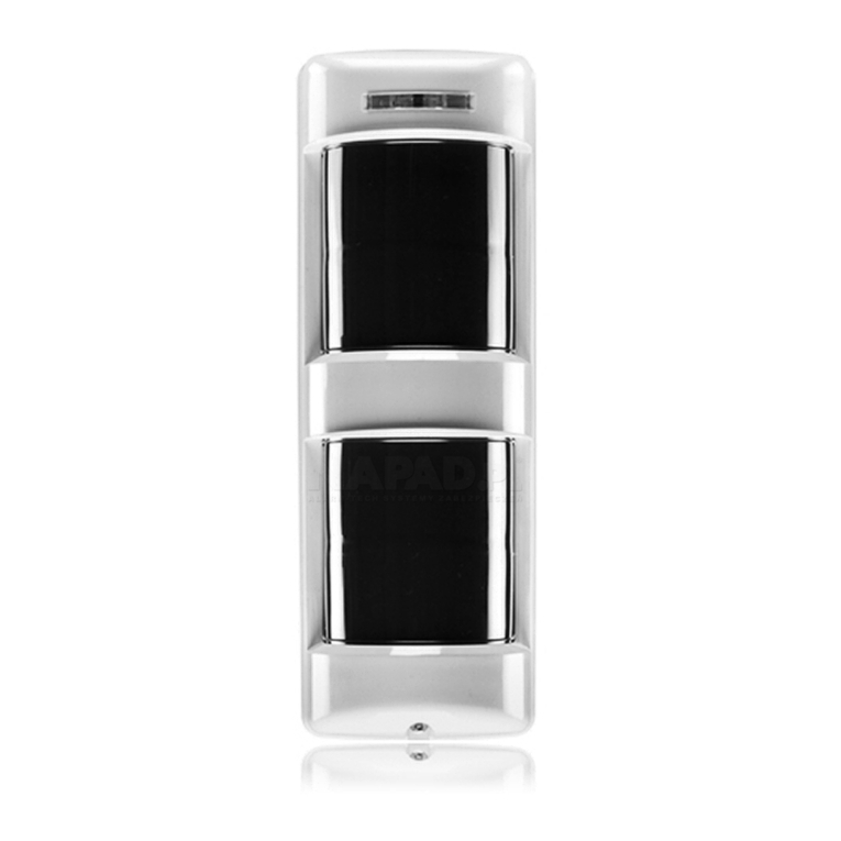
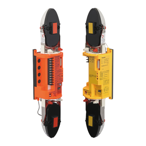
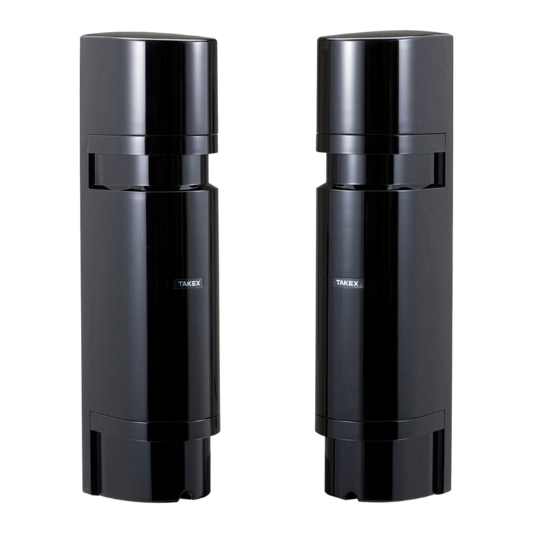
Takex MX-12FAMD User manual

①
352'8&7'(6&5,37,21
P
Avoid spraying water
with a hose
Install perpendicularly Microwave may detect
objects behind a wall.
Avoid adjacent
installation
Follow these mounting condition
Avoid detection of cars/motorcycles on
the roadside.
The detection zone
extends to 12m ahead; there
is a
possibility of detecting vehicles with
temperature differences.
Keep installation height
0.8 to 1.2m(2.6' to 4.0')
WRP
WR
,QFUHDVH 'HFUHDVH
5DQJHLQZKLFK
SHRSOHDUHGHWHFWHG
5DQJHLQZKLFK
FDUVDUHGHWHFWHG
'HWHFWLRQ
Do not disassemble or alter this product.
Do not connect devices which exceed the capacitance of this sensor.
Strictly observe the specified voltage (9 to 28V DC).
Immediately stop power supply in the event of abnormal condition.
Do not use the sensor in a location with high humidity.
Mount the sensor securely in the optimal position.
Immediately stop power supply in the event of water entry.
Warning
Caution
An action you must do and information you should keep in mind.
A prohibited action you must not do.
Avoid electrical noise Avoid exhaust vent Remove all obstructions Avoid strong light and fluorescent lamp at
a short distance
Ensure that people cross
the detection area
Remove obstructions,
including glass
1RWGHWHFWHGE\3,5
Thank you for your purchase of this TAKEX dual zone outdoor PIR.
This sensor will provide a long and dependable service when properly installed. Please read this Instruction Manual carefully for correct
and effective use.
Please Note :
This indicates the possibility of severe injury, and even death, if ignored or a user handles the unit incorrectly.
Instruction Manual
DUAL ZONE OUTDOOR PIR
MX-12FAMD
MX-12FAMD is a dual-technology outdoor motion detection sensor which uses dual-zone PIR and microwave technologies to detect the
movement of a human.
Suitable for indoor/outdoor use, this sensor provides detection coverage
of 12 m×180 degrees, with independent
outputs for alarm and external devices per left/right side (90 degree), adjustable individually.
This sensor is designed to detect intrusion and to initiate an alarm; it is not a burglary-preventing device. TAKEX is
not responsible for any damage, injury, or loss caused by accident, theft, Acts of God (including lightning), abuse,
misuse, abnormal usage, faulty installation or improper maintenance.
This indicates the possibility of minor injury and/or damage to properties, or a possible notification delay in your
system due to false operations and/or non-detection, if ignored or a user handles the unit incorrectly.
For reliable
detection at 12m
distance, install at
a height of 1.1m or
more (max.1.2m)
35(&$87,216
※
'HWHFWHGE\0LFURZDYH

②
Accessory
6HOIWDSSLQJVFUHZ
SFV
$UHDPDVNLQJVKHHW
SFV
)ROGHGDQGVWRUHG
LQVLGHWKHFRYHU
&RYHU
/HQV
2SHUDWLRQ
/('
&RYHU/RFNLQJVFUHZ
0RGHVHWWLQJ%
'LVWDQFH
DGMXVWPHQW
OHYHU
:LULQJKROH
0RXQWLQJKROH
0RXQWLQJKROH
Loosen the cover locking screw and remove the cover.
(6) Fix the sensor using the supplied screws.
[Embedded wiring ]
(1) Align the back of sensor with the wiring from the wall.
(2)
Feed the wiring through the wiring hole and connect it to the terminals.
(3) Use sealant and caulk the gap around the wiring.
[External wiring ]
(1) Break off the desired knockout before wiring.
(2)
Feed the wiring through the wiring hole and connect it to the terminals.
(3) Use cable conduit and joint boxes to cover the wiring.
(4) Use sealant to caulk the gap around the wiring.
(5)
Select Active or Inactive back tamper by reversing the rubber switch cover.
$FWLYH)DFWRU\VHW
,QDFWLYH
%DFN7DPSHU
Make sure that sealant is used to caulk the
wiring hole and gaps.
%DFNWDPSHU
7HUPLQDOV
.QRFNRXW
.QRFNRXW
3-1 Before mounting
3-2 Wall mount
0RGHVHWWLQJ$
WRP
WR
',3VZLWFK
',3VZLWFK
3$576'(6&5,37,21
,167$//$7,21

③
* Use the pole attachment BP-32 sold separately.
(for pole dia 38mm to 45mm (1.50" to 1.77"))
(1) Break off the pole mounting knockouts.
(2) Fit the pole mounting brackets to the sensor.
(3) Select Active or Inactive Back Tamper by reversing the rubber switch cover.
(4) Use sealant to caulk the screw hole and the gap around wiring entry.
(5)
Fit the pole fixing bracket around the pole and fix the sensor with screws.
(6)
Make sure that the sensor is not inclined when viewed in front or laterally.
Make sure that sealant is used to caulk the
wiring hole and screw hole.
Power voltage
Size of wire used
12V DC 24V DC
AWG22 0.3mm2(φ0.65mm)
AWG20 0.5mm2(φ0.8mm)
AWG18 0.8mm2(φ1.0mm)
AWG16 1.3mm2(φ1.3mm)
Wire size: AWG24 〜AWG16 (0.2mm2〜1.3mm2)
Maximum wiring distance
=Value of Power voltage / Number of sets
Max. signal line distance: 1,000m (3,000ft.)
(with AWG 22 (dia. 0.65mm) telephone wire)
NOTE: 1)
2)
①② ③④⑤⑥⑦⑧⑨⑩
POWER
ALARM OUTPUT (1)
ALARM OUTPUT (2)
TROUBLE OUTPUT
TAMPER OUTPUT
: 9 to 28V DC (non-polarity) Current consumption 30mA max.
: N.C./N.O. selectable, 30V (AC/DC) 0.2A max. (Resistive load)
(For EXTERNAL OUTPUT : N.O. only)
: N.C. 30V (AC/DC) 0.2A max. (Resistive load)
: N.C. 30V (AC/DC) 0.1A max. (Resistive load)
①②
32:(5
③④
$/$50
$/$505,*+7 $/$50/()7
⑤⑥
$/$50
(;7(51$/
287387
⑦⑧
7528%/(
⑨⑩
7$03(5
Mode setting “A-2” OFF
Mode setting “A-2” ON
$/$50
5,*+7/()7
3ROHPRXQWLQJ
EUDFNHW
%3
.QRFNRXW
.QRFNRXW
.QRFNRXW
.QRFNRXW
:LULQJKROH
6FUHZKROH
6FUHZKROH
4-1 Terminal configuration
4-2 Wiring distance
3-3 Pole mount
350m (1100’)
550m (1800’)
850m (2800’)
(4600’)
1400m
1700m (5600’)
2800m (9200’)
4400m (14500’)
7100m (23000’)
:,5,1*

④
7239,(:
6,'(9,(:
P
P
P
P
P
P
15°
·
·
·
·
·
·
P PP
P
P
P
P
/()76(1625
&29(5$*(
5,*+76(1625
&29(5$*(
IMPORTANT NOTES
[Wide angle detection]
Detection range/sensitivity may change depending on the following factors:
・Small difference of temperature between object and surroundings.
・Movement direction of the object.
・Mounting height.
・Mounting orientation.
・Slope in detection area.
P P
P
P
P P
P
P
P P
P
P
5-1 Detection area
0:5DQJH6KRUWPD[P
0:5DQJH/RQJPD[P
0:5DQJH/RQJPD[P
0LFURZDYH
]RQHUDQJH
6KRUW /RQJ
PD[P
PD[P
Downward
zone
Downward
zone
Downward
zone
Detection range
Horizontal zone
Horizontal zone
Detection range
Detection range
Horizontal zone
Detected
Detected
Not detected
+RUL]RQWDO]RQH
+RUL]RQWDO]RQH
'RZQZDUG]RQH
>UDQJHV@
'RZQZDUG]RQH
>UDQJHV@
LEFT
SENSOR
RIGHT
SENSOR
3,5
3,5
3,5
3,5
Alarm signal is issued only when both
horizontal and downward PIR zones and
Microwave zone detect objects.
Small animals which are not likely to reach
the height of horizontal PIR zone will not be
detected.
It does not detect vehicles moving in the area
outside the range of the downward PIR zone.
As microwave is not affected by temperature variation of
the object, the sensor makes stable detection performance.
Downward
zone
Horizontal zone
Detection range
MW zone
Not detected
MW zone
OHIWDQGULJKW
VHWLQGLYLGXDOO\
· ·
·
·
·
·
· · ·
·
· · ·
·
· · ·
·
· · ·
6(77,1*
Not detected
GGG
GGG
GGG

⑤
212))
$/$50
)81&7,21
0,&52:$9(
5$1*(
>5,*+76,'(@
$/$50
287387
$/$50
3URWHFWLRQGHJUHHV :DOOZLQGRZSURWHFWLRQ
٘6HWWKHSXOVHFRXQWWR
〔)DFWRU\VHW〕
3DUWLDOPDVNLQJ
>/()76,'(@
1&
12
>)DFWRU\VHW@
>)DFWRU\VHW@
2))
21
2))
21
$/$50
$/$50 $/$50
5LJKW/HIW
5LJKW /HIW
([WHUQDORXWSXWWR
&DPHUDRUDQFLOODU\GHYLFH
12RQO\
(1) Pull out the area masking sheet from the cover.
(2) Bend or cut off the sheet to adjust it to the masking area.
(3) Clip the mask to the protruding hooks around the optical unit.
- In case of wall detection, set the pulse count to 1.
- Carry out a walk test and check the detection area.
9$&$17
MODE SETTING A
212))
212))
$/$50287387
$/$50)81&7,21
0,&52:$9(5$1*(
0,&52:$9(5$1*(
121&
2)) 21
Cut off / Bend
$
%
&
'
()*+,
-
.
/
0
+WR0
]RQHV
$
%
&
'
()*+,
-
.
/
0
%WR*
]RQHV +WR/
]RQHV
$
%
&
'
()*+,
-
.
/
0
'),
5-2 PIR area masking
5-3 Switch setting
6KRUW /RQJ
6KRUW /RQJ
02'(6(77,1*$
212))
〔)DFWRU\VHW〕
02'(6(77,1*%
2))
RIGHT SIDE
LEFT SIDE
0,&52:$9((19
0,&52:$9((19
RIGHT SIDE
LEFT SIDE
MODE SETTING A MODE SETTING B
21
2))
/21*
>)DFWRU\VHW@
6+257
21
2))
21
2))
21
2))
/21*
>)DFWRU\VHW@
6+257
5LJKW
/HIW
6KRUW
/RQJ
6KRUW
/RQJ
$17,0$6.,1*
02'(6(77,1*%
3,56(16,7,9,7<
3,56(16,7,9,7<
212))
38/6(&2817
RIGHT SIDE
LEFT SIDE
/Y
/Y
/Y
/Y
$17,0$6.,1*
(19,5210(17$/
/(9(/
3,56(16,7,9,7<
>5,*+76,'(@
$17,0$6.,1*
2)) 21
>)DFWRU\VHW@
2)) 21
21
2))
2)) 21
>)DFWRU\VHW@
3,56(16,7,9,7<
>/()76,'(@
38/6(&2817
2)) 21
21
>)DFWRU\VHW@
21
2))
2))
2)) 21
>)DFWRU\VHW@
2)) 21
21
2))
21
2))
>)DFWRU\VHW@
2))
21
5LJKW
/HIW
$17,0$6.,1*
(19,5210(17$/
/(9(/
*
/Y /Y
/Y /Y
*If the anti-masking function does not work properly depending on
the environment, change the setting appropriately.
Lv.0 ⇒Lv.3
(normal)
(high)
0,&52:$9(
(19,5210(17
>5,*+76,'(@
>/()76,'(@
*
2))>)DFWRU\VHW@
21
2))>)DFWRU\VHW@
21
*In the environment where the microwave sensor is easily
affected, set the DIP switch setting ON.

⑥
No
No
Alarm detection
Low supply voltage**
LED operationStatus Recovery
Blinking (approx. 1min)
Blinking rapidly
Blinking slowly
Lights (approx. 2sec)
Lights continuously
Mode setting “A-2” ON: Left and Right / OFF : Left or Right
Warm-up
Masking detection
Self diagnosis error*
Walk test
Operation
Walk test
Operation
0.15 0.15
0.85
0.5
0.15 0.15 0.15 0.15
0.1 0.10.6
(1) Replace the cover to automatically start the operation check and walk test function (for 5 min) after approx. 1 min of LED blinking.
(2) Check that the LED lights on both detection sides (left and right) within the set detection area.
(3) Readjust the detection area if necessary.
(4) Anti-masking performs learning function for 3 min after the cover is replaced. For this to be successful, do not have any object
within 10cm of the lens during this period.
(5) Check also operation of connected devices, when applicable.
(1) No power supply (including broken wiring), or the
power supply voltage is low.
(2) The detection area is blocked by an object (which may
include glass).
(3) Unsuitable detection area settings (including
detection distance).
(4) Approximately 1 minute has not passed since turning
the power ON.
(1) Check the power wiring, and power supply voltage.
ĺ[:,5,1*]
(2) Remove obstacles.
(3) Readjust detection area. ĺ[6(77,1*]
(4) Wait approximately 1 minute.
(1) Unsuitable detection area settings (including
detection distance).
(2)
The detection lens is covered with dust or water droplets.
(3) Unsuitable detection or pulse count settings.
(1) Readjust detection area. ĺ[6(77,1*]
(2) Clean the lens with a damp soft cloth, and wipe off
water droplets.
(3)
Readjust the settings.
ĺ[6(77,1*]
(1) Wiring failure, broken wire, or short-circuit.
(2) Check that connected devices are operating correctly.
(1) Connect wiring correctly.
(2) Investigate with reference to the instruction manuals
of the connected devices.
(1) Unstable power supply voltage.
(2) Something is moving within the detection area, or
there are sudden changes in temperature.
(3) A source of electrical noise (broadcasting station,
amateur radio station, etc.) is nearby.
(4) Direct or reflected light such as sunlight or headlights
sometimes shines onto the sensor itself or into the
detection area.
(5) The sensor is mounted on an angle (the horizontal
zone is tilted).
(6) Cars or motorcycles are sometimes detected at the
edge of the detection area.
(1) Ensure appropriate power supply voltage.
(2) Identify the problem object, and remove it.
(3) Change the mounting location or remove the noise source.
ĺ[35(&$87,216]
(4) Change the mounting location, or location of the reflective
item.
Readjust detection area.
Use the area masking sheet to hide zones for which detection is
not required. ĺ[
6(77,1*]
(5) Change the mounting location.
ĺ[6(77,1*]
(6) Reduce the set distance. Readjust detection area.
ĺ[6(77,1*]
Trouble Check Corrective Action
The sensor does not
detect anything
The sensor sometimes
does not detect anything
The sensor generates
an alarm, although
there are no people
within detection area
The operation LED is on,
but connected devices are
not operating.
Solve possible problems according to the following table. If normal operations cannot be
restored by this means, contact either the dealer from whom you bought the unit or TAKEX.
0.5
0.5
*Detection and notification of the problems caused by broken wiring inside the sensor, malfunction, etc.
**Monitoring and notification in case input power supply voltage to the sensor is reduced.
Return to the normal status by
power supply reset
Return to the normal voltage by
power supply reset
[sec]
[sec]
[sec]
(LED’s corresponding to left/right zones)
Mode setting “A-2” ON: Left and Right / OFF : Left or Right
(LED’s corresponding to left/right zones)
6-1 Operation check
6-2 LED indication
Red
Green
MW detection
Red
Red
Red
Red
Lights (2sec max., Priority : Alarm (Red))
Output
Alarm detection Alarm output(1)(2)
Masking detection Alarm output(1)(2)
Trouble output
Output
StatusStatus
Cover tamper detection
Self diagnosis error
Low supply voltage
Back tamper detection
Trouble output
Tamper output
6-3 Output
&+(&.,1*
7528%/(6+227,1*
After resolving the cause, either open/
close the cover, or allow the unit 15
seconds reset time without motion and
then activate twice
⑦
Model MX-12FAMD
Detection system Passive infrared and Microwave
Detection area
Horizontal detection
Angle : 180°, Detection distance : 12m(40')
Horizontal zone : 14 zones Downward zone : 14 zones
PIR Area adjustment
Detection distance : 2 to 12m(10' to 40') [10 ranges]
(by adjusting vertical angle of downward curtain)
Supply voltage 9 to 28V DC (non-polarity)
Current consumption
Alarm output (1)
Alarm output (2)
40mA max.
ALARM RIGHT+LEFT
ALARM RIGHT
ALARM LEFT
EXTERNAL OUTPUT
Tamper output
Dry contact relay output N.C.
Contact capacity : 30V (AC/DC) 0.1A max.(Resistive load)
Trouble output
Dry contact relay output N.C.
Contact capacity : 30V (AC/DC) 0.2A max.(Resistive load)
Operation LED
Red LED
・Warm-up (Blinking)
・Alarm detection (Lights approx.2sec only for Walk test)
・Low supply voltage (Blinking slowly)
・Masking detection (Blinking rapidly)
・Self diagonosis error (Lights continuously)
Dry contact relay output N.C./N.O. selectable
・Contact capacity : 30V (AC/DC) 0.2A max. (Resistive load)
・Contact operation : Detection time (+2sec.)
Dry contact relay output N.C./N.O. selectable
・Contact capacity : 30V (AC/DC) 0.2A max. (Resistive load)
・Contact operation : Detection time (+2sec.)
Dry contact relay output N.O.
・Contact capacity : 30V (AC/DC) 0.2A max. (Resistive load)
・Contact operation : Detection time (+30sec. latch time)
Pulse count 1 / 3 times (selectable with DIP switch)
PIR sensitivity adjustment
60% / 80% / 100% / 120% (selectable with DIP switch, left and right sensors individually)
Functions Anti-masking, Microwave environment, Back tamper, Trouble alarm, Low voltage monitoring
Anti-masking Environmental level
Connection Terminals
Ambient temperature -25°C to + 60°C (-13°F to + 140°F)
Mounting position Indoor / Outdoor
Ingress protection IP55 (Wall mount)
Weight 400g (14.2oz)
Optional Pole attachment : BP-32
Appearance Body : resin (white) / Lens : resin (white)
left and right adjustment individually possible
(Cover tamper / Back tamper (when enabled))
(Masking detection / Low supply voltage / Self diagonosis error)
※Specifications and design are subject to change without prior notice.
Short / LongMicrowave
range adjustment
Green LED
・Microwave alarm detection (Lights max.2sec only for Walk test)
Microwave transmit
frequency and power 24.150 to 24.250GHz 12.7dBm e.i.r.p
(selectable with DIP switch, left and right sensors individually)
MAINTENANCE
1. Clean the device with a soft, damp cloth and wipe off water drops. Use water with weak neutral detergent to clean stubborn
dirt. (except lens)
Do not use substances such as thinner or benzene.
2. Perform operation check on a regular basis.
63(&,),&$7,216

⑧
PP PP
PP
PP
PP
PP
.QRFNRXWPP×PP
.QRFNRXWPP×PP
µ
2SHUDWLRQ/('
&RYHUORFNLQJVFUHZ
02817+2/(
µ
%DFN7DPSHU
ѮPP
PP
PP
PP
:LULQJVSDFH
µ
µ
µ
µ×µ
µ×µ
µ
Ѯµ
µ
µ µ
TAKEX hereby declares that the radio equipment type MX-12FAMD is in compliance with RE Directive 2014/53/EU.
The full text of the EU declaration of conformity is available at the following internet address ; www.takex.com
This equipment complies with EU radiation exposure limits set forth for an uncontrolled environment.
(;7(51$/',0(16,216
63(&,$/127(6
No.06-152
C1013
,Q-DSDQ
Takex America Inc.Takenaka Engineering Co., Ltd.
KWWSVZZZWDNH[HQJFRMS
Takex America Inc.
KWWSVZZZWDNH[FRP
Takex Europe Ltd.
KWWSVZZZWDNH[FRP
,QWKH86 ,QWKH8.
,Q$XVWUDOLD
$YLDU\&RXUW:DGH5RDG
%DVLQJVWRNH+DPSVKLUH5*3(8.
7HO
)D[
+RZOH\V5RDG1RWWLQJ+LOO
9,&
7HO
)D[
KWWSVZZZWDNH[FRP
*RMR'RUL6RWRNDQ1LVKLLUX+LJDVKLQR
<DPDVKLQDNX.\RWR-DSDQ
7HO
2DNODQG5G6XLWH)
6DQ-RVH&$86$
7HO
)D[
Limited Warranty :
TAKEX products are warranted to be free from defects in material and workmanship for 12 months from original date of shipment. Our warranty does not cover damage or
failure caused by Acts of God (including inductive surge by lightning), abuse, misuse, abnormal usage, faulty installation, improper maintenance or any repairs other than
those provided by TAKEX. All implied warranties with respect to TAKEX, including implied warranties for merchantability and implied warranties for fitness, are limited in
duration to 12 months from original date of shipment. During the Warranty Period, TAKEX will repair or replace, at its sole option, free of charge, any defective parts
returned prepaid. Please provide the model number of the products, original date of shipment and nature of difficulty being experienced. There will be charges rendered for
product repairs made after our Warranty period has expired.
Table of contents
Other Takex Security Sensor manuals

Takex
Takex PA-6614E User manual

Takex
Takex SSP-S200 Series User manual

Takex
Takex FP-5500E User manual

Takex
Takex PR-5B User manual

Takex
Takex PIR-T45WP User manual

Takex
Takex Quad PB-IN-50HF User manual

Takex
Takex PB-30SU User manual

Takex
Takex PB-100AT-KH User manual

Takex
Takex PA-6812E User manual

Takex
Takex TXF-125-KH User manual
Popular Security Sensor manuals by other brands

Aritech
Aritech GS620N installation manual

New Focus
New Focus 1480 user guide

Menvier
Menvier 800 Series quick start guide

Online Electronics
Online Electronics ID5000P operating manual

Nivel System
Nivel System CLS-3 user manual

Homematic IP
Homematic IP HmIP-SMI55-2 Mounting instruction and operating manual