* HOOD PIN HOOD STATUS : THE HOOD PIN SWITCH MUST BE INSTALLED
IF THE VEHICLE CAN BE REMOTE STARTED WITH THE HOOD OPEN.
CONTACT
DE CAPOT
MANDATORY INSTALL | INSTALLATION OBLIGATOIRE Notice: the installation of safety
elements are mandatory. The hood pin
is an essential security element and
must be installed.
Notice: l'installation des éléments de
sécurité est obligatoire. Le contact de
capot est un élément de sécurité
essentiel et doit absolument être
installé.
THIS MODULE MUST BE INSTALLED BY A
QUALIFIED TECHNICIAN. A WRONG
CONNECTION CAN CAUSE PERMANENT
DAMAGE TO THE VEHICLE.
CE MODULE DOIT ÊTRE INSTALLÉ PAR
UN TECHNICIEN QUALIFIÉ, TOUTE
ERREUR DANS LES BRANCHEMENTS
PEUT OCCASIONNER DES DOMMAGES
PERMANENTS AU VÉHICULE.
STATUT DE CAPOT : LE CONTACT DE CAPOT, DOIT ÊTRE INSTALLÉ SI LE
VÉHICULE PEUT DÉMARRER À DISTANCE, LORSQUE LE CAPOT EST OUVERT.
ADDENDUM - SUGGESTED WIRING CONFIGURATION
ADDENDA - SCHÉMA DE BRANCHEMENT SUGGÉRÉ
ALL REV.: 20180927
Copyright © 2014,
1
910
2 3 4
11 12
5
13
7 8
15 16
67
14
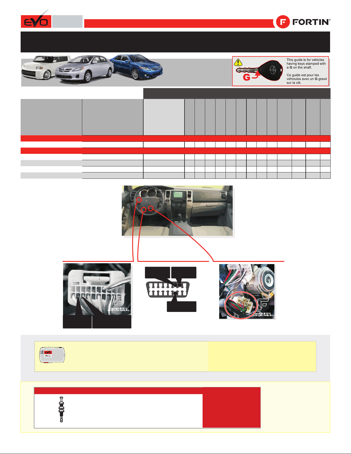
ADDENDUM - SUGGESTED WIRING CONFIGURATION
SCHÉMA DE BRANCHEMENT SUGGÉRÉ
G-KEY (80-BIT)
SCION / TOYOTA
2011-2013
G Key (80-BIT)
OBD-II connector
Connecteur OBD-II
This manual may change without notice.
www.ifar.ca for latest version.
Ce Guide peut faire l'objet de changement sans préavis.
www.ifar.ca pour la récente version.
NOTE : functional if equipped with a factory hood switch.
fonctionnel si équipé d'un commutateur de capot d'origine.
Hood Status
Page 1 / 5 Rev.20120408 GUIDE # BETA
Ignition connector
Connecteur Ignition
AutoLight
Rav4
Camry
Corolla
Matrix
XB
2010-2011
G Key (80-BIT)
2010-2013
G Key (80-BIT)
2010-2014
G Key (80-BIT)
2011-2012
G Key (80-BIT)
CAN HIGH
Pin 6
CAN LOW
Pin 14
IMMO DATA
Pin 7
Parking Light switch harness
Harnais feux de stationnement
(-)Parking Lights(-)AutoLight
Copyright © 2014,
Date: xx-xx
HARDWARE VERSION : 3
FIRMWARE VERSION : 4.0+
Service No : 000 102 04 2536
INTERFACE MODULE
Made in Canada
PATENTS PENDING US: 2007-228827-A1
www.fortinbypass.com
EVO
HARDWARE VERSION
VERSION DU MATÉRIEL
5
Minimum
FIRMWARE VERSION
VERSION DU LOGICIEL
[ ]
Minimum
79.
Toyota/Lexus 12
1
910
2 3 4
11 12
5
13
7 8
15 16
67
14
ADDENDUM - SUGGESTED WIRING CONFIGURATION
SCHÉMA DE BRANCHEMENT SUGGÉRÉ
G-KEY (80-BIT)
SCION / TOYOTA
2011-2013
G Key (80-BIT)
G
80-bit
OBD-II connector
Connecteur OBD-II
HARDWARE VERSION
VERSION DU MATÉRIEL
Date: xx-xx
HARDWARE VERSION : 3
FIRMWARE VERSION : 4.0+
Service No : 000 102 04 2536
INTERFACE MODULE
Made in Canada
PATENTS PENDING US: 2007-228827-A1
www.fortinbypass.com
EVO
3
Minimum
NOTE : functional if equipped with a factory hood switch.
fonctionnel si équipé d'un commutateur de capot d'origine.
Hood Status
Page 1 / 5 Rev.20120408 GUIDE # BETA
Ignition connector
Connecteur Ignition
Copyright © 2012,
Fortin Auto Radio Inc
AutoLight
Rav4
Camry
Corolla
Matrix
XB
2010-2011
G Key (80-BIT)
2012-2013
G Key (80-BIT)
2010-2013
G Key (80-BIT)
2011-2012
G Key (80-BIT)
CAN HIGH
Pin 6
CAN LOW
Pin 14
IMMO DATA
Pin 7
FIRMWARE VERSION
VERSION DU LOGICIEL
[ ]
Minimum
0379.
Toyota/Lexus
Copyright © 2010,
Fortin Auto Radio Inc
Parking Light switch harness
Harnais feux de stationnement
Copyright © 2012,
Fortin Auto Radio Inc
(-)Parking Lights(-)AutoLight
Auto-Light Control
This manual may change without notice.
www.fortinbypass.com for latest version.
Ce Guide peut faire l'objet de changement sans préavis.
www.fortinbypass.com pour la récente version.
Vehicle functions supported in this diagram (functional if equipped) | Fonctions du véhicule
supportées dans ce diagramme (fonctionnelles si équipé)
VEHICLE
YEARS
Immobilizer
bypass
Contournement
d’immobilisateur
Guide # 29551
HARDWARE VERSION
VERSION MATÉRIELLE FIRMWARE VERSION
VERSION LOGICIELLE
To add the rmware version and the options, use the
FLASH LINK UPDATER or FLASH LINK MOBILE tool,
sold separately.
Pour ajouter la version logicielle et les options,
utilisez l’outil FLASH LINK UPDATER
ou FLASH LINK MOBILE, vendu séparément.
MINIMUM 6 79.[47]
TOYOTA/LEXUS/SUBARU MINIMUM
Page 1 / 5
REGULAR INSTALLATION
INSTALLATION RÉGULIÈRE


