manuals.online logo
Brands
  1. Home
  2. •
  3. Brands
  4. •
  5. Fortin
  6. •
  7. Remote Starter
  8. •
  9. Fortin FTXDUO EVO-START2ANT User manual

Fortin FTXDUO EVO-START2ANT User manual

INSTALL GUIDE
GUIDE D’INSTALLATION
INSTALL GUIDE
REV.: 20180125
WWW.EVO-START.CA
WWW.FORTIN.CA
WARNING MISE EN GARDE
Neither the manufacturer or distributor of this module is
responsible for damages of any kind either indirectly or
directly caused by this module, except for the replacement of
this module in case of manufacturing defects. This module
must be installed by a qualied technician. This instruction
guide may change without notice.
Visit WWW.FORTIN.CA or WWW.EVO-START.CA to obtain the
latest version.
Ni le manufacturier, ni le distributeur ne se considèrent
responsables des dommages causés ou ayant pu être causés,
indirectement ou directement, par ce module, excepté le
remplacement de ce module en cas de défaut de fabrication.
Ce module doit être installé par un technicien qualié. Ce
guide d’instruction peut faire l’objet de changement sans
préavis.
Consultez le WWW.FORTIN.CA ou
WWW.EVO-START.CA pour voir la plus récente version.
1X RFA2A (low power connector) RFA2A (connecteur basse puissance)
1X EVO-ONE or
E400 or
EVO-ALL
EVO-ONE ou
E400 ou
EVO-ALL
RFA 2A POWER ADAPTOR ADAPTEUR D'ALIMENTATION RFA 2A
1X FLASH LINK UPDATER FLASH LINK UPDATER
1X
Microsoft Windows Computer & Internet
connection
Ordinateur Microsoft Windows & connection
Internet
PARTS REQUIRED (NOT INCLUDED) PIÈCES REQUISES (NON INCLUSES)
TABLE OF CONTENT TABLE DES MATIÈRES
Page 1 / 17
INSTALL WITH :
INSTALLATION AVEC :
EVO-ONE* ............................................................. PAGES 2 - 6
E400* ...................................................................... PAGES 7 - 10
EVO-ALL STANDALONE* .................................. PAGES 11 - 14
DIAGNOSTICS ......................................................................... PAGES 15
DIAGNOSTIQUES
RESET ...................................................................................... PAGES 17
RÉINITIALISATION
*Sold separately
*Vendu séparément
GUIDE # 69731
EVO-START2ANT
Page 2 / 17 EVO-START2ANT
REMOTE STARTER FIRMWARE
VERSION
VERSION LOGICIELLE DU
DÉMARREUR À DISTANCE
1. [21]
MINIMUM
EVO-ONE
A
WWW.FORTIN.CA VISIT WWW.FORTIN.CA ALLER AU WWW.FORTIN.CA
B
EVO-ONE CHOOSE THE MODEL AND YEAR
OF YOUR VEHICLE AND SELECT
THE GUIDE FOR EVO-ONE.
CHOISIR LE MODÈLE ET L’ANNÉE
DU VÉHICULE ET SÉLECTIONNER
LE GUIDE D’INSTALLATION POUR LE
PRODUIT EVO-ONE.
C
OPTIONAL : A T-HARNESS FOR
THE VEHICULE CAN BE AVAILABLE
(SOLD SEPARATELY).
OPTIONNEL : UN T-HARNAIS DU
VÉHICULE PEUT ÊTRE DISPONIBLE
(VENDU SÉPARÉMENT).
D
DOWNLOAD THE INSTALLATION
GUIDE FOR THE VEHICULE.
TÉLÉCHARGER LE GUIDE
D'INSTALLATION DU VÉHICULE.
E
CONNECT AND USE ONE OF
THE AVAILABLE WIRING FOR
EVO-START2ANT (CONNECTION 1,
2 AND 3)
BRANCHER ET UTILISER L'UN
DES BRANCHEMENTS DISPONIBLES
POUR LE EVO-START2ANT
(CONNECTION 1, 2 ET 3).
EVO-ONE INSTALLATION & PROGRAMMING INSTALLATION ET PROGRAMMATION EVO-ONE
Page 3 / 17 EVO-START2ANT
EVO-START2
ANT
ANTENNA
ANTENNE
EVO-START2
ANT
INSTALLATION: Place the antenna 3 inch
(minimum) from any obstructions.
ORIENTATION: Vertical, antenna facing
downwards (as shown)
INSTALLATION: Placer l’antenne à 3
pouces (minimum) de tout obstacle.
ORIENTATION:
Verticale, l’antenne
tournée vers le bas
(tel qu’indiqqué)
*Sold separately
*Vendu séparément
BLACK 6-PIN
ANTENNA
CONNECTOR
CONNECTEUR
6-PIN ANTENNE
EVO-START
ANTENNA
ANTENNE
EVO-START
FMH
2-W
INSTALLATION:
Place the antenna
3 inch (minimum)
from any
obstructions.
ORIENTATION:
Vertical, antenna
facing downwards
(as shown)
INSTALLATION:
Placer l’antenne à
3 pouces
(minimum) de tout
obstacle.
ORIENTATION:
Verticale, l’antenne
tournée vers le bas
(tel qu’indiqqué)
6 INCH
MINIMUM
6 POUCES
MINIMUM
FMH ANTENNA*
ANTENNE FMH*
FMH ANTENNA*
USE THE CABLE
INCLUDED WITH THE
ANTENNA.
ANTENNE FMH*
UTILISER LE CÂBLE
INCLUS AVEC
L’ANTENNE.
OPTIONAL
OPTIONEL BLUE 4-PIN FEMALE ANTENNA
CONNECTOR
CONNECTEUR 4-PIN FEMELLE
ANTENNE
YELLOW | JAUNE (+)IGNITION
(+)IGNITION
NOT CONNECTED
NON BRANCHÉ
BLACK 4-PIN DATA-LINK
T-HARNESS* CONNECTOR
CONNECTEUR 4-PIN
DATA-LINK DU T-HARNAIS*
BLACK 4-PIN DATA-LINK
T-HARNESS*
CONNECTOR
CONNECTEUR 4-PIN
DATA-LINK DU
T-HARNAIS*
T-HARNESS* AVAILABLE
*Optional - Sold separately
depending on the vehicle.
---------------------
HARNAIS EN T* DISPONIBLE:
*Optionnel - vendu séparement
selon le véhicule.
IF THIS CONNECTOR IS
NOT USED:
Protect the pin
connector with electrical
tape to prevent any
shortcircuit.
SI CE CONNECTEUR
N’EST PAS UTILISÉ:
Isolez les contacts avec
du ruban électrique
pour éviter tout
court-circuit.
BLUE 4-PIN MALE
ANTENNA CONNECTOR
CONNECTEUR 4-PIN
MÂLE ANTENNE
HIGH POWER CONNECTIONS
(more than 3AMP required for EVO-ONE operation)
BRANCHEMENTS HAUTE PUISSANCE
(plus de 3AMP requis au fonctionnement du EVO-ONE)
CONNECTION 1 EVO-ONE INSTALLATION CONNECTION 1 INSTALLATION EVO-ONE
Page 4 / 17 EVO-START2ANT
CONNECTION 2 - EVO-ONE INSTALLATION CONNECTION 2 - INSTALLATION EVO-ONE
LOW POWER CONNECTION
(3amp MAX.)
BRANCHEMENTS BASSE PUISSANCE
(3amp MAX.)
EVO-START2
ANT
ANTENNA
ANTENNE
EVO-START2
ANT
INSTALLATION: Place the antenna 3 inch
(minimum) from any obstructions.
ORIENTATION: Vertical, antenna facing
downwards (as shown)
INSTALLATION: Placer l’antenne à 3
pouces (minimum) de tout obstacle.
ORIENTATION:
Verticale, l’antenne
tournée vers le bas
(tel qu’indiqqué)
*Sold separately
*Vendu séparément
BLACK 6-PIN
ANTENNA
CONNECTOR
CONNECTEUR
6-PIN ANTENNE
EVO-START
ANTENNA
ANTENNE
EVO-START
FMH
2-W
INSTALLATION:
Place the antenna
3 inch (minimum)
from any
obstructions.
ORIENTATION:
Vertical, antenna
facing downwards
(as shown)
INSTALLATION:
Placer l’antenne à
3 pouces
(minimum) de tout
obstacle.
ORIENTATION:
Verticale, l’antenne
tournée vers le bas
(tel qu’indiqqué)
6 INCH
MINIMUM
6 POUCES
MINIMUM
FMH ANTENNA*
ANTENNE FMH*
FMH ANTENNA*
USE THE CABLE
INCLUDED WITH THE
ANTENNA.
ANTENNE FMH*
UTILISER LE CÂBLE
INCLUS AVEC
L’ANTENNE.
OPTIONAL
OPTIONEL BLUE 4-PIN FEMALE ANTENNA
CONNECTOR
CONNECTEUR 4-PIN FEMELLE
ANTENNE
YELLOW | JAUNE (+)IGNITION
(+)IGNITION
IF THIS CONNECTOR IS
NOT USED:
Protect the pin
connector with electrical
tape to prevent any
shortcircuit.
SI CE CONNECTEUR
N’EST PAS UTILISÉ:
Isolez les contacts avec
du ruban électrique
pour éviter tout
court-circuit.
Red 12V Battery (+)
Black Ground | Masse (-)
FUSIBLE
12V
Battery (+)
Ground
Masse
RFA2A
BLUE FEMALE
CONNECTOR
CONNECTEUR
FEMELLE BLEU
BLACK FEMALE
CONNECTOR
CONNECTEUR
FEMELLE NOIR
NOT CONNECTED
---------------------
NON BRANCHÉ
NOT CONNECTED
---------------------
NON BRANCHÉ
BLACK 4-PIN CONNECTOR
CONNECTEUR 4-PIN NOIR
Sold separately
Vendu séparément
BLUE 4-PIN MALE
ANTENNA CONNECTOR
CONNECTEUR 4-PIN
MÂLE ANTENNE
Page 5 / 17 EVO-START2ANT
CONNECTION 3 - EVO-ONE INSTALLATION CONNECTION 3 - INSTALLATION EVO-ONE
WITH THARNESS*
WITHOUT HIGH POWER
AVEC HARNAIS EN T*
SANS HAUTE PUISSANCE
EVO-START2
ANT
ANTENNA
ANTENNE
EVO-START2
ANT
INSTALLATION: Place the antenna 3 inch
(minimum) from any obstructions.
ORIENTATION: Vertical, antenna facing
downwards (as shown)
INSTALLATION: Placer l’antenne à 3
pouces (minimum) de tout obstacle.
ORIENTATION:
Verticale, l’antenne
tournée vers le bas
(tel qu’indiqqué)
*Sold separately
*Vendu séparément
BLACK 6-PIN
ANTENNA
CONNECTOR
CONNECTEUR
6-PIN ANTENNE
EVO-START
ANTENNA
ANTENNE
EVO-START
FMH
2-W
INSTALLATION:
Place the antenna
3 inch (minimum)
from any
obstructions.
ORIENTATION:
Vertical, antenna
facing downwards
(as shown)
INSTALLATION:
Placer l’antenne à
3 pouces
(minimum) de tout
obstacle.
ORIENTATION:
Verticale, l’antenne
tournée vers le bas
(tel qu’indiqqué)
6 INCH
MINIMUM
6 POUCES
MINIMUM
FMH ANTENNA*
ANTENNE FMH*
FMH ANTENNA*
USE THE CABLE
INCLUDED WITH THE
ANTENNA.
ANTENNE FMH*
UTILISER LE CÂBLE
INCLUS AVEC
L’ANTENNE.
OPTIONAL
OPTIONEL BLUE 4-PIN FEMALE ANTENNA
CONNECTOR
CONNECTEUR 4-PIN FEMELLE
ANTENNE
YELLOW | JAUNE (+)IGNITION
(+)IGNITION
NOT CONNECTED
NON BRANCHÉ
BLACK 4-PIN DATA-LINK
T-HARNESS* CONNECTOR
CONNECTEUR 4-PIN
DATA-LINK DU T-HARNAIS*
BLACK 4-PIN DATA-LINK
T-HARNESS*
CONNECTOR
CONNECTEUR 4-PIN
DATA-LINK DU
T-HARNAIS*
T-HARNESS* AVAILABLE
*Optional - Sold separately
depending on the vehicle.
---------------------
HARNAIS EN T* DISPONIBLE:
*Optionnel - vendu séparement
selon le véhicule.
IF THIS CONNECTOR IS
NOT USED:
Protect the pin
connector with electrical
tape to prevent any
shortcircuit.
SI CE CONNECTEUR
N’EST PAS UTILISÉ:
Isolez les contacts avec
du ruban électrique
pour éviter tout
court-circuit.
BLUE 4-PIN MALE
ANTENNA CONNECTOR
CONNECTEUR 4-PIN
MÂLE ANTENNE
Page 6 / 17 EVO-START2ANT
AON Turn the Ignition ON, you have 5
sec. to complete the step B:
Mettre l’ignition à ON, vous avez
5 sec. pour compléter l’étape B.
WITH VALET BUTTON
AVEC BOUTON VALET
WITHOUT VALET BUTTON
SANS BOUTON VALET
BPress and hold the valet switch until
the parking lights turn ON, the horn/
siren will chirp. OFF
Turn the Ignition OFF.
Appuyez et tenez enfoncé le bouton
valet jusqu’à ce que les feux de posi-
tionnement s’allument et que le klaxon/
sirène retentisse, puis relâchez.
Mettre l’ignition à OFF.
Cx5 Press and release the valet switch ve
times. The parking lights will ash and
the horn/siren will chirp each time to
conrm. ON
Turn the Ignition ON.
Appuyez et relâchez le bouton valet
5 fois. Les feux de positionnement
clignoteront et le klaxon/sirène re-
tentira chaque fois que le bouton est
appuyé.
Mettre l’ignition à ON.
D
x1
Press and release the brake pedal
once.
x4
Press and release the
brake pedal 4 times.
Appuyez et relâchez une fois la pédale
de frein.
Appuyer et relâcher 4
fois sur la pédale de
frein.
WITH A FTX-DUO TRANSMITTER /
AVEC UNE TÉLÉCOMMANDE FTX-DUO
WITHOUT A FTX-DUO TRANSMITTER /
SANS TÉLÉCOMMANDE FTX-DUO
E
...
The EVO-START2ANT will ash blue rapidly.
PRESS
HOLD
Press and hold the
programming button
until the LED turn ON
Green.
L'antenne du EVO-START2ANT clignotera
bleu rapidement.
Appuyer et maintenir le
bouton jusqu’à ce que le
DEL s’allume Verte.
FOn each Transmitter: press and release
the button then press and release the
button.
Sur chacune des télécommandes:
Appuyez et relâchez le bouton ensuite
appuyez et relâchez le bouton .
GThe LED will stop ashing for a second
conrming programming.
La DEL arrête de clignoter 1 seconde
pour conrmer l’apprentissage.
OFF Turn the Ignition OFF to exit
programming mode.
Mettre l’ignition à OFF pour sortir du
mode de programmation.
EVO-ONE - ANTENNA PROGRAMMING EVO-ONE - PROGRAMMATION DE L'ANTENNE
Page 7 / 17 EVO-START2ANT
E400
DATA-LINK
REMOTE STARTER FIRMWARE
VERSION
VERSION LOGICIELLE DU
DÉMARREUR À DISTANCE
1. 21
MINIMUM
E400 INSTALLATION & PROGRAMMING INSTALLATION ET PROGRAMMATION E400
E400
E400
INSTALL WITH E400 ONLY:
INSTALLATION AVEC E400 SEULEMENT:
E400 MAKE THE CONNECTION
AND PROGRAM THE E400 TO
THE VEHICLE.
FAIRE LES BRANCHEMENT
ET PROGRAMMER LE E400 AU
VÉHICULE.
USE THE INSTALLATION GUIDE
SUPPLIED WITH THE E400.
UTILISER LE GUIDE INCLUS
AVEC LE E400.
INSTALL WITH E400 & EVO-ALL:
INSTALLATION AVEC E400 ET EVO-ALL:
HARDWARE
VERSION
VERSION
MATÉRIELLE
MINIMUM 6
AWWW.FORTIN.CA VISIT WWW.FORTIN.CA ALLER AU WWW.FORTIN.CA
B
EVO-ALL CHOOSE THE MODEL AND YEAR
OF YOUR VEHICLE AND SELECT
THE GUIDE FOR EVO-ALL.
CHOISIR LE MODÈLE ET L’ANNÉE
DU VÉHICULE ET SÉLECTIONNER
LE GUIDE D’INSTALLATION POUR
LE PRODUIT EVO-ALL.
C
DOWNLOAD THE EVO-ALL
INSTALLATION GUIDE FOR THE
VEHICULE.
TÉLÉCHARGER LE GUIDE EVO-
ALL DU VÉHICULE.
DE400 MAKE THE DATA-LINK
CONNECTION AND
PROGRAM THE EVO-ALL AND
THE E400 TO THE VEHICLE.
FAIRE LES BRANCHEMENT
EN DATA-LINK ET
PROGRAMMER LE EVO-ALL ET
LE E400 AU VÉHICULE.
HARDWARE
VERSION
VERSION
MATÉRIELLE
MINIMUM 2
Page 8 / 17 EVO-START2ANT
HIGH POWER CONNECTIONS
(more than 3AMP required for E400 operation)
BRANCHEMENTS HAUTE PUISSANCE
(plus de 3AMP requis au fonctionnement du E400)
CONNECTION 1 - E400 INSTALLATION CONNECTION 1 - INSTALLATION E400
EVO-START2
ANT
ANTENNA
ANTENNE
EVO-START2
ANT
INSTALLATION: Place the antenna 3 inch
(minimum) from any obstructions.
ORIENTATION: Vertical, antenna facing
downwards (as shown)
INSTALLATION: Placer l’antenne à 3
pouces (minimum) de tout obstacle.
ORIENTATION:
Verticale, l’antenne
tournée vers le bas
(tel qu’indiqqué)
*Sold separately
*Vendu séparément
BLACK 6-PIN
ANTENNA
CONNECTOR
CONNECTEUR
6-PIN ANTENNE
EVO-START
ANTENNA
ANTENNE
EVO-START
FMH
2-W
INSTALLATION:
Place the antenna
3 inch (minimum)
from any
obstructions.
ORIENTATION:
Vertical, antenna
facing downwards
(as shown)
INSTALLATION:
Placer l’antenne à
3 pouces
(minimum) de tout
obstacle.
ORIENTATION:
Verticale, l’antenne
tournée vers le bas
(tel qu’indiqqué)
6 INCH
MINIMUM
6 POUCES
MINIMUM
FMH ANTENNA*
ANTENNE FMH*
FMH ANTENNA*
USE THE CABLE
INCLUDED WITH THE
ANTENNA.
ANTENNE FMH*
UTILISER LE CÂBLE
INCLUS AVEC
L’ANTENNE.
OPTIONAL
OPTIONEL BLUE 4-PIN FEMALE ANTENNA
CONNECTOR
CONNECTEUR 4-PIN FEMELLE
ANTENNE
YELLOW | JAUNE (+)IGNITION
(+)IGNITION
E400
WHITE 8-PIN
HIGH POWER
CONNECTOR
CONNECTEUR
HAUTE
PUISSANCE
8-PIN
DATA-LINK
Sold separately
Vendu séparément
BLUE 4-PIN MALE
ANTENNA CONNECTOR
CONNECTEUR 4-PIN
MÂLE ANTENNE
Page 9 / 17 EVO-START2ANT
CONNECTION 2 - E400 INSTALLATION CONNECTION 2 - INSTALLATION E400
WITH THARNESS*
WITHOUT HIGH POWER
AVEC HARNAIS EN T*
SANS HAUTE PUISSANCE
EVO-START2
ANT
ANTENNA
ANTENNE
EVO-START2
ANT
INSTALLATION: Place the antenna 3 inch
(minimum) from any obstructions.
ORIENTATION: Vertical, antenna facing
downwards (as shown)
INSTALLATION: Placer l’antenne à 3
pouces (minimum) de tout obstacle.
ORIENTATION:
Verticale, l’antenne
tournée vers le bas
(tel qu’indiqqué)
*Sold separately
*Vendu séparément
BLACK 6-PIN
ANTENNA
CONNECTOR
CONNECTEUR
6-PIN ANTENNE
EVO-START
ANTENNA
ANTENNE
EVO-START
FMH
2-W
INSTALLATION:
Place the antenna
3 inch (minimum)
from any
obstructions.
ORIENTATION:
Vertical, antenna
facing downwards
(as shown)
INSTALLATION:
Placer l’antenne à
3 pouces
(minimum) de tout
obstacle.
ORIENTATION:
Verticale, l’antenne
tournée vers le bas
(tel qu’indiqqué)
6 INCH
MINIMUM
6 POUCES
MINIMUM
FMH ANTENNA*
ANTENNE FMH*
FMH ANTENNA*
USE THE CABLE
INCLUDED WITH THE
ANTENNA.
ANTENNE FMH*
UTILISER LE CÂBLE
INCLUS AVEC
L’ANTENNE.
OPTIONAL
OPTIONEL BLUE 4-PIN FEMALE ANTENNA
CONNECTOR
CONNECTEUR 4-PIN FEMELLE
ANTENNE
YELLOW | JAUNE (+)IGNITION
(+)IGNITION
E400
IF THIS CONNECTOR IS NOT USED:
Protect the pin connector with electrical
tape to prevent any shortcircuit.
SI CE CONNECTEUR N’EST PAS UTILISÉ:
Isolez les contacts avec du ruban
électrique pour éviter tout court-circuit.
BLACK 4-PIN DATA-LINK
T-HARNESS* CONNECTOR
CONNECTEUR 4-PIN
DATA-LINK DU T-HARNAIS*
BLACK 4-PIN DATA-LINK
T-HARNESS*
CONNECTOR
CONNECTEUR 4-PIN
DATA-LINK DU
T-HARNAIS*
Sold separately
Vendu séparément
BLUE 4-PIN MALE
ANTENNA CONNECTOR
CONNECTEUR 4-PIN
MÂLE ANTENNE
T-HARNESS* AVAILABLE
*Optional - Sold separately
depending on the vehicle.
---------------------
HARNAIS EN T* DISPONIBLE:
*Optionnel - vendu séparement
selon le véhicule.
Page 10 / 17 EVO-START2ANT
E400 - ANTENNA PROGRAMMING E400 - PROGRAMMATION DE L'ANTENNE
AON Turn the Ignition ON, you have 5
sec. to complete the step B:
Mettre l’ignition à ON, vous avez
5 sec. pour compléter l’étape B.
WITH VALET BUTTON
AVEC BOUTON VALET
WITHOUT VALET BUTTON
SANS BOUTON VALET
B
E400
Press and hold the valet switch until
the parking lights turn ON, the horn/
siren will chirp. OFF
Turn the Ignition OFF.
Appuyez et tenez enfoncé le bouton
valet jusqu’à ce que les feux de posi-
tionnement s’allument et que le klaxon/
sirène retentisse, puis relâchez.
Mettre l’ignition à OFF.
Cx5
E400
Press and release the valet switch ve
times. The parking lights will ash and
the horn/siren will chirp each time to
conrm. ON
Turn the Ignition ON.
Appuyez et relâchez le bouton valet
5 fois. Les feux de positionnement
clignoteront et le klaxon/sirène re-
tentira chaque fois que le bouton est
appuyé.
Mettre l’ignition à ON.
D
x1
Press and release the brake pedal
once.
x4
Press and release the
brake pedal 4 times.
Appuyez et relâchez une fois la pédale
de frein.
Appuyer et relâcher 4
fois sur la pédale de
frein.
WITH A FTX-DUO TRANSMITTER /
AVEC UNE TÉLÉCOMMANDE FTX-DUO
WITHOUT A FTX-DUO TRANSMITTER /
SANS TÉLÉCOMMANDE FTX-DUO
E
...
The EVO-START2ANT will ash blue rapidly.
PRESS
HOLD
Press and hold the
programming button
until the LED turn ON
Green.
L'antenne du EVO-START2ANT clignotera
bleu rapidement.
Appuyer et maintenir le
bouton jusqu’à ce que le
DEL s’allume Verte.
FOn each Transmitter: press and release
the button then press and release the
button.
Sur chacune des télécommandes:
Appuyez et relâchez le bouton ensuite
appuyez et relâchez le bouton .
GThe LED will stop ashing for a second
conrming programming.
La DEL arrête de clignoter 1 seconde
pour conrmer l’apprentissage.
OFF Turn the Ignition OFF to exit
programming mode.
Mettre l’ignition à OFF pour sortir du
mode de programmation.
Page 11 / 17 EVO-START2ANT
ALL
NOT INCLUDED.
NON INCLUS.
HARDWARE
VERSION
VERSION
MATÉRIELLE
MINIMUM 6
EVO-ALL INSTALLATION & PROGRAMMING INSTALLATION ET PROGRAMMATION EVO-ALL
OUI
ON
; ALARM
; REMOTE STARTER
; ALARME
; DÉMARREUR À DISTANCE
OUI
ON
OUI
ON
OUI
ON
; ALARM
; ALARME
; REMOTE STARTER
; DÉMARREUR À DISTANCE
CHOOCE YOUR INSTALLATION TYPE CHOISIR SON MODE D'INSTALLATION
OUI
ON
D1 - Fonction démarreur
autonome
D1 - OEM Stand Alone
Remote Starter
OUI
ON
H- Kit RF supportés
H- Supported RF Kits &&&
&
G- Système d’Alarme Evo
G- Evo Alarm System
G- Système d’Alarme Evo
G- Evo Alarm System
D1 - Fonction démarreur
autonome
D1 - OEM Stand Alone
Remote Starter
H- Kit RF supportés
H- Supported RF Kits
OUI
ON
H2 - Fortin2
OUI
ON
H2 - Fortin2
OUI
ON
H- Kit RF supportés
H- Supported RF Kits
OUI
ON
H2 - Fortin2
EVO-ALL CONFIGURATION | CONFIGURATION DU EVO-ALL
Connect the EVO-ALL* module to the Flash Link Updater 2*.
(*Sold separately)
Brancher le module EVO-ALL* au Flash Link Updater 2*.
(*Vendu séparément)
Modify the following options and click ‘SAVE OPTIONS’
Modier les options suivantes et cliquez sur ‘ENREGISTRER LES OPTIONS’
SOFTWARE | PROGRAMME
DOWNLOAD GUIDE # 16221 AT WWW.FORTIN.CA
--------------------------------------------------------
TÉLÉCHARGEZ LE GUIDE # 16221 AU WWW.FORTIN.CA
ALL
AWWW.FORTIN.CA VISIT WWW.FORTIN.CA ALLER AU WWW.FORTIN.CA
B
EVO-ALL & STAND ALONE
CHOOSE THE MODEL AND YEAR
OF YOUR VEHICLE AND SELECT
THE STAND ALONE GUIDE FOR
EVO-ALL.
CHOISIR LE MODÈLE ET L’ANNÉE
DU VÉHICULE ET SÉLECTIONNER
LE GUIDE D’INSTALLATION STAND
ALONE POUR LE PRODUIT EVO-ALL.
C
DOWNLOAD THE INSTALLATION
GUIDE FOR THE VEHICULE.
TÉLÉCHARGER LE GUIDE DU
VÉHICULE.
D
ALL
CONNECT
AND PROGRAM
THE EVO-ALL TO THE VEHICLE.
BRANCHER
ET PROGRAMMER
LE EVO-ALL AU VÉHICULE.
EVO-ALL
-12°C | 05:14 min
Actual temperature inside
the vehicle option NOT
AVAILABLE.
Option de la température à
l’intérieur du véhicule NON
DISPONIBLE.
Page 12 / 17 EVO-START2ANT
CONNECTION 1
EVO-ALL STANDALONE INSTALLATION CONNECTION 1
INSTALLATION AUTONOME EVO-ALL
WITH THARNESS* AVEC HARNAIS EN T*
EVO-START2
ANT
ANTENNA
ANTENNE
EVO-START2
ANT
INSTALLATION: Place the antenna 3 inch
(minimum) from any obstructions.
ORIENTATION: Vertical, antenna facing
downwards (as shown)
INSTALLATION: Placer l’antenne à 3
pouces (minimum) de tout obstacle.
ORIENTATION:
Verticale, l’antenne
tournée vers le bas
(tel qu’indiqqué)
*Sold separately
*Vendu séparément
BLACK 6-PIN
ANTENNA
CONNECTOR
CONNECTEUR
6-PIN ANTENNE
EVO-START
ANTENNA
ANTENNE
EVO-START
FMH
2-W
INSTALLATION:
Place the antenna
3 inch (minimum)
from any
obstructions.
ORIENTATION:
Vertical, antenna
facing downwards
(as shown)
INSTALLATION:
Placer l’antenne à
3 pouces
(minimum) de tout
obstacle.
ORIENTATION:
Verticale, l’antenne
tournée vers le bas
(tel qu’indiqqué)
6 INCH
MINIMUM
6 POUCES
MINIMUM
FMH ANTENNA*
ANTENNE FMH*
FMH ANTENNA*
USE THE CABLE
INCLUDED WITH THE
ANTENNA.
ANTENNE FMH*
UTILISER LE CÂBLE
INCLUS AVEC
L’ANTENNE.
OPTIONAL
OPTIONEL
BLACK 4-PIN DATA-LINK
T-HARNESS* CONNECTOR
CONNECTEUR 4-PIN
DATA-LINK DU T-HARNAIS*
BLACK 4-PIN DATA-LINK
T-HARNESS*
CONNECTOR
CONNECTEUR 4-PIN
DATA-LINK DU
T-HARNAIS*
NOT CONNECTED
NON BRANCHÉ
NOT CONNECTED
NON BRANCHÉ
BLUE 4-PIN MALE ANTENNA
CONNECTOR
CONNECTEUR 4-PIN MÂLE
ANTENNE
T-HARNESS* AVAILABLE
*Optional - Sold separately
depending on the vehicle.
---------------------
HARNAIS EN T* DISPONIBLE:
*Optionnel - vendu séparement
selon le véhicule.
BLUE 4-PIN FEMALE ANTENNA CONNECTOR
CONNECTEUR 4-PIN FEMELLE ANTENNE
Red
Black
BLUE FEMALE
CONNECTOR
CONNECTEUR
FEMELLE BLEU
BLACK FEMALE
CONNECTOR
CONNECTEUR
FEMELLE NOIR
BLACK 4-PIN CONNECTOR
CONNECTEUR 4-PIN NOIR
Sold separately
Vendu séparément
ISOLATE
NOT CONNECTED
---------------------
ISOLER
NON BRANCHÉ
ISOLATE
NOT CONNECTED
---------------------
ISOLER
NON BRANCHÉ
YELLOW | JAUNE (+)IGNITION
(+)IGNITION
RFA2A
WITH FMH ANTENNA*
AVEC ANTENNE FMH*
Page 13 / 17 EVO-START2ANT
CONNECTION 2
EVO-ALL STANDALONE INSTALLATION CONNECTION 2
INSTALLATION AUTONOME EVO-ALL
WITHOUT THARNESS* SANS HARNAIS EN T*
EVO-START2
ANT
ANTENNA
ANTENNE
EVO-START2
ANT
INSTALLATION: Place the antenna 3 inch
(minimum) from any obstructions.
ORIENTATION: Vertical, antenna facing
downwards (as shown)
INSTALLATION: Placer l’antenne à 3
pouces (minimum) de tout obstacle.
ORIENTATION:
Verticale, l’antenne
tournée vers le bas
(tel qu’indiqqué)
*Sold separately
*Vendu séparément
BLACK 6-PIN
ANTENNA
CONNECTOR
CONNECTEUR
6-PIN ANTENNE
EVO-START
ANTENNA
ANTENNE
EVO-START
FMH
2-W
INSTALLATION:
Place the antenna
3 inch (minimum)
from any
obstructions.
ORIENTATION:
Vertical, antenna
facing downwards
(as shown)
INSTALLATION:
Placer l’antenne à
3 pouces
(minimum) de tout
obstacle.
ORIENTATION:
Verticale, l’antenne
tournée vers le bas
(tel qu’indiqqué)
6 INCH
MINIMUM
6 POUCES
MINIMUM
FMH ANTENNA*
ANTENNE FMH*
FMH ANTENNA*
USE THE CABLE
INCLUDED WITH THE
ANTENNA.
ANTENNE FMH*
UTILISER LE CÂBLE
INCLUS AVEC
L’ANTENNE.
OPTIONAL
OPTIONEL BLUE 4-PIN FEMALE ANTENNA
CONNECTOR
CONNECTEUR 4-PIN FEMELLE
ANTENNE
YELLOW | JAUNE (+)IGNITION
(+)IGNITION
Red 12V Battery (+)
Black Ground | Masse (-)
FUSIBLE
12V
Battery (+)
Ground
Masse
RFA2A BLACK FEMALE
CONNECTOR
CONNECTEUR
FEMELLE NOIR
NOT CONNECTED
---------------------
NON BRANCHÉ
BLACK 4-PIN
CONNECTOR
CONNECTEUR
4-PIN NOIR
Sold separately
Vendu séparément
BLUE FEMALE
CONNECTOR
CONNECTEUR
FEMELLE BLEU
BLUE 4-PIN MALE
ANTENNA CONNECTOR
CONNECTEUR 4-PIN
MÂLE ANTENNE
Page 14 / 17 EVO-START2ANT
ALL
CONNECT
AND PROGRAM
THE EVO-ALL TO THE VEHICLE.
BRANCHER
ET PROGRAMMER
LE EVO-ALL AU VÉHICULE.
A
Unplug the EVO-ALL 4Pin
(Data-Link) connector.
Débrancher le connecteur
4pins (Data-Link) du EVO-ALL.
BPress and hold the EVO-
ALL programming button:
Reinsert the 4-Pin (Data-
Link) connector.
Appuyer et maintenir enfoncé
le bouton de programmation DU
EVO-ALL:
Insérez le connecteur 4 pins
(Data-Link)
CRelease the programming
button when LEDs are
Blue & Red.
Relâcher le bouton de program-
mation quand les DELs sont
Bleue et Rouge sont allumées.
If the LED are not solid Blue and
Red disconnect the 4-Pin con-
nector (Data-Link) and go back
to step E.
Si les LED ne sont pas ALLUMÉES
Bleue et Rouge, débrancher le con-
necteur 4 pins (Data-Link) et allez au
début de l’étape E
D
OFF
OFF Press and hold the pro-
gramming button until the
Blue and Red LED turn
back ON.
Peser et garder appuyé le
bouton de programmation
jusqu’à ce que les DELS Bleue
et Rouge se rallument.
EVO-ALL - PROGRAMMING EVO-ALL - PROGRAMMATION
WITH A FTX-DUO TRANSMITTER /
AVEC UNE TÉLÉCOMMANDE FTX-DUO
WITHOUT A FTX-DUO TRANSMITTER /
SANS TÉLÉCOMMANDE FTX-DUO
E
ON
...
Turn the Ignition ON.
PRESS
HOLD
Press and hold the
programming button
until the LED turn
ON Green.
Mettre l’ignition à ON.
The EVO-START2ANT will ash blue
rapidly.
L'antenne du EVO-START2ANT
clignotera bleu rapidement.
Appuyer et
maintenir le bouton
jusqu’à ce que le
DEL s’allume Verte.
FOn each Transmitter: press and
release the button then press
and release the button.
Sur chacune des
télécommandes: Appuyez et
relâchez le bouton ensuite
appuyez et relâchez le bouton
.
OFF Turn the Ignition OFF to exit
programming mode.
Mettre l’ignition à OFF pour sortir du
mode de programmation.
Page 15 / 17 EVO-START2ANT
DIAGNOSTICS DIAGNOSTIQUES
Led Display Event Action
1x Red, 1x Green, 1x Blue Boot Sequence N/A
Fast Purple Blink Installer Mode for Validation testing Cycle ignition OFF to send an Unlock command
Fast Amber Blink Factory Reset Restart EVO-START2ANT programming
1x Constant Amber Blink Unable to sync with Digital Remote
starter during EVO-START power-up
Disconnect and Re-connect EVO-START main
harness. Verify Protocol selection.
2x Constant Amber Blink Validation pending (make sure that the
EVO-START yellow (+) ignition wire is properly
connected to the vehicle's (+) ignition wire.)
Perform Validation Step:
a. Disconnect the EVO-START2ANT unit
b. Cycle ignition to the ON position
c. Re-Connect the EVO-START2ANT unit (DO NOT
Press the programming button)
d. The LED will blink Purple rapidly for 15 seconds
e. During this period, Cycle ignition to the OFF
position
f. If the vehicle door’s unlocks, your programming is
successful.
7x Amber Blink Pit-Stop Mode Not Available
Shutdown and Restart vehicle's engine and
retry Pit-stop mode and/or wrong DATA-LINK
communication port
1x Green Blink Command sent to Remote starter
succeeded
Remote starter will execute the command sent from
EVO-START2ANT unit
1x Amber Blink Command sent to Remote starter failed Verify EVO-START2ANT protocol selection and/or
wrong DATA-LINK communication port
État de la Del Évenement Action
1x Rouge, 1x Verte, 1x
Bleue Séquence de démarrage N/A
Clignotement Rapide
Mauve
Mode installateur pour faire la
Validation
Mettre l'ignition a la position OFF pour envoyer
une commande de Déverrouillage
Clignotement Rapide
Ambre Réinitialisation d’origine Refaire la programmation du module EVO-
START2ANT
1x Clignotement Ambre
Constant
Incapable de syncroniser avec le
démarreur a distance digital durant
la mise sous tension du EVO-START.
Débrancher et Re-brancher le harnais
principal du module EVO-START2ANT. Véerier
la sélection du protocol
Page 16 / 17 EVO-START2ANT
2x Clignotement Ambre
Constant
En attente de Validation (Assurez-vous
que le l jaune, ignition(+), du EVO-START est
bien branché au l d'ignition(+) du véhicule)
Effectuer l’étape de Validation:
a. Débrancher le module EVO-START2ANT
b. Mettre l’ignition à la position ON
c. Re-Brancher le module EVO-START2ANT (NE
PAS appuyer sur le bouton de
programmation )
d. La DEL Mauve clignotera rapidement
pour 15 secondes
e. Durant cette période, mettre l’ignition
à la position OFF
f. Si les portières déverrouillent, votre
programmation est complété.
7x Clignotement Ambre Mode Pit-Stop Non Disponible
Éteindre et redémarrer le moteur du véhicule
et refaire un le mode Pit-Stop et/ou mauvais
port de communication DATA-LINK
1x Clignotement Vert Commande envoyée au démarreur
Conrmée
Le Démarreur a Distance Exécute la
commande envoyé par le module EVO-
START2ANT
1x Clignotement Ambre
Constant
Commande envoyée au démarreur
a échouée
Vérier la sélection de protocol du
EVO-START2ANTet/ou mauvais port de
communication DATA-LINK
Page 17 / 17 EVO-START2ANT
A
REMOVE Disconnect the EVO-START2ANT
Harness.
Débrancher le Harnais
EVO-START2ANT.
B
PRESS
HOLD INSERT
Press and hold the programming
button:
Connect the 6-PIN EVO-
START2ANT harness (Black
connector) in to the antenna.
Appuyer et maintenir le
bouton: Brancher le harnais
EVO-START2ANT à 6-Broches
(connecteur Noir) dans l’antenne.
C
RELEASE
Press and hold the programming
button until the LED turn ON
Amber.
Appuyer et maintenir le bouton
jusqu’à ce que le DEL s’allume
Ambre.
D
REMOVE Disconnect the EVO-START2ANT
Harness.
Débrancher le Harnais
EVO-START2ANT.
E
...
INSERT Connect the 6-PIN EVO-START
harness (Black connector) in to
the antenna.
The LED Blue will alternate
between 1 ashes and a pause.
Brancher le harnais EVO-START
à 6-Broches (connecteur Noir)
dans l’antenne.
La DEL Bleue alternera entre 1
clignotement et 1 pause.
F
PRESS
RELEASE
Press and release the
programming button.
The Blue LED will alternate
between 2 ashes and a pause.
Appuyer et relâcher le bouton de
programmation.
La DEL Bleue alternera entre 2
clignotements et 1 pause.
G
PRESS
HOLD
Press and hold the programming
button until the LED turn ON
Green.
Appuyer et maintenir le bouton
jusqu’à ce que le DEL s’allume
Verte.
HReturn to STEP 3-A to reprogram
the EVO-START2ANT.
Retournez à l’étape 3-A pour
la programmation du EVO-
START2ANT.
ERASES ALL REMOTES THAT
HAVE BEEN PROGRAMMED
DÉPROGRAMMATION DES TÉLÉ-
COMMANDES ENREGISTRÉES

Other manuals for FTXDUO EVO-START2ANT

1

This manual suits for next models

1

Other Fortin Remote Starter manuals

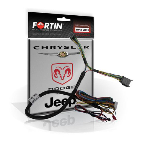
Fortin 12971 User manual

Fortin

Fortin 12971 User manual

Fortin EVO-ALL-CHR4 Assembly instructions

Fortin

Fortin EVO-ALL-CHR4 Assembly instructions

Fortin EVO-START User manual

Fortin

Fortin EVO-START User manual

Fortin EVO ALL User manual

Fortin

Fortin EVO ALL User manual
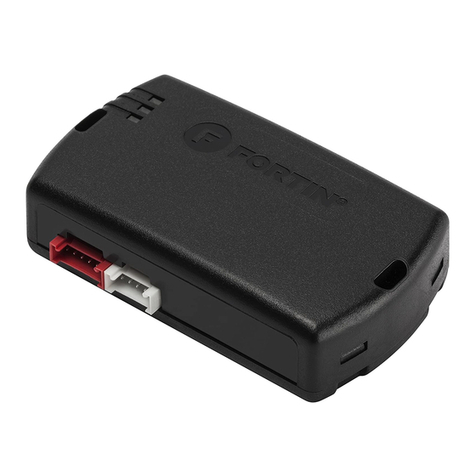
Fortin EVO ALL User manual

Fortin

Fortin EVO ALL User manual

Fortin EVO-ALL User manual

Fortin

Fortin EVO-ALL User manual
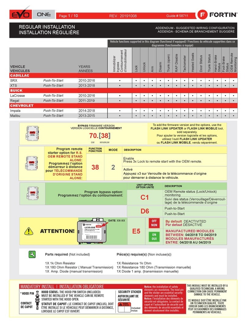
Fortin EVO ONE User manual

Fortin

Fortin EVO ONE User manual

Fortin EVO-ALL User manual

Fortin

Fortin EVO-ALL User manual
Fortin FSA-206 User manual

Fortin

Fortin FSA-206 User manual
Fortin EVO-CAN User manual

Fortin

Fortin EVO-CAN User manual
Fortin GM-SL2 User manual

Fortin

Fortin GM-SL2 User manual
Fortin RM912 User manual

Fortin

Fortin RM912 User manual
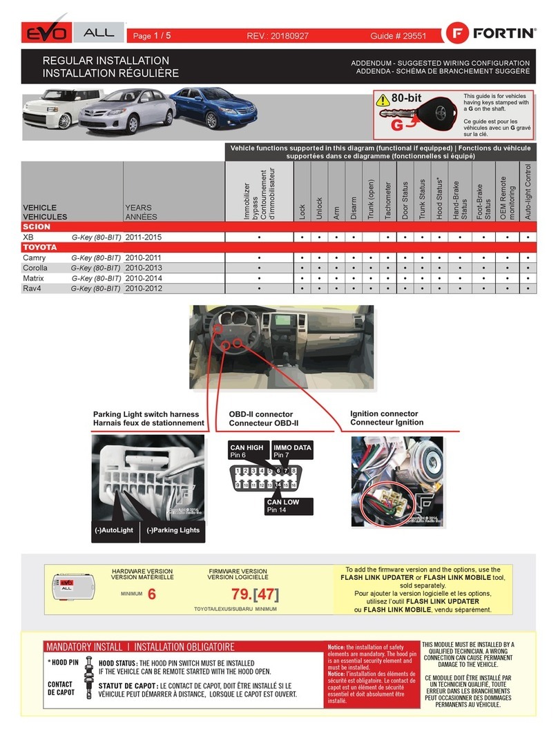
Fortin EVO ALL User manual

Fortin

Fortin EVO ALL User manual

Fortin DL1004 User manual

Fortin

Fortin DL1004 User manual
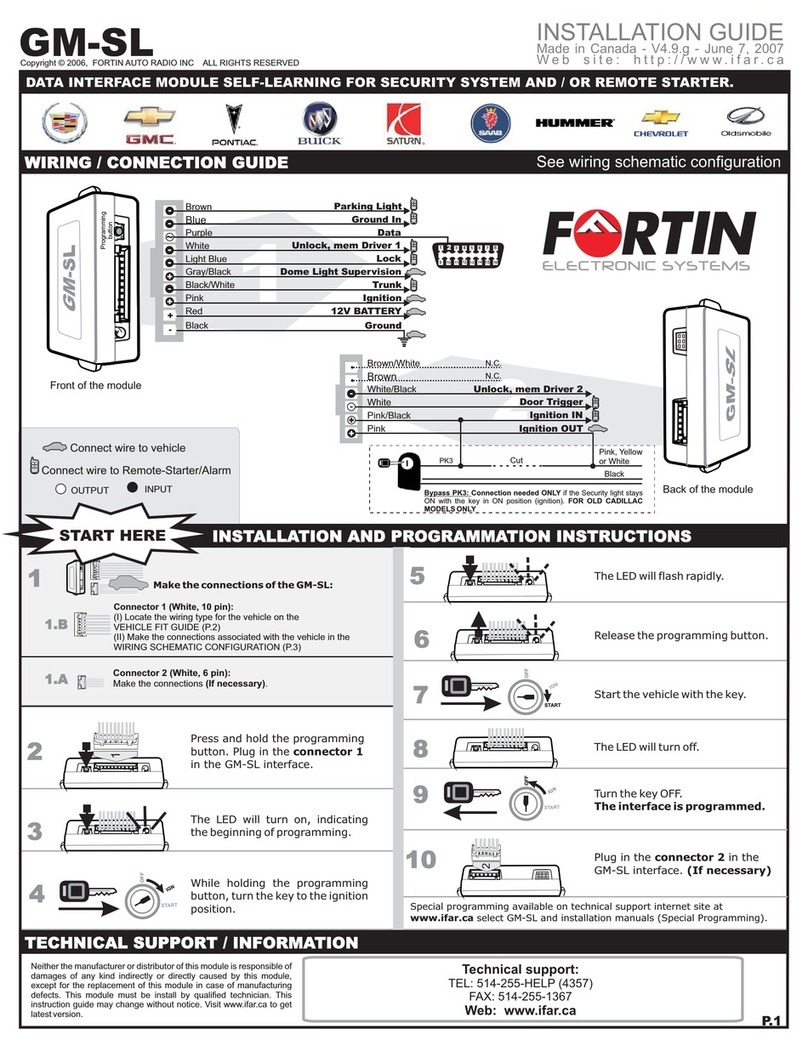
Fortin GM-SL User manual

Fortin

Fortin GM-SL User manual

Fortin EVO ONE User manual

Fortin

Fortin EVO ONE User manual
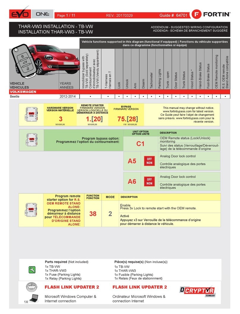
Fortin EVO ONE THAR-VW3 User manual

Fortin

Fortin EVO ONE THAR-VW3 User manual

Fortin EVO-ONE FTX75 User manual

Fortin

Fortin EVO-ONE FTX75 User manual
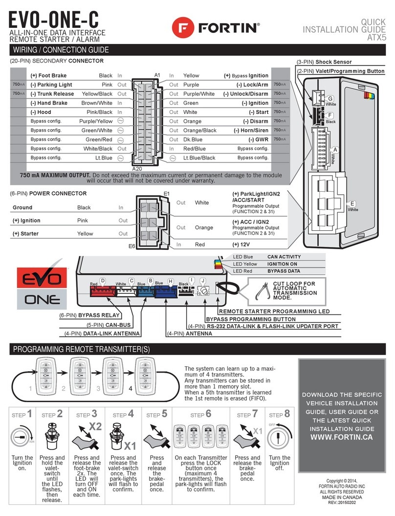
Fortin ATX5 User manual

Fortin

Fortin ATX5 User manual

Fortin EVO ONE User manual

Fortin

Fortin EVO ONE User manual

Fortin EVO-ONE FTX75 User manual

Fortin

Fortin EVO-ONE FTX75 User manual

Fortin EVO-ONE RFK1004 User manual

Fortin

Fortin EVO-ONE RFK1004 User manual

Fortin EVO ONE User manual

Fortin

Fortin EVO ONE User manual

Fortin EVO ONE User manual

Fortin

Fortin EVO ONE User manual

Popular Remote Starter manuals by other brands

Directed Electronics AutoCommand 28624TN Owner's installation guide

Directed Electronics

Directed Electronics AutoCommand 28624TN Owner's installation guide

KBi KrankingKART Operation manual

KBi

KBi KrankingKART Operation manual
Chamberlain 940EV-P2 Getting started

Chamberlain

Chamberlain 940EV-P2 Getting started
Linear WEATHER RESISTANT KEYLESS ENTRY SYSTEM AK-2W Installation and programming instructions

Linear

Linear WEATHER RESISTANT KEYLESS ENTRY SYSTEM AK-2W Installation and programming instructions

Schumacher INSTANT POWER IP-180KE instruction manual

Schumacher

Schumacher INSTANT POWER IP-180KE instruction manual

Audiovox AA-925 installation manual

Audiovox

Audiovox AA-925 installation manual

Viatek Mighty Jump MJ01 instructions

Viatek

Viatek Mighty Jump MJ01 instructions

AKX AKX-CH4-1BAM owner's guide

AKX

AKX AKX-CH4-1BAM owner's guide

Schumacher Electric INSTANT POWER XPF2260 owner's manual

Schumacher Electric

Schumacher Electric INSTANT POWER XPF2260 owner's manual

Otodata C5040/MS-2 Installation procedures

Otodata

Otodata C5040/MS-2 Installation procedures

Avital 4100 owner's guide

Avital

Avital 4100 owner's guide

APA LI600A manual

APA

APA LI600A manual

Directed Electronics 50.7X owner's guide

Directed Electronics

Directed Electronics 50.7X owner's guide

Voxx Electronics PRESTIGE APS901Z owner's guide
Voxx Electronics

Voxx Electronics PRESTIGE APS901Z owner's guide

Wagan iOnBoost v6 7501 user manual

Wagan

Wagan iOnBoost v6 7501 user manual

Durabuilt Durabuilt RD122904 Owner's manual & warranty

Durabuilt

Durabuilt Durabuilt RD122904 Owner's manual & warranty

Motomaster 011-2064-0 instruction manual

Motomaster

Motomaster 011-2064-0 instruction manual

Mopar XBM installation instructions

Mopar

Mopar XBM installation instructions
manuals.online logo
manuals.online logoBrands
  • About & Mission
  • Contact us
  • Privacy Policy
  • Terms and Conditions

Copyright 2025 Manuals.Online. All Rights Reserved.