manuals.online logo
Brands
  1. Home
  2. •
  3. Brands
  4. •
  5. Fortin
  6. •
  7. Remote Starter
  8. •
  9. Fortin GM-SL User manual

Fortin GM-SL User manual

1Make the connections of the GM-SL:
1.A
1.B
Connector 2 (White, 6 pin):
(If necessary)Make the connections .
Connector 1 (White, 10 pin):
(I) Locate the wiring type for the vehicle on the
VEHICLE FIT GUIDE (P.2)
(II) Make the connections associated with the vehicle in the
WIRING SCHEMATIC CONFIGURATION (P.3)
WIRING / CONNECTION GUIDEWIRING / CONNECTION GUIDE
See wiring schematic configuration
DATA INTERFACE MODULE SELF-LEARNING FOR SECURITY SYSTEM AND / OR REMOTE STARTER.
GM-SL
Connect wire to vehicle
Connect wire to Remote-Starter/Alarm
INPUT
OUTPUT
2
3
4
5
6
IGN
START
OFF
7
8
9
IGN
START
OFF
IGN
START
OFF
Press and hold the programming
button. Plug in the
in the GM-SL interface.
connector 1
The LED will turn on, indicating
the beginning of programming.
While holding the programming
button, turn the key to the ignition
position.
The LED will flash rapidly.
Release the programming button.
Start the vehicle with the key.
The LED will turn off.
Turn the key OFF.
The interface is programmed.
P. 1
START HERE
INSTALLATION AND PROGRAMMATION INSTRUCTIONSINSTALLATION AND PROGRAMMATION INSTRUCTIONS
Copyright © 2006, FORTIN AUTO RADIO INC ALL RIGHTS RESERVED
INSTALLATION GUIDE
Made in Canada - V4.9.g - June 7, 2007
Web site: http://www.ifar.ca
1
Programming
button
Brown
Blue
Purple
White
Light Blue
Gray/Black
Black/White
Parking Light
Ground In
Data
Dome Light Supervision
Trunk
Pink Ignition
Red 12V BATTERY
Black Ground
Unlock, mem Driver 1
Lock
1345678
910 11 12 13 14 15 16
2
Special programming available on technical support internet site at
select GM-SL and installation manuals (Special Programming).www.ifar.ca
1
10 Plug in the in the
GM-SL interface.
connector 2
(If necessary)
2
TECHNICAL SUPPORT / INFORMATIONTECHNICAL SUPPORT / INFORMATION
Technical support:
Web: www.ifar.ca
TEL: 514-255-HELP (4357)
FAX: 514-255-1367
Neither the manufacturer or distributor of this module is responsible of
damages of any kind indirectly or directly caused by this module,
except for the replacement of this module in case of manufacturing
defects. This module must be install by qualified technician. This
instruction guide may change without notice. Visit www.ifar.ca to get
latest version.
2
Brown/White
Brown
White/Black
White
Pink/Black
Pink
N.C.
Unlock, mem Driver 2
Ignition OUT
Door Trigger
Ignition IN
N.C.
Cut
Black
Pink, Yellow
or White
PK3
Bypass PK3: Connection needed ONLY
FOR OLD CADILLAC
MODELS ONLY
if the Security light stays
ON with the key in ON position (ignition).
Front of the module
Back of the module
98 99 00 01 02 03 04 05 06 07
98 99 00 01 02 03 04 05 06 07
98 99 00 01 02 03 04 05 06 07
98 99 00 01 02 03 04 05 06 07
98 99 00 01 02 03 04 05 06 07
98 99 00 01 02 03 04 05 06 07
Vehicles
Véhicules
Allure
Century
LaCrosse
LeSabre
Park Avenue
Rainier
Rendez-vous
Terraza
CTS
DeVille
DTS
Escalade
EXT
SLS
SRX
STS
Buick
Cadillac
Chevrolet
GMC
Hummer
Oldsmobile
Saab
9-7X
Aurora
Bravada
Intrigue
Silhouette
Alero
H2
Envoy
Safari
Savana
Sierra
Sierra Classic
Sonoma
Yukon
Astro
Avalanche
Blazer
Cavalier
C/K Pickup
C/K Pickup Classic
Corvette
Express Van
Impala
Monte Carlo
S10 - S15
Silverado
Silverado Classic
Suburban
Tahoe
TrailBlazer
Uplander
Venture
Years
Années
98 99 00 01 02 03 04 05 06 07
Montana 6SV
Montana
Transport
Sunfire
Aztek
Bonneville
Grand Am
Ion
Relay
S Series
Saturn
98 99 00 01 02 03 04 05 06 07
98 99 00 01 02 03 04 05 06 07
Pontiac
VEHICLE FIT GUIDE / GUIDE DES VOITURES
Copyright © 2006, FORTIN AUTO RADIO INC ALL RIGHTS RESERVED
INSTALLATION GUIDE
Made in Canada - V4.9.g - June 7, 2007
Web site: http://www.ifar.ca
GM-SL
AB
AB
AB
AB
AB
AB
Bypass
PK3, Passlock
or VATS
Doorlock
Control
AB
AB
AB
C
C
C
C
C
C
Factory Alarm
Control (OEM)
C
C
C
D
D
D
D
D
D
Trunk
Release
D
D
D
E
E
E
E
E
E
E
E
E
Dome Light
Supervision
F
F
F
F
F
F
Heated Seats
and
Heated Mirrors
(See note)
F
F
F
G
G
G
G
G
G
Rear
Defrost
G
G
G
H
H
H
H
H
H
Parking Light
Control
H
H
H
I
I
I
I
I
I
Retained
Accessory
Power
I
I
I
J
J
J
J
J
J
Memory selection
Driver 1 and 2
(by Unlock)
J
J
J
K
K
K
Wiring
schematic
(seepage 3)
k
1
2
2
2
2
2
1
1
1
2
2
1
1
1
1
2
2
1
2
2
2
2
K
K
1
1
2
2
2
1
1
3
3
3
3
3
3
3
3
3
1
1
2
2
1
1
1
2
2
1
1
1
1
1
1
2
2
2
2
2
2
2
2
1
2
2
K
1
K
K
2
1
1
1
1
3
1
1
1
1
1
2
?
:Functional with 12V Ignition only.
Fonctionne avec ignition 12V
seulement.
: Not TESTED on all models, but
should be functional.
N'a pas été testé surtous les
modèles, mais devrait
fonctionner.
A-
B-
C-
D-
E-
F-
G-
H-
I-
J-
K-
Contournement P 3, Passlock, ou VATS
Verrouillage et déverrouillage des portes
Contrôle d'Alarme d'origine (OEM)
Valise
Supervision lumière plafonnier
Sièges et rétroviseurs chauffants
Dégivreur arrière
Contrôle des feux de stationnement
Radio RAP accessoires
Selection de mémoires conducteur 1 et 2
(par déverrouillage)
Schéma de Branchements (Voir page 3)
K
En Data-Link les entrées analogues
(déverrouillé, ground out) sont
désactivées pour augmenter la
sécurité.
In Data-Link mode the analog Input
(unlock, ground out) are disabled for
security.
P. 2
Technical support:
Web: www.ifar.ca
TEL: 514-255-HELP (4357)
FAX: 514-255-1367
Note : Heated seats will turn ON (low
power) ONLY if the engine temp is below
0°C(32°F)whenremotestarted.
Note : Les sièges chauffants s'allument à
faible intensité SEULEMENT si la
température du moteur est sous 0°C (32°F)
au démarrage.
Titres des colonnes
2
1
1
Interface de branchement Auto-Apprentissage pour Système de Sécurité et /ou Démarreur à distance.
WIRING SCHEMATIC CONFIGURATION / SCHÉMA DE BRANCHEMENT
P. 3
INFORMATION
Neither the manufacturer or distributor of this module is responsible of
damages of any kind indirectly or directly caused by this module,
except for the replacement of this module in case of manufacturing
defects. This module must be install by qualified technician. This
instruction guide may change without notice. isit www.ifar.ca to get
latest version.
V
Ni le manufacturier, ni le distributeur ne se considèrent responsables des
dommages causés ou ayant pu être causés, indirectement ou
directement, par ce module, excepté le remplacement de ce module en
cas de défectuosité de fabrication. Ce module doit être installé par un
technicien qualifié. Ce guide d'instruction peut faire l’objet de
changement sans préavis. Consultez le www.ifar.ca pour voir la plus
récente version.
Copyright © 2006, FORTIN AUTO RADIO INC ALL RIGHTS RESERVED
3
INSTALLATION GUIDE
Made in Canada - V4.9.g - June 7, 2007
Web site: http://www.ifar.ca
GM-SL
1
Brown
Blue
Purple
White
Light Blue
Gray/Black
Black/White
Parking Light
Ground In
Data
N.C
Trunk
Pink Ignition
Red 12V BATTERY
Black Ground
Unlock, mem Driver 1
Lock
1345678
910 11 12 13 14 15 16
22
Brown/White
Brown
White/Black
White
Pink/Black
Pink
N.C.
N.C.
N.C.
N.C.
N.C.
N.C.
1
Brown
Blue
Purple
White
Light Blue
Gray/Black
Black/White
Parking Light
Ground In
Data
Dome Light Supervision
Trunk
Pink Ignition
Red 12V BATTERY
Black Ground
Unlock, mem Driver 1
Lock
1345678
910 11 12 13 14 15 16
2
2
Brown/White
Brown
White/Black
White
Pink/Black
Pink
N.C.
Unlock, mem Driver 2
Ignition OUT
Door Trigger
Ignition IN
N.C.
Pink, Yellow
or White
Cut
Black
PK3
Bypass PK3 seulement:Connexion nécessaire si la lumière Sécurité reste
allumé après avoir tourné la clé à ignition. POURANCIENS MODÈLES
CADILLAC SEULEMENT.
Bypass PK3: Connection needed ONLY
FOR OLD CADILLAC MODELS ONLY
if the Security light stays ON with
the key in ON position (ignition).
1
Brown
Blue
Purple
White
Light Blue
Gray/Black
Black/White
Parking Light
Ground In
Data
Dome Light Supervision
Trunk
Pink Ignition
Red 12V BATTERY
Black Ground
Unlock, mem Driver 1
Lock
1345678
910 11 12 13 14 15 16
22
Brown/White
Brown
White/Black
White
Pink/Black
Pink
N.C.
Unlock, mem Driver 2
Door Trigger
N.C.
N.C.
N.C.
1
1.A
1.B
Connecteur 1 (Blanc, 6 branches):
(Si nécessaire)Faites le connections .
2
3
4
5
6
IGN
START
OFF
7
8
9
IGN
START
OFF
IGN
START
OFF
Programmation spéciale disponible sur le site internet du support technique au
www.ifar.ca sélectionnez GM-SL et manuel d'installation (programmation spéciale).
1
10 Branchez le dans le
module GM-SL.
connecteur 2
(Si nécessaire)
2
Branchement du filage au
démarreur à distance/Alarme
1
Programming
button
Brun
Bleu
Mauve
Blanc
Bleu Pâle
Gris/Noir
Noir/Blanc
Lumière de stationnement
Masse d'activation
Data
Supervision Lumière Plafonnier
Valise
Rose Ignition
Rouge 12V BATTERIE
Noir Masse
Déverrouillage, Conducteur 1
Verrouillage
1345678
910 11 12 13 14 15 16
2
2
Brun/Blanc
Brun
Blanc/Noir
Blanc
Rose/Noir
Rose
N.C.
Déverrouillage, Conducteur 2
Ignition OUT
Contact Portes
Ignition IN
N.C.
Coupez
Noir
Rose, Jaune
ou Blanc
PK3
GUIDE
Fabriqué au V4.9.g - 8 juin 2007
http://www.ifar.ca
D’INSTALLATION
Canada -
Site Internet:
Interface de branchement Auto-Apprentissage pour Système de Sécurité et /ou Démarreur à distance.
CÂBLAGE / GUIDE DE CONNEXIONCÂBLAGE / GUIDE DE CONNEXION
Voir le schéma de branchement
INTERFACE DE BRANCHEMENT AUTO-APPRENTISSAGE POUR SYSTÈME DE SÉCURITÉ ET / OU DÉMARREUR À DISTANCE.
P. 4
INSTRUCTIONS D’INSTALLATION ET DE PROGRAMMATIONINSTRUCTIONS D’INSTALLATION ET DE PROGRAMMATION
COMMENCEZ
ICI
Copyright © 2006, FORTIN AUTO RADIO INC TOUS DROITS RÉSERVÉS
GM-SL
Ni le manufacturier, ni le distributeur ne se considèrent
responsables des dommages causés ou ayant pu être causés,
indirectement ou directement, par ce module, excepté le
remplacement de ce module en cas de défectuosité de
fabrication. Ce module doit être installé par un technicien qualifié.
Ce guide d'instruction peut faire l’objet de changement sans
préavis. Consultez le www.ifar.ca pour voir la plus récente version.
Support Technique:
Web: www.ifar.ca
TEL: 514-255-HELP (4357)
FAX: 514-255-1367
INFORMATIONS / SUPPORT TECHNIQUEINFORMATIONS / SUPPORT TECHNIQUE
Branchement du
filage au véhicule
SORTIE
ENTRÉE Bypass PK3 seulement:Connexion nécessaire si la lumière
Sécurité reste allumé après avoir tourné la clé à ignition. POUR
ANCIENS MODÈLES CADILLAC SEULEMENT.
Effectuez les connexions du GM-SL:
Connecteur 2 (Blanc):
Déterminez le type de branchement selon votre véhicule
(Voir P.2)
Effectuez les branchements selon le type d’installation
(Voir
GUIDE DES VOITURES,
SCHÉMA DE BRANCHEMENT, P.3)
Maintenez le bouton de programmation
enfoncé. Branchez le dans
le module GM-SL.
connecteur 1
Le DEL s’allume pour indiquer le début de
la programmation.
Ne pas relâcher le bouton de
programmation et tourner la clef en
position ignition.
Le DEL clignote rapidement.
Relâchez le bouton de programmation.
Démarrez le véhicule avec la clef.
Le DEL s’éteint.
Tournez la clef à OFF.
Le module est programmé.
Vue de dos du module
Vue de face du module

Other Fortin Remote Starter manuals

Fortin TB-TOYOTA User manual

Fortin

Fortin TB-TOYOTA User manual

Fortin EVO ALL User manual

Fortin

Fortin EVO ALL User manual
Fortin EVO-ONE FTX75 User manual

Fortin

Fortin EVO-ONE FTX75 User manual

Fortin Multi-Link User manual

Fortin

Fortin Multi-Link User manual
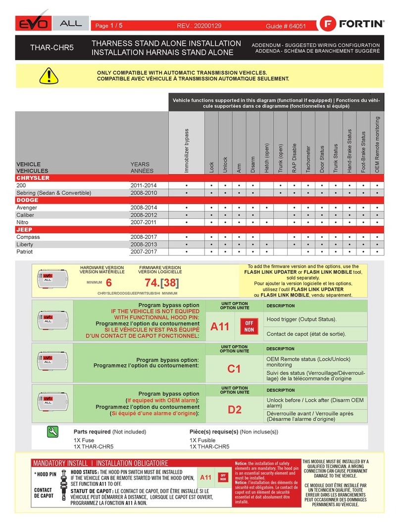
Fortin EVO ALL THAR-CHR5 User manual

Fortin

Fortin EVO ALL THAR-CHR5 User manual

Fortin FS 105 User manual

Fortin

Fortin FS 105 User manual

Fortin DUO CAN 1 User manual

Fortin

Fortin DUO CAN 1 User manual
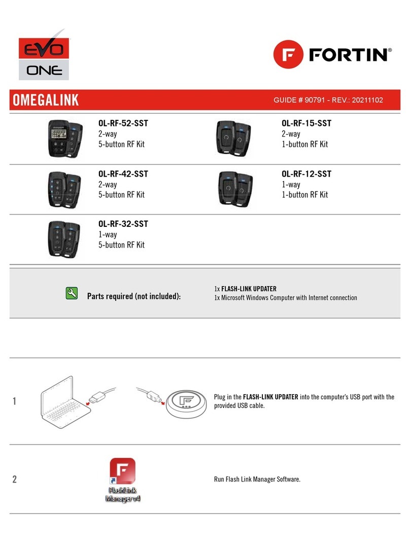
Fortin EVO-ONE User manual

Fortin

Fortin EVO-ONE User manual
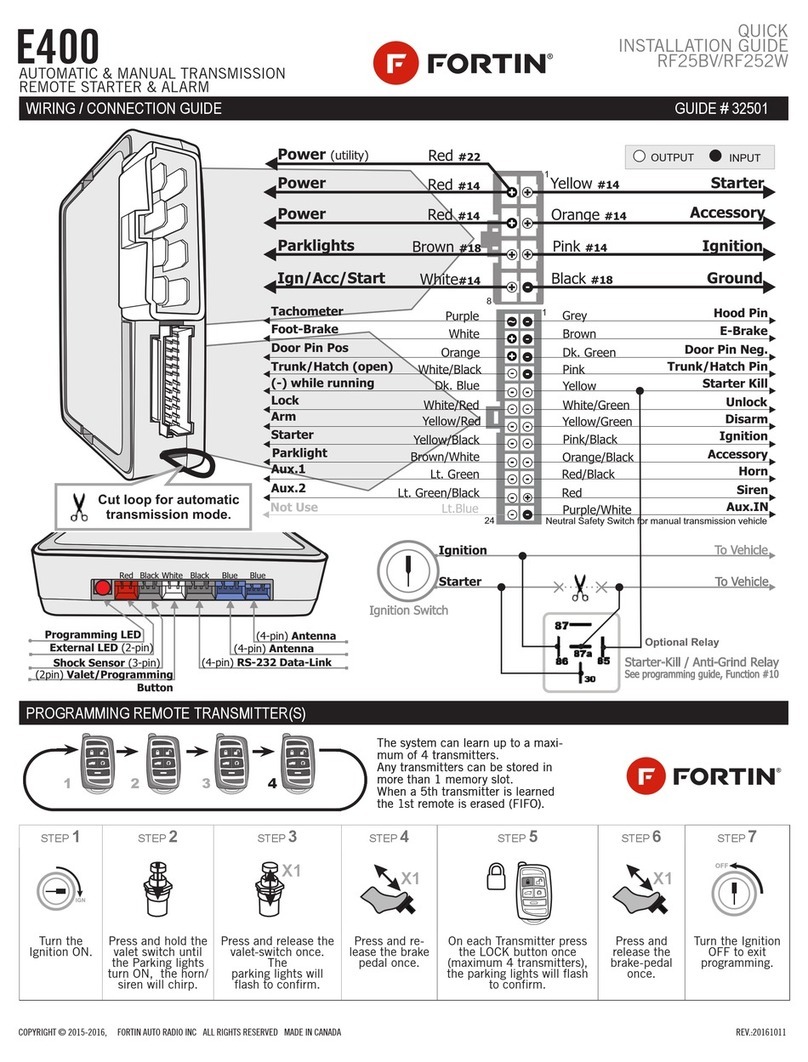
Fortin E400 User manual

Fortin

Fortin E400 User manual
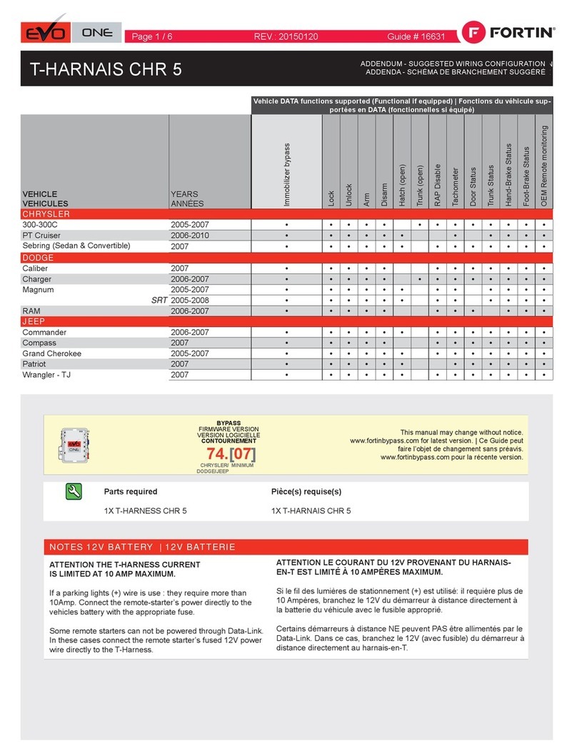
Fortin Evo One T-HARNAIS CHR 5 User manual

Fortin

Fortin Evo One T-HARNAIS CHR 5 User manual

Fortin ANT-FMH-2W User manual

Fortin

Fortin ANT-FMH-2W User manual

Fortin FTX-64-2W User manual

Fortin

Fortin FTX-64-2W User manual

Fortin Evo All 57531 User manual

Fortin

Fortin Evo All 57531 User manual
Fortin FTX84-1W User manual

Fortin

Fortin FTX84-1W User manual
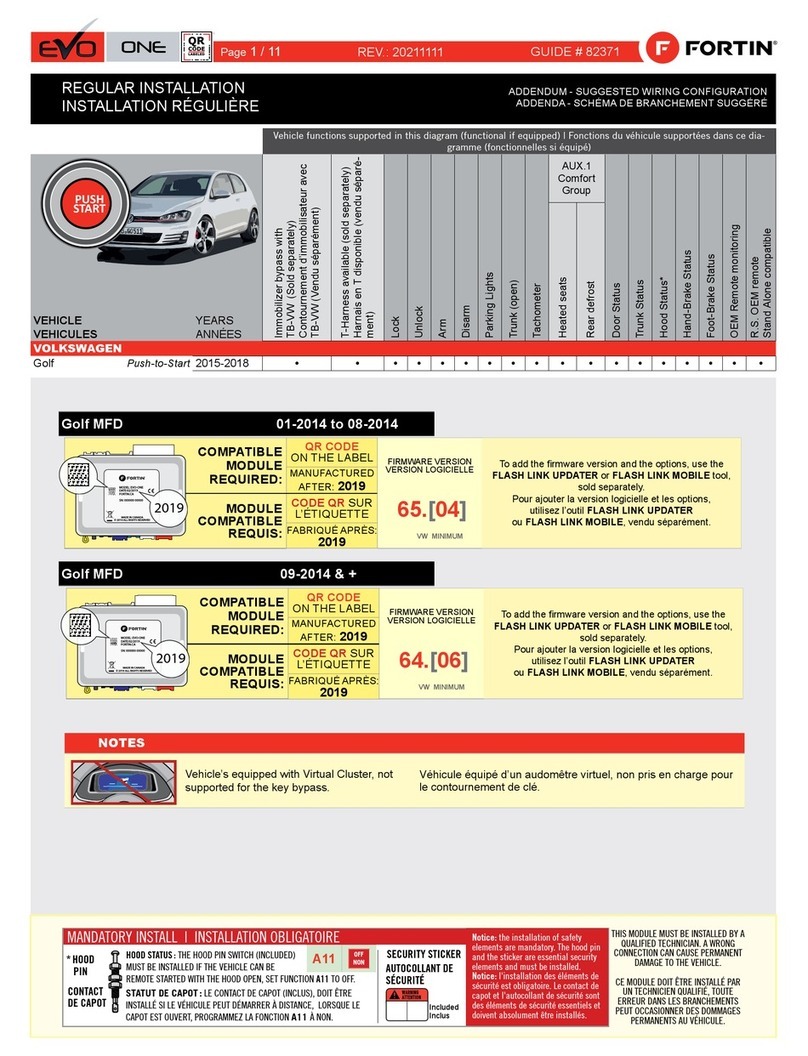
Fortin EVO ONE User manual

Fortin

Fortin EVO ONE User manual
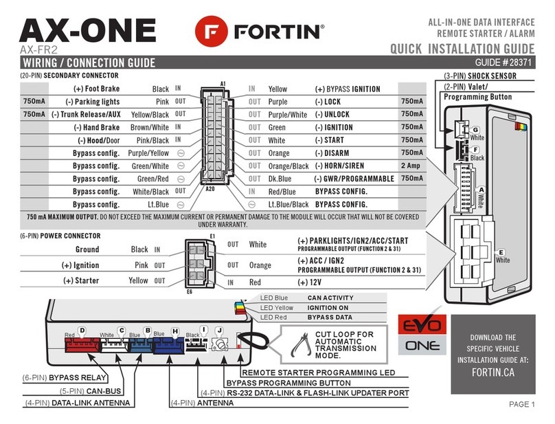
Fortin AX-ONE User manual

Fortin

Fortin AX-ONE User manual

Fortin EVO-ONE User manual

Fortin

Fortin EVO-ONE User manual
Fortin EVO-ALL User manual

Fortin

Fortin EVO-ALL User manual

Fortin EVO-ALL User manual

Fortin

Fortin EVO-ALL User manual

Fortin E400 RF642W User manual

Fortin

Fortin E400 RF642W User manual

Fortin EVO-ALL-411 User manual

Fortin

Fortin EVO-ALL-411 User manual

Fortin EVO-ALL User manual

Fortin

Fortin EVO-ALL User manual

Fortin EVO-ALL User manual

Fortin

Fortin EVO-ALL User manual

Fortin KEY-OVERRIDE-ALL User manual

Fortin

Fortin KEY-OVERRIDE-ALL User manual

Popular Remote Starter manuals by other brands
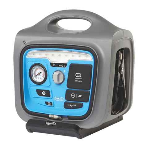
ring RPP160 instructions

ring

ring RPP160 instructions

Schumacher Instant Power IP-1825FL owner's manual
Schumacher

Schumacher Instant Power IP-1825FL owner's manual

Directed Electronics SmartStart 5000-series Quick reference install guide
Directed Electronics

Directed Electronics SmartStart 5000-series Quick reference install guide

Clifford Smart Remote Starter 2 owner's manual
Clifford

Clifford Smart Remote Starter 2 owner's manual

strex SP176 user manual

strex

strex SP176 user manual

Omega RS-3A Operating & installation instructions
Omega

Omega RS-3A Operating & installation instructions

CompuSTAR 2WAMR user guide

CompuSTAR

CompuSTAR 2WAMR user guide

King Tony Mighty Seven FA-1214 manual

King Tony

King Tony Mighty Seven FA-1214 manual
Schumacher IP-55 owner's manual

Schumacher

Schumacher IP-55 owner's manual
ULTRA PERFORMANCE 39010 manual

ULTRA PERFORMANCE

ULTRA PERFORMANCE 39010 manual
ULTIMATE SPEED UMAP 12000 A1 Operation and safety notes translation of the original instructions

ULTIMATE SPEED

ULTIMATE SPEED UMAP 12000 A1 Operation and safety notes translation of the original instructions

Toyota PT398-60080 installation guide

Toyota

Toyota PT398-60080 installation guide

Adventure Kings AKEP-LJS1000A 01 user manual

Adventure Kings

Adventure Kings AKEP-LJS1000A 01 user manual

AutoLoc KL400 User guide and installation manual

AutoLoc

AutoLoc KL400 User guide and installation manual

Chamberlain LiftMaster Professional Security+ 376LM quick guide
Chamberlain

Chamberlain LiftMaster Professional Security+ 376LM quick guide

Schumacher INSTANT POWER XJS4 owner's manual
Schumacher

Schumacher INSTANT POWER XJS4 owner's manual

SP tools SP61073 user manual

SP tools

SP tools SP61073 user manual
CompuSTAR 2WFMRS user guide

CompuSTAR

CompuSTAR 2WFMRS user guide

manuals.online logo
manuals.online logoBrands
  • About & Mission
  • Contact us
  • Privacy Policy
  • Terms and Conditions

Copyright 2025 Manuals.Online. All Rights Reserved.