manuals.online logo
Brands
  1. Home
  2. •
  3. Brands
  4. •
  5. Fortin
  6. •
  7. Remote Starter
  8. •
  9. Fortin EVO ALL User manual

Fortin EVO ALL User manual

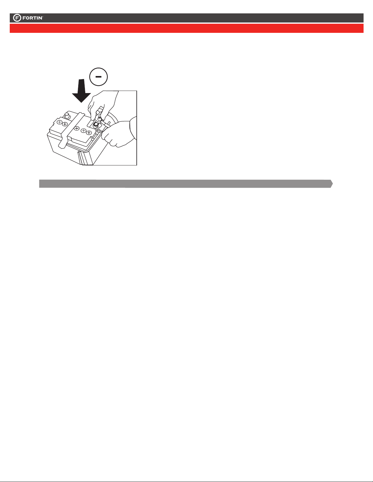
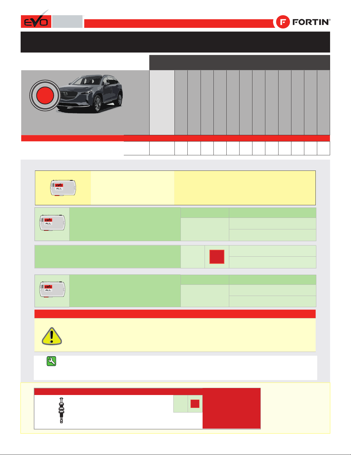
*HOOD PIN HOOD STATUS: THE HOOD PIN SWITCH MUST BE INSTALLED
IF THE VEHICLE CAN BE REMOTE STARTED WITH THE HOOD OPEN,
SET FUNCTION A11 TO OFF.
CONTACT
DE CAPOT
MANDATORY INSTALL | INSTALLATION OBLIGATOIRE Notice: the installation of safety
elements are mandatory. The hood pin
is an essential security element and
must be installed.
Notice: l'installation des éléments de
sécurité est obligatoire. Le contact de
capot est un élément de sécurité
essentiel et doit absolument être
installé.
THIS MODULE MUST BE INSTALLED BY A
QUALIFIED TECHNICIAN. A WRONG
CONNECTION CAN CAUSE PERMANENT
DAMAGE TO THE VEHICLE.
CE MODULE DOIT ÊTRE INSTALLÉ PAR
UN TECHNICIEN QUALIFIÉ, TOUTE
ERREUR DANS LES BRANCHEMENTS
PEUT OCCASIONNER DES DOMMAGES
PERMANENTS AU VÉHICULE.
STATUT DE CAPOT : LE CONTACT DE CAPOT, DOIT ÊTRE INSTALLÉ SI LE
VÉHICULE PEUT DÉMARRER À DISTANCE, LORSQUE LE CAPOT EST OUVERT,
PROGRAMMEZ LA FONCTION A11 À NON.
A11 OFF
NON
ADDENDUM - SUGGESTED WIRING CONFIGURATION
ADDENDA - SCHÉMA DE BRANCHEMENT SUGGÉRÉ
ALL REV.: 20211201
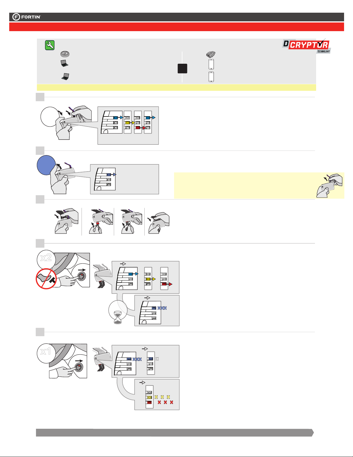
REGULAR INSTALLATION - 1 KEY PROGRAMMING
INSTALLATION RÉGULIÈRE - PROGRAMMATION 1 CLÉ
Parts required (Not included) Pièce(s) requise(s) (Non incluse(s))
1X 10 AMP Fuse 1X Fusible 10 AMP
Program bypass option:
Programmez l’option du contournement:
UNIT OPTION
OPTION UNITE DESCRIPTION
C1
OEM Remote status (Lock/Unlock)
monitoring
Suivi des status (Verrouillage/Déverrouil-
lage) de la télécommande d’origine
NOTES
THIS MODULE MUST BE INSTALLED
BY A QUALIFIED TECHNICIAN.
A WRONG CONNECTION CAN CAUSE
PERMANENT DAMAGE TO THE
VEHICLE.
CE MODULE DOIT ÊTRE INSTALLÉ PAR UN
TECHNICIEN QUALIFIÉ, TOUTE ERREUR DANS
LES BRANCHEMENTS PEUT OCCASIONNER DES
DOMMAGES PERMANENTS AU VÉHICULE.
Program bypass option
(Mandatory):
Programmez l’option du contournement
(Obligatoire):
UNIT OPTION
OPTION UNITE DESCRIPTION
D2
Unlock before / Lock after (Disarm OEM
alarm)
Déverrouille avant / Verrouille après
(Désarme l’alarme d’origine)
IF THE VEHICLE IS NOT EQUIPPED
WITH FUNCTIONAL HOOD PIN:
SI LE VÉHICULE N’EST PAS ÉQUIPÉ
D’UN CONTACT DE CAPOT FONCTIONNEL:A11 OFF
NON
Hood trigger (Output Status).
Contact de capot (état de sortie).
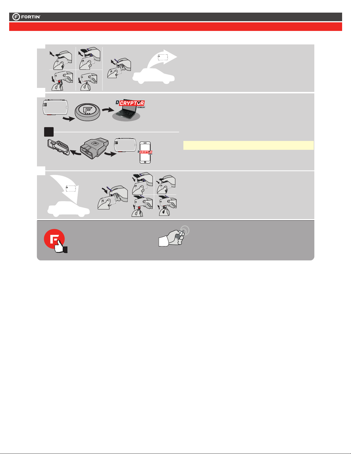
FIRMWARE VERSION
VERSION LOGICIELLE To add the rmware version and the options, use the FLASH LINK
UPDATER or FLASH LINK MOBILE tool, sold separately.
Pour ajouter la version logicielle et les options,
utilisez l’outil FLASH LINK UPDATER
ou FLASH LINK MOBILE, vendu séparément.
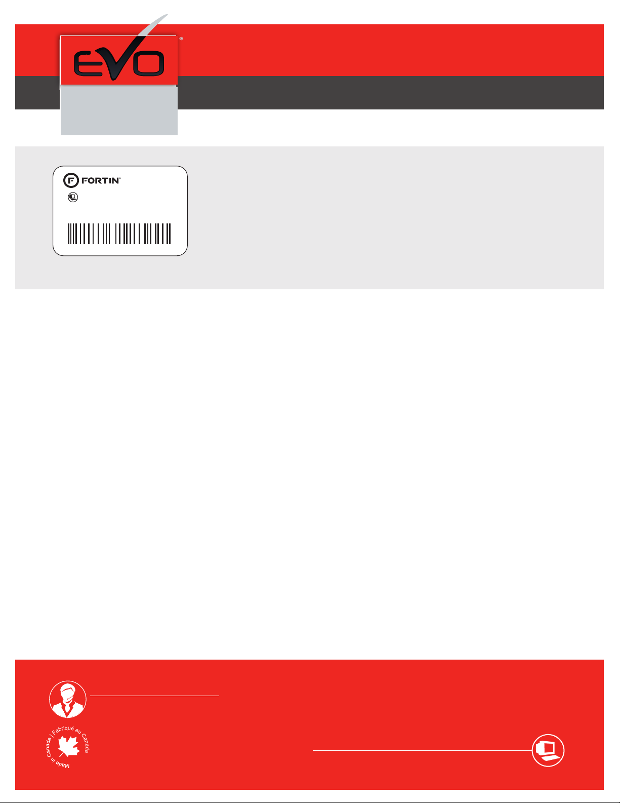
85.[11]
MINIMUM
GUIDE # 65541
Vehicle functions supported in this diagram (functional if equipped) | Fonctions du véhi-
cule supportées dans ce diagramme (fonctionnelles si équipé)
VEHICLE
VEHICULES
YEARS
ANNÉES
Immobilizer bypass
Contournement d’immobilisateur
Lock
Unlock
Arm
Disarm
Parking Lights
Tachometer
Door Status
Trunk Status
Hood Status protection remote
start
Hand-Brake Status
Foot-Brake Status
OEM Remote monitoring
MAZDA
CX9 Push-to-Start - Automatic transmission
Push-to-Start - transmission automatique 2016-2020 • ••••••••••••
PUSH
ST
ART
Page 1 / 9
This guide may change without notice. See www.fortin.ca for latest version.
Ce guide peut faire l’objet de changement sans préavis. Voir www.fortin.ca pour la récente version.
DESCRIPTION | DESCRIPTION
Under steering column, START-STOP unit
Sous la colonne de direction,
unité DÉMARRAGE
At parking lights switch
Au commutateur des feux de stationnement
DOOR LOCK DATA
()PARKING
LIGHTS
(-)PARKING
LIGHTS
Under steering column, START-STOP unit
Sous la colonne de direction,
unité DÉMARRAGE
(+)IGNITION2
(-)PTS
(+)IGNITION
(+)12V CAN LOW CAN HIGH
GROUND
(+)ACCES-
SORY
(+)IGNI-
TION3
Page 2 / 9
This guide may change without notice. See www.fortin.ca for latest version.
Ce guide peut faire l’objet de changement sans préavis. Voir www.fortin.ca pour la récente version.
Débranchez le borne
négative de la batterie du
véhicule.
Disconnect the (-) terminal of
the battery.
Effectuez les branchements
suivants.
Make the following
connections.
ATTENTION
1
2
3
Avant de débrancher un module, un ordinateur
ou une unité de contrôle d'un véhicule: il faut
toujours débrancher la borne négative de la
batterie du véhicule.
Dans ce véhicule, le module d'entrée sans clé
de l'usine est sensible aux interférences et
peut cesser de fonctionner si certaines
précautions ne sont pas prisses. Débrancher la
borne (-) de la batterie avant de déconnecter
le module de clé intélligente sous le volant
pour éviter de l'endommager.
Before disconnecting a module, a computer or a
control unit from a vehicle: Always disconnect
the negative terminal from the vehicle's battery.
In these vehicles, the factory keyless entry
module is sensitive to interference and may
cease to operate if some precautions are not
taken. Disconnect the (-) terminal of the battery
prior to disconnecting the connectors at the
smartkey module below the steering wheel to
avoid damage to the smartkey entry module.
Vehicle battery
Batterie du véhicule
Gently pull up the cover
of the steering column.
Tirez doucement sur le
couvercle de la colonne
de direction.
Right of Steering Column
Côté Droite de la
Colonne de direction
Left of Steering Column
Côté Gauche de la Colonne
de direction
4
Under the Steering Column
Sous la Colonne de direction
Unscrew.
Dévissez la vis. Onclip
Détachez
Onclip
Détachez
1 3
5
5
Under the Steering Column
Sous la Colonne de direction
Unscrew.
Dévissez la vis.
2
CONTINUED NEXT PAGE | CONTINUEZ À LA PAGE SUIVANTE
Page 3 / 9
This guide may change without notice. See www.fortin.ca for latest version.
Ce guide peut faire l’objet de changement sans préavis. Voir www.fortin.ca pour la récente version.
Yellow In A1
Purple In A2
Purple/White In A3
Green Out A4
White Out A5
Orange In A6
Orange/Black In A7
Dk.Blue In A8
Red/Blue In A9
Lt.Blue/Black A10
Black Out A11
Pink Out A12
Yellow/Black In A13
Brown/White Out A14
Pink/Black Out A15
Purple/Yellow A16
Green/White A17
Green/Red A18
White/Black A19
Lt.Blue A20
C5 Brown
C4 Gray/Black
C3 Gray
C2 Orange/Brown
C1 Orange/Green
D6 White/Red
D5 White/Blue
D4 White/Green
D3 Yellow/Red
D2 Yellow/Blue
D1 Yellow/Green
AC
D
AUTOMATIC TRANSMISSION WIRING CONNECTION | SCHÉMA DE BRANCHEMENT TRANSMISSION AUTOMATIQUE
Blue
Bleu Red/Black
Rouge/Noir Black
Noir
Blue
Bleu
Back view. 8-pin White
connector. Inside the
Parking lights switch.
Vue de dos. Connecteur
Blanc de 8-pins. À
l’intérieur du commutateur
des feux de stationnement.
Back view. 24-pin White
connector. Under steering
column, START-STOP unit.
Vue de dos. Connecteur Blanc
24-pins. Sous la colonne de
direction, unité DÉMARRAGE.
Back view. 32-pin White
connector. Under steering
column, START-STOP unit.
Vue de dos. Connecteur
Blanc 32-pins. Sous la
colonne de direction, unité
DÉMARRAGE.
110 23456789
192021 17
16 1415
32 31
13 12
18
11
27 25 24 23 2230 29 28 26
DOOR
LOCK
DATA
A20
(+)
IGNITION2
CUT
CUT
(-)PARKING
LIGHTS
(-)PARKING
LIGHTS
3 5 6 7 8142
D3
D1
OPTIONAL
FACULTATIF
(+)ACCES-
SORY
D2
Green
Vert
Yellow/Black
Jaune/Noir
Green/Red
Vert/Rouge
Gray
Gris
Pink
Rose
Lt.Blue
Bleu Pâle
Gray
Gris
14
A19 C4 C3
(-)PTS (+)12V (+)
IGNITION1
CAN
LOW
CAN
HIGH
(+)
STARTER
110 23456789
192021 17 16 15 13
12
18
11
24 23 22
3
OPTIONAL
FACULTATIF
GROUND
RS8 RS2 RS6/A1 RS4a
10 AMP
FUSE
FUSIBLE
10 AMP
CAN LOW
CAN HIGH
RS1
ACCESSORY
RS4a OUT (+)
IGNITION
RS6 IN/OUT (+)
Ground | Masse
(-)
RS1
12V BATTERY
RS2 IN
(+)
(+) Igni�on
A1
TRUNK RELEASEAT VEHICLE RS11OUT
(-)
STARTER
RS8 OUT (+)
DOOR LOCK DATA
OUT
(+)IGNITION2
(+)IGNITION2
D6
D4
(-)PARKING LIGHTS (COM)
(-)PARKING LIGHTS (NO)
(-)PARKING LIGHTS (NC)
Mandatory for
Idle mode
Requis pour le
mode continu
D2
(+)PARKING LIGHTS
PARKING LIGHTS
RS4 OUT (+) A16
IN
WITH | AVEC DATA-LINK:
ALWAYS REQUIRED
TOUJOURS REQUIS
NOT REQUIRED WITH
DATALINK
NON REQUIS EN
DATA-LINK
B
REMOTE
STARTER
DÉMARREUR
À DISTANCE
WITH | AVEC DATA-LINK:
Direct connection
Branchement directe
HOOD PIN
CONTACT CAPOT HOOD IN RS8
(-)
HAND BRAKE IN RS9
(-)
(+/-) IN RS12
TACHOMETER
F
OOT
B
RAKE
(+)
IN RS13
GROUND OUT WHILE RUNNING
(-) OUT RS14
TRUNK
(-)
IN RS15
DOOR
(-) IN RS16
UNLOCK
(-) OUT RS17
LOCK
(-) OUT RS18
A14
A12
A11
A8
A5
A4
A3
A2
(-) Start/Stop
(-) Hand Brake
(-/+) Tachometer
(+) Foot Brake
(-) Ground While Running
(-) Trunk Status
(-) Door Status
(-) Unlock
(-) Lock
A2
A3
A4
A5
A6
A7
A8
A9
A10
A11
A12
A13
A14
A15
A16
A17
A18
A19
A20
C5
C4
C3
C2
C1
D6
D5
D4
D3
D2
D1
A1
D5
C1
C2
C5
A18
A17
A15
A13
A10
A9
A7
A6
Page 4 / 9
This guide may change without notice. See www.fortin.ca for latest version.
Ce guide peut faire l’objet de changement sans préavis. Voir www.fortin.ca pour la récente version.
Rebranchez le pôle négative
de la batterie du véhicule.
CONTINUED NEXT PAGE | CONTINUEZ À LA PAGE SUIVANTE
Vehicle battery
Batterie du véhicule
Reconnect the (-) terminal of
the battery.
Page 5 / 9
This guide may change without notice. See www.fortin.ca for latest version.
Ce guide peut faire l’objet de changement sans préavis. Voir www.fortin.ca pour la récente version.
DCRYPTOR PROGRAMMING PROCEDURE | PROCÉDURE DE PROGRAMMATION AVEC DCRYPTOR
Parts required (not included) Pièces requises (non incluses)
1x FLASH LINK UPDATER,
1x FLASH LINK MANAGER
1x FLASH LINK MOBILE
1x FLASH LINK MOBILE APP
SOFTWARE | PROGRAMME
Smartphone Android or iOS with Internet connection
(Internet provider charges may apply)
Téléphone Intelligent Android ou iOS avec connection
Internet (des frais du fournisseur Internet peuvent s’appliquer)
OR
OU
Microsoft Windows Computer with Internet connection
Ordinateur Microsoft Windows avec connection Internet
1x1x
BEFORE PROGRAMMING SET THE UNIT OPTIONS AND SAVE. | AVANT LA PROGRAMMATION CONFIGURER LES OPTIONS DE L'UNITÉ ET SAUVEGARDER.
OFF
IGN ON
x2
PRESS
Press the Push-to-Start
button once to turn off the
ignition.
 will
turn off.
The BLUE LED
x1
PRESS
Appuyez 1 fois sur le
bouton démarrage (Push-
to-Start) pour éteindre
l'ignition.

s'éteint.
La DEL BLEUE
Do not press the brake
pedal. Press the
Push-to-Start button twice
to turn ON the ignition.
Ne pas appuyer sur la pédale
de frein. Appuyez 2 fois sur le
bouton démarrage
(Push-to-Start) pour allumer
l'ignition.
wait, attendre,
 The BLUE LED will
flash rapidly.
 The RED and YELLOW
LEDs will alternated.
 La DEL BLEUE clignotera
rapidement.
 La DEL ROUGE et
JAUNE alternent.
1
1
 The Blue, Red, Yellow
and Blue & Red LEDs will
alternatively illuminate.
 Les DELs Bleue, Rouge,
Jaune et Bleue & Rouge
illumineront alternativement.
 The Blue, Red and
Yellow LEDs will alternatively
illuminate.
 Les DELs Bleue, Rouge,
et Jaune illumineront
alternativement.
2
3
4
5
Connect the required
remaining harnesses.
Branchez les harnais
requis restants.
Release the programming
button when the Blue LED
is ON.
Relâchez le bouton de program-
mation quand la DEL Bleue est
allumée.
CONTINUED NEXT PAGE | CONTINUEZ À LA PAGE SUIVANTE
x1
HOLD
Press and hold the
programming button:
Connect the 4-PIN Data-link
harness (Black connector).
Appuyez et maintenir le bouton
de programmation enfoncé:
Branchez le harnais Data-Link à
4-Broches (connecteur Noir)
If the LED are not solid BLUE
disconnect the 4-PIN Data-link
harness (Black connector) and go
back to step1.
Si la DEL Bleue n’est pas allumée,
débranchez le harnais Data-Link à
4-Broches (connecteur Noir) et
retournez au début de l'étape 1.
LED may dier depending on the module casing.
L’apparence des DELS peuvent diérer selon le
boîtier du module.
RELEASE
ON BLUE
BLEU
FLASH
ALTERNATE
WAIT
IGNITION ON IGNITION OFF
OFF
FLASH RAPIDLY
Page 6 / 9
This guide may change without notice. See www.fortin.ca for latest version.
Ce guide peut faire l’objet de changement sans préavis. Voir www.fortin.ca pour la récente version.
KEY BYPASS PROGRAMMING PROCEDURE 2/2 | PROCÉDURE DE PROGRAMMATION CONTOURNEMENT DE CLÉ 2/2
EVO-ALL
Disconnect all the connectors and after
the Data-Link (4-pins) connector.
Débranchez tous les connecteurs et ensuite
le connecteur Data-Link (4-pins).
*Pièces requises (non incluses)
Use the tool:
FLASH LINK UPDATER or
FLASH LINK MOBILE
to visit the DCryptor menu.
Utilisez l'outil:
FLASH LINK UPDATER ou
FLASH LINK MOBILE
pour visiter le menu DCryptor.
*Parts required (not included)
FLASH LINK UPDATER*
FLASH LINK MOBILE*
FLASH LINK MANAGER*
SOFTWARE | PROGRAMME
Microsoft Windows
Computer with
Internet connection*
Ordinateur Microsoft
Windows avec
connection Internet*
VEHICLE'S OBDII
CONNECTOR
CONNECTEUR OBDII
DU VÉHICULE
OR
OU
Smartphone*
(Internet provider
charges
may apply)
Téléphone
Intelligent*
(des frais du
fournisseur
Internet peuvent
s’appliquer)
REMOTE STARTER / ALARM VERIFICATION
PROCEDURE | PROCÉDURE DE VÉRIFICATION
DU DÉMARREUR À DISTANCE / ALARME
Test the remote starter. Remote start the vehicle.
Testez le démarreur à distance. Démarrez le véhicule
à distance.
The module is now programmed.
Le module est programmé.
AFTER DCRYPTOR PROGRAMMING COMPLETED
Go back to the vehicle and reconnect the 4-Pin (Data-Link)
connector and after, all the remaining connector.
APRÈS LA PROCÉDURE DE PROGRAMMATION
DCRYPTOR COMPLETÉE : retournez au véhicule et
rebranchez le connecteur 4-pins (Data-Link)
et après, tous les connecteurs du EVO-ALL.
EVO-ALL
6
7
8
Page 7 / 9
This guide may change without notice. See www.fortin.ca for latest version.
Ce guide peut faire l’objet de changement sans préavis. Voir www.fortin.ca pour la récente version.
REMOTE STARTER FUNCTIONALITY | FONCTIONNALITÉS DU DÉMARREUR À DISTANCE
Remote start the
vehicle.
Démarrez à
distance.
All doors must
be closed.
Toutes les
portes doivent
être fermées
Press the brake pedal.
The vehicle can now be
put in to gear and
driven.
If the Smart-Key is not detected
the vehicle will shut down.
Appuyez sur la pédale de
frein.
Vous êtes maintenant
prêt à embrayer et
prendre la route.
Si la clé intelligente n'est pas
détectées le véhicule s'éteindra.
Wait for the orange
led on the
Push-to-Start
button to turn on
and off twice.
Attendre que la
DEL orange du
bouton démarrage
s'allume et
s'éteingne deux
fois.
ON
x1
PRESS
FLASH
DO NOT PRESS THE
BRAKE PEDAL.
Press and release
the Push-to-Start
button once.
NE PAS APPUYER LA
PÉDALE DE FREIN.
Appuyez et relâchez
une fois le bouton
démarrage
(Push-to-Start.
Start
Enter the vehicle with the
SMART-KEY.
Entrez dans le véhicule
avec la clé intelligente
(SMART-Key) sur vous
UNLOCK
Unlock the doors
with either:
• The OEM remote
• The remote-starter
remote
Déverrouillez les
portes
avec soit:
• la télécommande
d'origine
• la télécomande du
démarreur à
distance
ENGINE
START
STOP
x2
Page 8 / 9
ALL
Service No : 000 102 04 2536
Date: xx-xx
INTERFACE MODULE
Made in Canada
PATENTS PENDING US: 2007-228827-A1
www.fortinbypass.com
HARDWARE VERSION
FIRMWARE VERSION
Module label | Étiquette sur le module
Notice: Updated Firmware and Installation Guides
Updated fi rmware and installation guides are posted on our web site on a regular
basis. We recommend that you update this module to the latest firmware and
download the latest installation guide(s) prior to the installation of this product.
Notice: Mise à jour microprogramme et Guides d’installations
Des mises à jour du Firmware (microprogramme) et des guides d’installation
sont mis en ligne régulièrement. Vérifiez que vous avez bien la dernière version
logiciel et le dernier guide d’installation avant l’installation de ce produit.
WARNING
The information on this sheet is provided on an (as is) basis with no representation or warranty of accuracy whatsoever.
It is the sole responsibility of the installer to check and verify any circuit before connecting to it. Only a computer safe
logic probe or digital multimeter should be used. FORTIN ELECTRONIC SYSTEMS assumes absolutely no liability or
responsibility whatsoever pertaining to the accuracy or currency of the information supplied. The installation in every case
is the sole responsibility of the installer performing the work and FORTIN ELECTRONIC SYSTEMS assumes no liability
or responsibility whatsoever resulting from any type of installation, whether performed properly, improperly or any other
way. Neither the manufacturer or distributor of this module is responsible of damages of any kind indirectly or directly
caused by this module, except for the replacement of this module in case of manufacturing defects. This module must be
installed by qualified technician. The information supplied is a guide only. This instruction guide may change without
notice. Visit www.fortinbypass.com to get the latest version.
MISE EN GARDE
L’information de ce guide est fournie sur la base de représentation (telle quelle) sans aucune garantie de précision et
d’exactitude. Il est de la seule responsabilité de l’installateur de vérifier tous les fils et circuits avant d’effectuer les connexions.
Seuls une sonde logique ou un multimètre digital doivent être utilisés. FORTIN SYSTÈMES ÉLECTRONIQUES n’assume
aucune responsabilité de l’exactitude de l’information fournie. L’installation (dans chaque cas) est la responsabilité de
l’installateur effectuant le travail. FORTIN SYSTÈMES ÉLECTRONIQUES n’assume aucune responsabilité suite à
l’installation, que celle-ci soit bonne, mauvaise ou de n’importe autre type. Ni le manufacturier, ni le distributeur ne se
considèrent responsables des dommages causés ou ayant pu être causés, indirectement ou directement, par ce module,
excepté le remplacement de ce module en cas de défectuosité de fabrication. Ce module doit être installé par un technicien
qualifié. L’information fournie dans ce guide est une suggestion. Ce guide d’instruction peut faire l’objet de changement
sans préavis. Consultez le www.fortinbypass.com pour voir la plus récente version.
Copyright © 2006-2018, FORTIN AUTO RADIO INC ALL RIGHTS RESERVED PATENT PENDING
TECH SUPPORT
Tél: 514-255-HELP (4357)
1-877-336-7797
ADDENDUM GUIDE WEB UPDATE | MISE À JOUR INTERNET
www.fortinbypass.com
EVO-ALL
Page 9 / 9

Other manuals for EVO ALL

34

Other Fortin Remote Starter manuals

Fortin RM912 User manual

Fortin

Fortin RM912 User manual

Fortin EVO ALL User manual

Fortin

Fortin EVO ALL User manual

Fortin FSA-206 User manual

Fortin

Fortin FSA-206 User manual

Fortin INT-SL User manual

Fortin

Fortin INT-SL User manual

Fortin GM-SL2 User manual

Fortin

Fortin GM-SL2 User manual

Fortin EVO-CAN User manual

Fortin

Fortin EVO-CAN User manual

Fortin EVO-ONE User manual

Fortin

Fortin EVO-ONE User manual

Fortin FTX84-1W User manual

Fortin

Fortin FTX84-1W User manual

Fortin Evo Ride User manual

Fortin

Fortin Evo Ride User manual

Fortin EVO-ONE RFK912 User manual

Fortin

Fortin EVO-ONE RFK912 User manual

Fortin E400 RF442W User manual

Fortin

Fortin E400 RF442W User manual

Fortin EVO-START User manual

Fortin

Fortin EVO-START User manual

Fortin EVO-ONE FTX25 User manual

Fortin

Fortin EVO-ONE FTX25 User manual

Fortin ORBITF2400 User manual

Fortin

Fortin ORBITF2400 User manual

Fortin ANT-FMH-2W User manual

Fortin

Fortin ANT-FMH-2W User manual

Fortin 2ACKU-DL1004 User manual

Fortin

Fortin 2ACKU-DL1004 User manual

Fortin FTX-64-2W User manual

Fortin

Fortin FTX-64-2W User manual

Fortin EVO ALL User manual

Fortin

Fortin EVO ALL User manual

Fortin EVO-CAN User manual

Fortin

Fortin EVO-CAN User manual

Fortin TB-TOYOTA User manual

Fortin

Fortin TB-TOYOTA User manual

Fortin GM-SL User manual

Fortin

Fortin GM-SL User manual

Fortin EVO-ONE User manual

Fortin

Fortin EVO-ONE User manual

Fortin EVO ONE User manual

Fortin

Fortin EVO ONE User manual

Fortin EVO-ONE RFK942 User manual

Fortin

Fortin EVO-ONE RFK942 User manual

Popular Remote Starter manuals by other brands

Audiovox APS687 - Car Prestige Remote Start installation manual

Audiovox

Audiovox APS687 - Car Prestige Remote Start installation manual

idatastart COM-IDS(RS)-BZ3-[CMBMXA0]-EN install guide

idatastart

idatastart COM-IDS(RS)-BZ3-[CMBMXA0]-EN install guide

Craftsman CMXCESM14143 instruction manual

Craftsman

Craftsman CMXCESM14143 instruction manual

Autostart AS-6450VTW-FM Quick installation guide

Autostart

Autostart AS-6450VTW-FM Quick installation guide

Auto Mate 4214A owner's guide

Auto Mate

Auto Mate 4214A owner's guide

Autostart As2373twv user guide

Autostart

Autostart As2373twv user guide

Omegalink Omega PL1 install guide

Omegalink

Omegalink Omega PL1 install guide

Autostart ASRS-7505 quick start guide

Autostart

Autostart ASRS-7505 quick start guide

Tack life KP120 user manual

Tack life

Tack life KP120 user manual

Nordic Start NTW-2200 user guide

Nordic Start

Nordic Start NTW-2200 user guide

Autostart AS-1755V user guide

Autostart

Autostart AS-1755V user guide

Autostart Two-way Led Manual Transmission Remote Starter and Full Alarm... user guide

Autostart

Autostart Two-way Led Manual Transmission Remote Starter and Full Alarm... user guide

Autostart AS-6265iSH user guide

Autostart

Autostart AS-6265iSH user guide

Autostart ASRS-3520 quick start guide

Autostart

Autostart ASRS-3520 quick start guide

Auto Page RS-610 Operation manual

Auto Page

Auto Page RS-610 Operation manual

Autostart AS-2350vTW-FM Quick installation guide

Autostart

Autostart AS-2350vTW-FM Quick installation guide

Autostart AS-6205i SH Quick installation guide

Autostart

Autostart AS-6205i SH Quick installation guide

Auto Page C3-RS-625 installation manual

Auto Page

Auto Page C3-RS-625 installation manual

manuals.online logo
manuals.online logoBrands
  • About & Mission
  • Contact us
  • Privacy Policy
  • Terms and Conditions

Copyright 2025 Manuals.Online. All Rights Reserved.