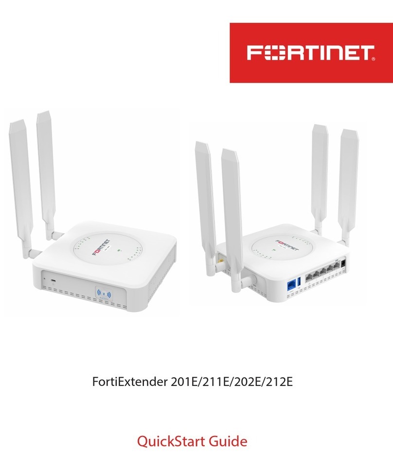
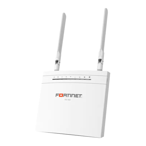
Fortinet FEX-511F User manual

QuickStart Guide
FortiExtender 511F
FortiExtender-511F-QuickStart.indd 1FortiExtender-511F-QuickStart.indd 1 7/22/2021 6:21:37 PM7/22/2021 6:21:37 PM

July 22, 2021
Copyright © 2021 Fortinet, Inc. All rights reserved. Fortinet®, FortiGate®,
FortiCare®and FortiGuard®, and certain other marks are registered trademarks
of Fortinet, Inc., in the U.S. and other jurisdictions, and other Fortinet names
herein may also be registered and/or common law trademarks of Fortinet.
All other product or company names may be trademarks of their respective
owners. Performance and other metrics contained herein were attained in
internal lab tests under ideal conditions, and actual performance and other
results may vary. Network variables, dierent network environments and
other conditions may aect performance results. Nothing herein represents
any binding commitment by Fortinet, and Fortinet disclaims all warranties,
whether express or implied, except to the extent Fortinet enters a binding
written contract, signed by Fortinet’s General Counsel, with a purchaser
that expressly warrants that the identied product will perform according
to certain expressly-identied performance metrics and, in such event, only
the specic performance metrics expressly identied in such binding written
contract shall be binding on Fortinet. For absolute clarity, any such warranty
will be limited to performance in the same ideal conditions as in Fortinet’s
internal lab tests. In no event does Fortinet make any commitment related to
future deliverables, features or development, and circumstances may change
such that any forward-looking statements herein are not accurate. Fortinet
disclaims in full any covenants, representations, and guarantees pursuant
hereto, whether express or implied. Fortinet reserves the right to change,
modify, transfer, or otherwise revise this publication without notice, and the
most current version of the publication shall be applicable.
FortiExtender-511F-QuickStart.indd 2FortiExtender-511F-QuickStart.indd 2 7/22/2021 6:21:37 PM7/22/2021 6:21:37 PM
QuickStart Guide
Register for Support
Register your Fortinet product to receive:
• Technical Support
• New product features
• Protection from new threats
Vous devez enregistrer le produit pour recevoir:
• Support technique
• Nouvelles fonctionnalités du produit
• Protection contre de nouvelles menaces
La reistrazione ti permette di usufruire di:
• Supporto Tecnico
• Nuove funzionalita
• Protezione dalle ultime minacce
Debe registrar el producto para recibir:
• Apoyo técnico
• Nuevas funcionalidades del producto
• Protección contra ataques
登録のお願い
本日、フォーティネット製品の登録をしてください。
登録すると次のメリットがあります。
テクニカルサポート • 新機能の追加 • 新しい脅威への防御
请马上注册
您的飞塔产品
您在注册以后才能得到技术支持、新产品特点信息、最新威胁防护
https://support.fortinet.com
Toll free: 1 866 648 4638
Phone: 1 408 486 7899
Fax: 1 408 235 7737
Email: register@fortinet.com
FortiExtender-511F-QuickStart.indd 3FortiExtender-511F-QuickStart.indd 3 7/22/2021 6:21:37 PM7/22/2021 6:21:37 PM
Packing List
5G/LTE/GNSS All-in-One Antennas
QuickStart Guide
Mounting Kit
Anchors and Screws
Drill Template Sticker
Rubber Feet
FortiExtender-511F
4
FortiExtender-511F-QuickStart.indd 4FortiExtender-511F-QuickStart.indd 4 7/22/2021 6:21:38 PM7/22/2021 6:21:38 PM

5
Product Description
FortiExtender 511F is a wireless Internet WAN connection device which provides a Sub-6
GHz 5G wireless connection, with a maximum downlink speed of 5 Gbps and a maximum
uplink speed of 650 Mbps in NSA mode and a maximum downlink speed of 4.2 Gbps and a
maximum uplink speed of 450 Mbps in SA mode.
When 5G connection is unavailable, it provides 4G LTE CAT 20 connection with a maximum
downlink speed of 2 Gbps and a maximum uplink speed of 200 Mbps.
FEX-511F is able to provide one 1G SFP connection, one 1G RJ-45 wired WAN connection, and
four 1G LAN connections.
Model Modem
FEX-511F 5G Sub-6 module pre-installed.
Notes:
• 5G Sub-6 module (NSA: 5.0 Gbps downlink and 650 Mbps uplink; SA: 4.2 Gbps
downlink and 450 Mbps uplink. Region: worldwide).
• FEX-511F only support MicroSIM (3FF) SIM cards, which are not included. You
must purchase your own SIM cards.
FortiExtender-511F-QuickStart.indd 5FortiExtender-511F-QuickStart.indd 5 7/22/2021 6:21:38 PM7/22/2021 6:21:38 PM

6
Ports, LEDs, and Buttons
LAN (1–4) Ports & LEDs
Port 4 is PoE PD LAN (802.3at)
USB 2.0 Port
Console Port
Note: To access the device from
its console port, you must set
the baud rate to 115200.
SFP Port & LED WAN Port & LED
12V/2A Input (optional)
(Use 12V/2A power adapter with ID 2.1 mm plug.)
FortiExtender-511F-QuickStart.indd 6FortiExtender-511F-QuickStart.indd 6 7/22/2021 6:21:38 PM7/22/2021 6:21:38 PM

7
Kensington Lock Slot Bluetooth LED
Bluetooth Button SIM Slot Cover Screw
SIM Slot Cover
Reset/Default Button
FortiExtender-511F-QuickStart.indd 7FortiExtender-511F-QuickStart.indd 7 7/22/2021 6:21:39 PM7/22/2021 6:21:39 PM

8
LED Behavior and Description
SFP • Green Steady: 1 G network connection.
• Green Flashing: 1 G network activity.
• OFF: No network connection.
RJ45 Network LEDs • Green Steady: 1G network connected.
• Green Flashing: 1G network activity.
• Amber Steady: 100M network connected.
• Amber Flashing: 100M network activity.
• O: No network connection.
Bluetooth LED • Green Steady: Bluetooth conguration window is open
(upon pressing the Bluetooth button. It closes in 30 seconds
if no conguration is performed.)
• Blue Flashing: Bluetooth conguration is in progress.
• Blue Steady: Bluetooth conguration is completed. The LED
turns o in 5 seconds.
• O: No Bluetooth conguration is allowed.
LED Behavior
Button Operating Instructions
Reset/Default Button • Press and hold for less than 5 seconds: Reset/Reboot the
device.
• Press and hold for more than 5 seconds: Restore the
device to its factory default settings.
Bluetooth Button • Press and hold for less than 5 seconds: Ignored.
• Press and hold for more than 5 seconds: Turns on
Bluetooth LED, and opens Bluetooth conguration
window. (Note: The“window” closes if no Bluetooth
conguration activity occurs within 30 seconds. Re-
pressing the button has no eect while Bluetooth
conguration is in progress or if it is completed within 5
minutes.)
Control Button Usage
FortiExtender-511F-QuickStart.indd 8FortiExtender-511F-QuickStart.indd 8 7/22/2021 6:21:39 PM7/22/2021 6:21:39 PM

9
5G Module RF Connectors
RF Connectors & System LEDs
Main MIMO1 MIMO2 Diversity/GNSS
LTE/5G Signal Level 4
LTE/5G Signal Level 3
LTE/5G Signal Level 2
LTE/5G Signal Level 1
LTE/5G
Power LTE Mode 5G Mode Management FortiSASE/LAN Extension
FortiExtender-511F-QuickStart.indd 9FortiExtender-511F-QuickStart.indd 9 7/22/2021 6:21:39 PM7/22/2021 6:21:39 PM

10
LED Description
Power • Green Steady: System has booted up and is working properly.
• Green Flashing: System is booting up.
• Amber: System is in error state.
• OFF: System is powered o.
LTE Mode • Green: System is running in LTE connection mode.
• OFF: System is not in LTE mode.
5G Mode • Blue: System is running in 5G connection mode.
• OFF: System is not in 5G mode.
Management • Blue Steady: System is managed by FortiGate or
FortiExtender Cloud.
• Blue Flashing: System is connecting to a managing device.
• OFF: System is running in stand-alone mode.
FortiSASE/LAN
Extension
• Blue Steady: System is connected to FortiSASE/LAN
Extension.
• Blue Flashing (at one-second intervals): System is connecting
to FortiSASE/LAN Extension.
• Blue Flashing Rapidly (at less-than-one-second intervals):
System is experiencing an error in connecting to FortiSASE/
LAN Extension.
• OFF: System is not congured for FortiSASE/LAN Extension.
Bluetooth • Green: Bluetooth conguration window opens upon
pressing the Bluetooth button. It closes in 30 seconds if no
conguration occurs.
• Blue Flashing: Bluetooth conguration is in progress.
• Blue Steady: Bluetooth conguration is completed. The LED
turns o in 5 seconds.
• OFF: No Bluetooth conguration is allowed.
The following tables describe the use of RF connectors and the system LEDs on top of the
FEX-511F casing.
FortiExtender-511F-QuickStart.indd 10FortiExtender-511F-QuickStart.indd 10 7/22/2021 6:21:39 PM7/22/2021 6:21:39 PM

11
LEDs Description
5G/LTE • Blue Steady: 5G module connected to carrier in 5G and
works properly.
• Green Steady: 5G module is connected to wireless carrier in
LTE mode and works properly.
• Green Flashing: 5G module is booting up and connecting to
wireless carrier.
• Green Rapid Flashing: 5G module is detected, but is
experiencing SIM or rmware error.
• OFF: 5G module is not detected.
5G/LTE Signal
Strength LEDs
(Blue=5G; Green=LTE)
• 1 On: < 25%.
• 1 & 2 On : 25% - 50%.
• 1, 2 & 3 On: 50% - 75%.
• 1, 2, 3, & 4 On: > 75%.
FortiExtender-511F-QuickStart.indd 11FortiExtender-511F-QuickStart.indd 11 7/22/2021 6:21:39 PM7/22/2021 6:21:39 PM

12
Wall Mounting Holes
Wall Hanging Slots
SIM Slot Cover
Screw
Rubber Feet Slots
FortiExtender-511F-QuickStart.indd 12FortiExtender-511F-QuickStart.indd 12 7/22/2021 6:21:40 PM7/22/2021 6:21:40 PM

1Basic Connections
1. Insert one end of an Ethernet cable into the LAN 4/PoE PD port on the device.
2. Insert the other end of the Ethernet cable into the PoE LAN port of your FortiGate
appliance, or to a WAN port of your FortiGate through a power injector. Ensure that the
FortiGate interface provides DHCP server service to issue an IP address to FortiExtender
when connected to LAN Port 4 of FortiExtender.
3. Optionally, if you are not using PoE, connect the device to a power outlet using a
power adapter.
LAN/PoE Internet
Warning:
You must provide adequate grounding to the PoE injector of the FortiExtender unit, if
required, in compliance with your local electrical code or regulations.
This device complies with IEEE 802.3af/at PoE specication. Do not use a PoE
injector that is not IEEE 802.3af/at compliant as it might damage your device.
13
Optional Power
Connection
FortiExtender-511F-QuickStart.indd 13FortiExtender-511F-QuickStart.indd 13 7/22/2021 6:21:40 PM7/22/2021 6:21:40 PM

14
Assembly
2
1. Remove the dust cover that protects the SIM sockets.
2. Insert your MicroSIM (3FF) SIM card(s) into the SIM socket(s).
3. Observe the following guidelines:
• If installing one SIM card, you can insert the card into either SIM socket.
• If installing two SIM cards, use SIM1 as the primary socket and SIM2 as the
secondary.
4. Insert the SIM card(s) into the SIM socket(s), making sure that the card is facing down
with the cut corner on the left. (If necessary, press the card again to remove it.)
5. Replace the cover, and then attach the antennas.
FortiExtender-511F-QuickStart.indd 14FortiExtender-511F-QuickStart.indd 14 7/22/2021 6:21:40 PM7/22/2021 6:21:40 PM

15
IP Conguration
3
After you have connected the FortiExtender network interfaces, the device automatically
attempts to obtain an IP address from a DHCP server. If you do not use DHCP, you can
congure a static IP address.
To congure a static IP address:
1. Use an Ethernet cable to connect one of the LAN ports to the Ethernet port of your
computer.
2. Set the computer Ethernet port to DHCP mode, and connect it to port1, port2, or port3.
3. Open your web browser and point to the default FortiExtender web GUI address:
http://192.168.200.99
4. In both the username and password elds, type admin and press the Enter key on
your keyboard. (Note: If you are logging in to the device for the rst time, you will be
prompted to change the default password. We strongly recommend that you change the
password right away.)
5. Go to Networking>Interface, where you’ll see all the system interfaces.
6. Select a desired interface, set it to “static”mode, congure the static IP address, and click
Save.
FortiExtender-511F-QuickStart.indd 15FortiExtender-511F-QuickStart.indd 15 7/22/2021 6:21:40 PM7/22/2021 6:21:40 PM

16
Installation
4
The FortiExtender device is designed for placement near a window (desk or wall mount) to
achieve the best 5G/LTE signal strength. Refer to the diagram below for proper placement
and mounting.
FortiExtender-511F-QuickStart.indd 16FortiExtender-511F-QuickStart.indd 16 7/22/2021 6:21:41 PM7/22/2021 6:21:41 PM

17
Place on top of a desk or at surface
1. Attach the rubber feet to the four corners on the bottom of the unit.
2. Place the unit on the desk or at surface.
3. Secure the unit in place with a Kensington lock.
4. Attach the antennas.
FortiExtender-511F-QuickStart.indd 17FortiExtender-511F-QuickStart.indd 17 7/22/2021 6:21:41 PM7/22/2021 6:21:41 PM

18
Hang on a wall
1. Peel o the drill template sticker, and stick it onto the wall in a desired location.
2. Use the template to mark and drill the pilot holes.
3. Insert the anchors into the holes.
4. Insert the screws into the anchors and tighten, leaving around a 5-mm gap between
the screw head and the wall.
5. Position the device so that the mounting holes line up with the screws.
6. Place the mounting slots over the screws and slide the device down until the screws
t into the slots.
Tip:
Use bear claw screws. The screw heads of bear claw screws have a built-in gap
that ts well with the hanging holes. You can purchase bear claw screws from a
local or online hardware store.
Fasten onto a wall
1. Peel o the drill template sticker, and stick it onto the wall in a desired location.
2. Use the template to mark and drill the pilot holes.
3. Insert the anchors into the holes.
4. Snap o the plastic cover over the LEDs on the front to reveal the long screw holes.
5. Insert the long screws through the device from front to back.
6. Insert the long screws into the anchors on the wall and tighten.
7. Replace the cover over the LEDs on the front. Refer to the illustrations on the next
page.
FortiExtender-511F-QuickStart.indd 18FortiExtender-511F-QuickStart.indd 18 7/22/2021 6:21:41 PM7/22/2021 6:21:41 PM

19
FortiExtender-511F-QuickStart.indd 19FortiExtender-511F-QuickStart.indd 19 7/22/2021 6:21:41 PM7/22/2021 6:21:41 PM

20
Cautions and Warnings
Environmental specications
Ambient operating temperature: 0°C to 40°C
Refer to specific Product Model Data Sheet for Environmental Specifications (Operating Temperature, Storage Temperature, Humidity, and Altitude)
Référez-vous à la Fiche Technique de ce produit pour les caractéristiques environnementales (Température de fonctionnement, température de stockage,
humidité et altitude).
Safety
Caution: This equipment is to be used in a Network Environment 0 per IECTR 62101. This product is connected only to PoE networks without routing to the
outside plant.
Attention: Ce matériel doit être utilisé dans un Environnement Réseau 0 d'après IECTR 62101. Ce produit est uniquement connecté aux réseaux PoE sans
routage vers une installation externe.
This product is intended to be supplied by a Listed Direct Plug-In Power Unit marked LPS or Class 2 and rated 12 Vdc, 2.5 A or by 54 Vdc from PoE source.
Le produit doit être alimenté par un bloc d’alimentation à courant continu homologué UL de 12 Vdc, 2.5 A nominal marqué LPS ou Class 2 ou par une source
d’alimentation par Ethernet de 54 Vdc (PoE).
FortiExtender-511F-QuickStart.indd 20FortiExtender-511F-QuickStart.indd 20 7/22/2021 6:21:41 PM7/22/2021 6:21:41 PM
Table of contents
Other Fortinet Extender manuals

Fortinet
Fortinet FEX-200F User manual

Fortinet
Fortinet FortiExtender 211E User manual

Fortinet
Fortinet FortiExtender 100B User manual

Fortinet
Fortinet FortiExtender 201E User manual

Fortinet
Fortinet FortiExtenderVehicle 212F User manual

Fortinet
Fortinet FortiExtender 40D User manual

Fortinet
Fortinet FortiExtender 311F User manual

Fortinet
Fortinet FortiExtenderVehicle 211F User manual

Fortinet
Fortinet FortiExtender 202E User manual