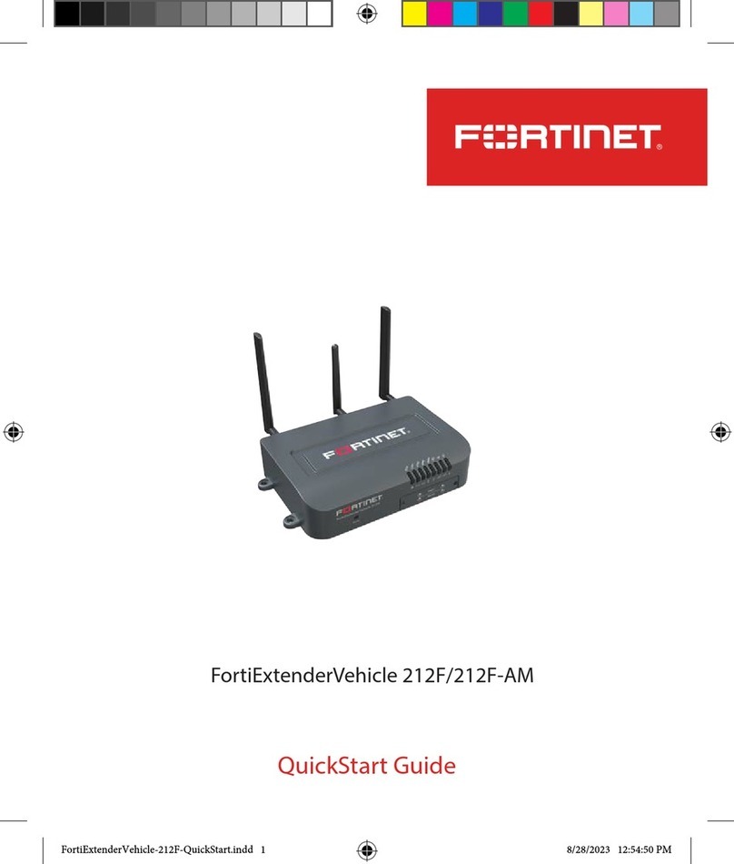
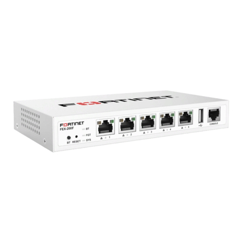
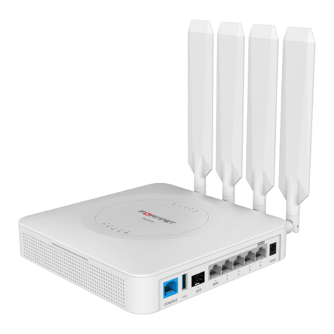
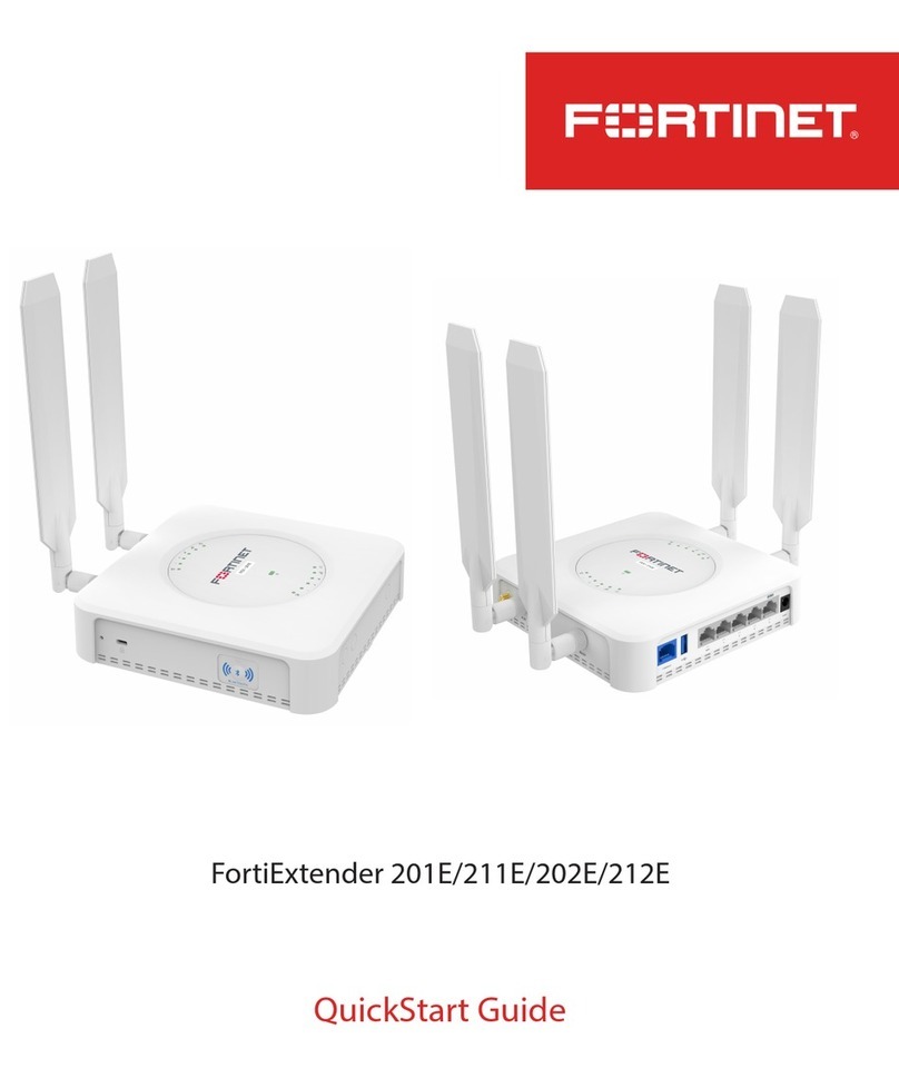
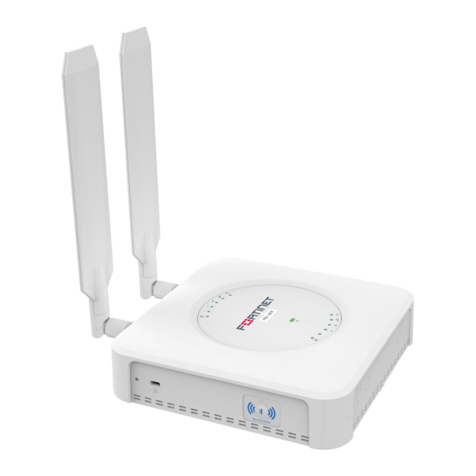
Fortinet FortiExtenderVehicle 211F User manual

QuickStart Guide
FortiExtenderVehicle 211F/211F-AM

QuickStart Guide
Register for Support
Register your Fortinet product to receive:
• Technical Support
• New product features
• Protection from new threats
Vous devez enregistrer le produit pour recevoir:
• Support technique
• Nouvelles fonctionnalités du produit
• Protection contre de nouvelles menaces
La reistrazione ti permette di usufruire di:
• Supporto Tecnico
• Nuove funzionalita
• Protezione dalle ultime minacce
Debe registrar el producto para recibir:
• Apoyo técnico
• Nuevas funcionalidades del producto
• Protección contra ataques
登録のお願い
本日、フォーティネット製品の登録をしてください。
登録すると次のメリットがあります。
テクニカルサポート • 新機能の追加 • 新しい脅威への防御
请马上注册
您的飞塔产品
您在注册以后才能得到技术支持、新产品特点信息、最新威胁防护
https://support.fortinet.com
Toll free: 1 866 648 4638
Phone: 1 408 486 7899
Fax: 1 408 235 7737
Email: register@fortinet.com
September 06, 2023
Copyright © 2023 Fortinet, Inc. All rights reserved. Fortinet®, FortiGate®,
FortiCare®and FortiGuard®, and certain other marks are registered trademarks
of Fortinet, Inc., in the U.S. and other jurisdictions, and other Fortinet names
herein may also be registered and/or common law trademarks of Fortinet.
All other product or company names may be trademarks of their respective
owners. Performance and other metrics contained herein were attained in
internal lab tests under ideal conditions, and actual performance and other
results may vary. Network variables, dierent network environments and
other conditions may aect performance results. Nothing herein represents
any binding commitment by Fortinet, and Fortinet disclaims all warranties,
whether express or implied, except to the extent Fortinet enters a binding
written contract, signed by Fortinet’s General Counsel, with a purchaser
that expressly warrants that the identied product will perform according
to certain expressly-identied performance metrics and, in such event, only
the specic performance metrics expressly identied in such binding written
contract shall be binding on Fortinet. For absolute clarity, any such warranty
will be limited to performance in the same ideal conditions as in Fortinet’s
internal lab tests. In no event does Fortinet make any commitment related to
future deliverables, features or development, and circumstances may change
such that any forward-looking statements herein are not accurate. Fortinet
disclaims in full any covenants, representations, and guarantees pursuant
hereto, whether express or implied. Fortinet reserves the right to change,
modify, transfer, or otherwise revise this publication without notice, and the
most current version of the publication shall be applicable.

5
Packing List
2 x WiFi & 1 x Bluetooth Antennas
QuickStart Guide
Anchors
FortiExtenderVehicle 211F
Drill Template Sticker
LTE/GNSS Vehicle Antenna (Optional)
Vehicle Power Adapter
Mounting Kit
Screws
SIM Card Adapter
4
Product Description
FortiExtenderVehicle 211F/211F-AM is a secure LTE wireless WAN extender device for
vehiclular and industrial applications. It has a CAT12 LTE/GNSS module, 2x2 2.4G/5G WiFi 5
(11ac Wave2), and BLE integrated in the device. It features one (1) GE WAN, four (4) GE LAN
RJ45 ports, one (1) USB 2.0, one (1) DB9 console, and an industrial digital I/O port of 1x opto
input and 1x relay NC/NO output. It provides 2x2 2.4/5GHz concurrent 802.11 a/b/g/n/ac
Wave2 WiFi up to 1200 Mbps and Bluetooth 5.0 communication.
FEV-211F-AM is for North America and supports Band 14 (FirstNet band). FEV-211F is for EU/
APAC countries and supports Band 28.
Model Modem
FEV-211F One (1) Sierra Wireless EM7565 LTE module.
FEV-211F-AM One (1) Sierra Wireless EM7511 LTE module.
Notes:
• EM7565 is a CAT12 module with LTE speed DL/UL=600/150Mbps and supports
GPS/GNSS/BeDou/Galileo navigation system. EM7565 supports Band 28, but does
not support Band 14 (FirstNet, emergency communication channel).
• EM7511 is a CAT12 module with LTE speeds of DL/UL=600/150Mbps and supports
GPS/GNSS/BeDou/Galileo navigation systems. EM7511 does not support Band 28,
but supports Band 14 (FirstNet, emergency communication channel).

6 7
Front Panel LEDs & Controls
Reset Button SIM Card Bay with Cover
Power/System LTE1 WiFi LAN 2.4G Bluetooth
WiFi LAN 5G
GPS/GNSS
WiFi WAN
LTE2
LEDs Behavior and Description
LTE2
(Green/Amber)
• Reserved for FEV-212F/FEV-212F-AM only.
GPS/GNSS
(Green/Amber)
• Green: GPS/GNSS locked with > 5 positioning satellites.
• Amber: GPS/GNSS locked with =< 5 positioning satellites.
• OFF: No GPS/GNSS.
WiFi WAN
(Green/Amber)
• Green Steady: 5G WiFi connected as WAN.
• Green Flashing: 5G WiFi WAN activity.
• Amber Steady: 2.4G WiFi connected as WAN.
• Amber Flashing: 2.4G WiFi WAN activity.
• OFF: No WAN connection.
WiFi LAN 2.4G
(Green)
• Green Steady: 2.4G WiFi connected as LAN.
• Green Flashing: 2.4G WiFi LAN activity.
• OFF: No 2.4G WiFi LAN.
WiFi LAN 5G
(Green)
• Green Steady: 5G WiFi connected as LAN.
• Green Flashing: 5G WiFi LAN activity.
• OFF: No 5G WiFi LAN.
Bluetooth
(Green/Amber)
• Green Steady: Bluetooth is ON.
• OFF: Bluetooth is OFF.
Amber LEDs
all on
• OS upgrade is in process.
Reset Button • Press and hold for less than ve (5) seconds to reset the system.
• Press and hold for ve (5) seconds or more to restore the system
to its default factory settings.
LEDs Behavior and Description
Power/System
(Green/Amber)
• Green Steady: System running normal.
• Green Flashing: Connected to wireless carrier.
• Amber Steady: System error.
• Amber Flashing: System boots up.
• OFF: No power.
LTE1
(Green/Amber)
• Green Steady: LTE1 ON with LTE signal level >= 50%.
• Green Flashing: LTE1 activity with LTE signal level >= 50%.
• Amber Steady: LTE1 ON with LTE signal level < 50%.
• Amber Flashing: LTE1 activity with LTE signal level < 50%.
• Green and Amber Both Flashing: LTE1 modem rmware
upgrade.
• OFF: LTE1 OFF.
LED Behavior

8 9
Digital I/O
USB 2.0 Port Power Button
7-36VDC input for
12V/24V Vehicle Battery
System
(Note: Use a power cable
with a 4-pin locked plug.)
Console Port
(Note: To access the device from
its console port, you must set
the baud rate to 115200.)
WiFi Antenna
LAN Ports 1-4 & LEDs
WAN Port & LED
WiFi Antenna
MAIN Antenna AUX Antenna Bluetooth Antenna
GNSS Antenna
Ports, LEDs, Buttons, and Antenna Connectors LED Behavior
Button Usage
Power Button • Press to lock: Power on.
• Press to release: Power o.
LEDs Behavior and Description
WAN Port LED • Green Steady: 1-Gb network connected.
• Green Flashing: 1-Gb network activity.
• Amber Steady: 100-Mb network connected.
• Amber Flashing: 100-Mb network activity.
• OFF: No network connection.
LAN Ports 1–4 LEDs • Green Steady: 1-Gb network connected.
• Green Flashing: 1-Gb network activity.
• Amber Steady: 100-Mb network connected.
• Amber Flashing: 100-Mb network activity.
• OFF: No network connection.
Digital I/O Denitions
Power Input Pin Denitions
Isolated Digital Input -
Isolated Digital Input +
(0V to 50V)
Relay Output - NO
Relay Output - COM
Relay Output - NC
Reserved
Power GND
Ignition Sense
Power +

Basic Connections
1. Press to release the power button to ensure that the device is in power-o state (the
power button is fully out).
2. Plug the cigarette lighter connector of the vehicle power adapter into the vehicle's
cigarette lighter socket.
3. Plug the 4-pin locked plug into the device power input socket, and press to lock the
power button to power on the device.
10
Mounting Holes 1
Battery Adapter Cable
11
To vehicle cigarette lighter
socket

12 13
Assembly
1. Unscrew the SIM socket dust cover fastening screws, and remove the dust cover.
2. When inserting your MicroSIM (3FF) SIM card(s) into the SIM socket(s), be sure to observe
the following guidelines:
• If installing one SIM card, you can insert the card into either SIM socket.
• If installing two SIM cards, use SIM1 as the primary socket and SIM2 as the secondary.
3. Insert the SIM card(s) into the SIM socket(s), making sure that the card is facing down
with the cut corner on the left. (If necessary, press the card again to remove it.)
4. Replace the SIM socket dust cover, tighten the dust cover screws, and attach the
antennas.
2
IP Conguration
Connect one of the LAN ports of the device to the Ethernet port of your computer, and the
device automatically attempts to obtain an IP address from the DHCP server. If you do not
use DHCP, you can congure a static IP address.
To congure a static IP address:
1. Use an Ethernet cable to connect one of the LAN ports to the Ethernet port of your
computer.
2. Set the computer Ethernet port to DHCP mode, and connect it to port1, port2, or port3.
3. Open your web browser and point to the default FortiExtender web GUI address:
http://192.168.200.99
4. In both the username and password elds, type admin and press the Enter key on
your keyboard. (Note: If you are logging into the device for the rst time, you will be
prompted to change the default password. We strongly recommend that you change the
password right away.)
5. Go to Networking>Interface, where you’ll see all the system interfaces.
6. Select a desired interface, set it to “static” mode, congure the static IP address, and click
Save.
3
Battery
12V-24V
Ground
(chassis)
Ground
(chassis)
Battery
(constant)
Accessory
(switched)
Ignition
(white)
Vehicle Fuse Panel
Ignition switch
ACC/ ON
Ground
(black)
Power
(red)
Inline fuse
(3A)
Power cable
Power Connection to Vehicle Fuse Panel
Note: UL/cUL Listing for US/Canada vehicle use does not cover use of products connected to
vehicle battery via DC cable/connector.

14 15
Installation
4
FortiExtenderVehicle 211F/211F-AM is designed for placement inside an automotive vehicle.
Refer to the following diagram for proper placement and mounting.
Fasten onto the wall of your vehicle
1. Peel o the drill template sticker, and stick it in a desired location on the wall.
2. Use the template to mark and drill the pilot holes.
3. If desired, insert the anchors into the holes.
4. Align the device with the holes or anchors.
5. Insert the screws into the holes or anchors and tighten.
Cautions and Warnings
Environmental specications
Ambient operating temperature: -40°C to 70°C.
Refer to specific Product Model Data Sheet for Environmental Specifications (Operating Temperature, Storage Temperature, Humidity, and Altitude).
Référez à la FicheTechnique de ce produit pour les caractéristiques environnementales (Température de fonctionnement, température de stockage,
humidité et l'altitude).
Safety
Warning: The equipment is intended for installation in Restricted Access Location.
Avertissement: Le matériel est conçu pour être installé dans un endroit où l’accès est restreint.
The equipment must be installed by skilled personnel.
L'équipement doit être installé par une personne qualifiée.
For use in a vehicle in US/Canada, a UL/CUL Listed (UL 2089) vehicle power adapter shall be used.
Pour usage dans un véhicule au États Unis/Canada, un adapteur de courrant homologué UL/CUL (UL 2089) doit être utilisé.
For use in a vehicle in US/Canada, this product is intended to be supplied by a listed vehicle power adapter marked Class 2 and rated 12Vdc, 2A or 24Vdc, 1A.
Pour usage dans un véhicule au États Unis/Canada, Ce produit est destiné à être alimenté par un adaptateur d'alimentation marqué Classe 2 et évalué
12Vdc, 2A ou 24Vdc, 1A.
This product is intended to be supplied by a listed power adapter marked LPS/PS2 or Class 2 and rated 12Vdc, 3A for indoor use only.
Ce produit est destiné à être alimenté par un adaptateur d'alimentation marqué LPS/PS2 ou Classe 2 et évalué 12Vdc, 3A pour usage intérieur seulement.

Regulatory Notices
For FortiExtenderVehicle 211F-AM only.
Federal Communication Commission (FCC)—USA
This device complies with Part 15 of the FCC Rules. Operation of the device is subject to the following two conditions:
1. This device may not cause harmful interference, and
2. This device must accept any interference received, including interference that may cause undesired operation.
This equipment has been tested and found to comply with the limits for a Class B digital device, pursuant to Part 15 of the FCC Rules.These limits are
designed to provide reasonable protection against harmful interference in residential installation. This equipment generates, uses, and can radiate radio
frequency energy, and if it is not installed and used in accordance with the instruction manual, it may cause harmful interference to radio communications.
However, there is no guarantee that interference will not occur in a particular installation.
If this equipment does cause harmful interference to radio or television reception, which can be determined by turning the equipment off and on, the user
is encouraged to try to correct the interference by one or more of the following measures:
• Reorient or relocate the receiving antenna.
• Increase the distance between the equipment and receiver.
• Connect the equipment to an outlet on a circuit different from that to which the receiver is connected.
• Consult the dealer or an experienced radio/TV technician for help.
WARNING: Any changes or modifications to this unit not expressly approved by the party responsible for compliance could void the user’s authority to
operate the equipment
This equipment complies with the FCC radiation exposure limits set forth for an uncontrolled environment. This equipment should be installed and
operated with a minimum distance 20 cm between the radiator and your body. This transmitter must not be co-located or operating in conjunction with
any other antenna or transmitter.
This device meets all the other requirements specified in Part 15E, Section 15.407 of the FCC Rules.
This radio transmitter (FCC:TVE-3317E142) has been approved by the FCC to operate with the antenna types listed below with the maximum permissible
gain and required antenna impedance for each antenna type indicated. Antenna types not included in this list, having a gain greater than the maximum
gain indicated for that type, are strictly prohibited for use with this device.
Antenna No. Manufacturer Part No. Antenna Type Connector Antenna Peak Gain
1 ADVANCED WIRELESS &
ANTENNA, INC.
A8EEE-000002 Dipole SMA 3.5 dBi for 2.4GHz (WLAN)
5.5 dBi for 5GHz
2 Master Wave
Technology Co., Ltd.
98619PRSX018 Dipole SMA 3.19 dBi for 2.4GHz (WLAN)
5.85 dBi for 5GHz
3 ADVANCED WIRELESS &
ANTENNA, INC.
A8EEE-000003 Dipole SMA 2.0 dBi for 2.4GHz(BLE)
Professional Installation Instructions
1. Installation personnel—This product is designed for specific application and needs to be installed by qualified personnel who has RF and related
regulatory knowledge. The general user shall not attempt to install or change the settings.
2. Installation location—The product shall be installed at a location where the radiating antenna can be kept 20 cm from the nearby person in normal
operation condition to meet the Regulatory RF exposure requirement.The installation applies to both indoor and outdoor locations.
3. External antenna(s)—Use only the antennas that have been approved by the manufacturer. Non-approved antennas may produce unwanted
spurious or excessive RF transmitting power that may lead to violation of the FCC/ISED limit and is prohibited.
4. Warning—Carefully select the installation location and ensure that the final output power does not exceed the limit set forth in relevant rules.
iolation of the rule could lead to serious federal penalty.
For FortiExtenderVehicle 211F-AM only.
Industry Canada Equipment Standard for Digital Equipment (ICES) – Canada
CAN ICES-003 (B) / NMB-003 (B)
16
This Class B digital apparatus complies with Canadian ICES-003.
Cet appareil numérique de la classe B est conforme à la norme NMB-003 du Canada.
Innovation, Science and Economic Development (ISED) – Canada
This device contains licence-exempt transmitter(s)/receiver(s) that comply with Innovation, Science and Economic Development Canada’s licence-exempt
RSS(s). Operation is subject to the following two conditions:
1. This device may not cause interference.
2. This device must accept any interference, including interference that may cause undesired operation of the device.
L’émetteur/récepteur exempt de licence contenu dans le présent appareil est conforme aux CNR d’Innovation, Sciences et Développement économique
Canada applicables aux appareils radio exempts de licence. L’exploitation est autorisée aux deux conditions suivantes:
1. L’appareil ne doit pas produire de brouillage;
2. L’appareil doit accepter tout brouillage radioélectrique subi, même si le brouillage est susceptible d’en compromettre le fonctionnement.
For product available in the USA/Canada market, only channel 1~11 can be operated. Selection of other channels is not possible.
Pour les produits disponibles aux États-Unis / Canada du marché, seul le canal 1 à 11 peuvent être exploités. Sélection d'autres canaux n'est pas possible.
Caution: The device for the band 5150-5250 MHz is only for indoor usage to reduce potential for harmful interference to co-channel mobile satellite
systems.
Attention: Le dispositif de la bande 5150-5250 MHz est réservé à un usage intérieur afin de réduire l'interférence nuisible potentielle aux systèmes mobiles
par satellite co-canal.
The maximum antenna gain permitted for devices in the bands 5250-5350 MHz and 5470-5725 MHz shall comply with the e.i.r.p. limit; and
Le gain maximal d’antenne permis pour les dispositifs utilisant les bandes 5250-5350 MHz et 5470-5725 MHz doit se conformer à la limite de p.i.r.e.;
The worst-case tilt angle(s) necessary to remain compliant with the e.i.r.p. elevation mask requirement set forth in Section 6.2.2(3) shall be clearly indicated.
Les pires angles d’inclinaison nécessaires pour rester conforme à l’exigence de la p.i.r.e. applicable au masque d’élévation, et énoncée à la section 6.2.2 3),
doivent être clairement indiqués.
The maximum antenna gain permitted for devices in the band 5725-5850 MHz shall be such that the equipment still complies with the e.i.r.p. limits
specified for point-to-point and non-point-to-point operation as appropriate.
Le gain maximal d’antenne permis (pour les dispositifs utilisant la bande 5725-5850 MHz)
doit se conformer à la limite de p.i.r.e. spécifiée pour l’exploitation point à point et non point à point, selon le cas.
This equipment complies with ISED radiation exposure limits set forth for an uncontrolled environment. This equipment should be installed and operated
with minimum distance 26cm between the radiator & your body.
Cet équipement est conforme aux limites d'exposition aux rayonnements ISED établies pour un environnement non contrôlé. Cet équipement doit être
installé et utilisé avec un minimum de 26cm de distance entre la source de rayonnement et votre corps.
This radio transmitter (IC: 7280B-3317E142) has been approved by ISED to operate with the antenna types listed below with the maximum permissible gain
and required antenna impedance for each antenna type indicated. Antenna types not included in this list, having a gain greater than the maximum gain
indicated for that type, are strictly prohibited for use with this device.
Le présent émetteur radio (IC: 7280B-3317E142) a été approuvé par ISED pour fonctionner avec les types d'antenne énumérés ci-dessous et ayant un gain
admissible maximal et l'impédance requise pour chaque type d'antenne. Les types d'antenne non inclus dans cette liste, ou dont le gain est supérieur au
gain maximal indiqué, sont strictement interdits pour l'exploitation de l'émetteur.
This device and its antennas(s) must not be co-located or operating in conjunction with any other antenna or transmitter except in accordance with IC
multi-transmitter product procedures.
Cet appareil et son antenne (s) ne doit pas être co-localisés ou fonctionnement en association avec une autre antenne ou transmetteur.
17
18
Antenna No. Manufacturer Part No. Antenna Type Connector Antenna Peak Gain
1 ADVANCED WIRELESS &
ANTENNA, INC.
A8EEE-000002 Dipole SMA 3.5 dBi for 2.4GHz (WLAN)
5.5 dBi for 5GHz
2 Master Wave
Technology Co., Ltd.
98619PRSX018 Dipole SMA 3.19 dBi for 2.4GHz (WLAN)
5.85 dBi for 5GHz
3 ADVANCED WIRELESS &
ANTENNA, INC.
A8EEE-000003 Dipole SMA 2.0 dBi for 2.4GHz(BLE)
Professional Installation Instruction
1. Installation personnel—This product is designed for specific application and needs to be installed by qualified personnel who has RF and related
rule knowledge. The general user shall not attempt to install or change the settings.
2. Installation location—The product shall be installed at a location where the radiating antenna can be kept 26cm from nearby person in normal
operation condition to meet Regulatory RF exposure requirement.The installation applies to both indoor and outdoor location.
3. External antenna(s)—Use only the antenna(s) that have been approved by the manufacturer.The non-approved antenna(s) may produce
unwanted spurious or excessive RF transmitting power that may lead to the violation of FCC/ISED limit and is prohibited.
4. Warning—Please carefully select the installation position and ensure that the final output power does not exceed the limit set forth in relevant
rules. Violation of the rule could lead to serious federal penalty.
Instructions d'installation professionnelle
1. Installation—Ce produit est conçu pour un usage spécifique et doit être installé par un personnel qualifié maîtrisant les radiofréquences et règle
similaires. L'utilisateur ne doit pas tenter d'installer ou de modifier les paramètres.
2. Emplacement d'installation—En usage normal, afin de respecter les exigences réglementaires concernant l'exposition aux radiofréquences, ce
produit doit être installe de façon à respecter une distance de 26cm entre l'antenne émettrice et. L'installation s'applique aux emplacements
intérieur et extérieur.
3. Antenne externe(s)—Utiliser uniquement l'antenne (s) approuvées par le fabricant. L'utilisation d'autres antennes peut conduire à un niveau de
rayonnement essentiel ou non essentiel dépassant les niveaux limites définis par FCC/ISED, ce qui est interdit.
4. Avertissement—Choisir avec soin la position d'installation et s'assurer que la puissance de sortie ne dépasse pas les limites en vigueur. La violation
de cette règle peut conduire à de sérieuses pénalités fédérales.
For FortiExtenderVehicle 211F only
European Conformity (CE)—EU
This is a Class B product. In a domestic environment, this product may cause radio interference, in which case the user may be required to take adequate
measures.
The product transmits within the frequency ranges and less than or equal to the power listed below:
Standard Frequency Range Max. Transmit Power
Bluetooth 2402–2480 MHz 10 dBm (EIRP)
WLAN 2.4 GHz: 2412–2472 MHz 20 dBm (EIRP)
WLAN 5 GHz: 5180–5240 MHz 23 dBm (EIRP)
WLAN 5 GHz: 5260–5320 MHz 23 dBm (EIRP)*
WLAN 5 GHz: 5500–5700 MHz 30 dBm (EIRP)*
WLAN 5 GHz: 5745–5825 MHz 14 dBm (EIRP)
WCDMA Band 1: 1920–1980 MHz (Uplink); 2110–2170 MHz (Downlink)
Band 8: 880–915 MHz (Uplink); 925–960 MHz (Downlink)
25.7 dBm (Conducted)
LTE Band 1: 1920–1980 MHz (Uplink); 2110–2170 MHz (Downlink)
Band 3: 1710–1785 MHz (Uplink); 1805–1880 MHz (Downlink)
Band 7: 2500–2570 MHz (Uplink); 2620–2690 MHz (Downlink)
Band 8: 880–915 MHz (Uplink); 925–960 MHz (Downlink)
Band 20: 832–862 MHz (Uplink); 791–821 MHz (Downlink)
Band 28: 703–748 MHz (Uplink); 758–803 MHz (Downlink)
Band 32: 1452–1496 MHz (Downlink)
Band 42: 3400–3600 MHz (Uplink); 3400–3600 MHz (Downlink)
Band 43: 3600–3800 MHz (Uplink); 3600–3800 MHz (Downlink)
Band 46: 5150–5925 MHz (Downlink)
25.7 dBm (Conducted)
Note: * Only with DFS bands certication.
This equipment should be installed and operated with a minimum distance 20 cm between the radiator & your body.
Simplied EU Declaration of Conformity
This declaration is only valid for Fortinet products (including combinations of software, firmware and hardware) provided by Fortinet or Fortinet’s
authorized partners to the end-customer directly for use within the EU or countries that have implemented the EU Directives and/or spectrum regulation.
Any Fortinet products not obtained directly from Fortinet or Fortinet’s authorized partners may not comply with EU Directives and Fortinet makes no
assurances for such products.
Български
Този продукт е в съответствие с Директива 2014/53/ЕС.
Česky
Tento produkt je v souladu se směrnicí 2014/53/EU.
Dansk
Dette produkt er i overensstemmelse med direktiv 2014/53/EU.
Deutsch
Dieses Produkt entspricht der Richtlinie 2014/53/EU.
19

Eesti
See toode vastab direktiivile 2014/53/EL.
English
This product is in compliance with Directive 2014/53/EU.
Español
Este producto cumple con la Directiva 2014/53/UE.
Ελληνική
Το προϊόν αυτό συμμορφώνεται με την Οδηγία 2014/53/ΕΕ.
Français
Ce produit est conforme à la Directive 2014/53/UE.
Hrvatski
Ovaj proizvod je u skladu s Direktivom 2014/53/EU.
Italiano
Questo prodotto è conforme alla Direttiva 2014/53/EU.
Latviski
Questo prodotto è conforme alla Direttiva 2014/53/EU.
Lietuvių
Šis gaminys atitinka direktyvą 2014/53/ES.
Malti
Dan il-prodott huwa konformi mad-Direttiva 2014/53/UE.
Magyar
Ez a termék megfelel a 2014/53/EU irányelvnek.
Nederlands
Dit product is in overeenstemming met Richtlijn 2014/53/EU.
Norsk
Dette produktet er i samsvar med direktiv 2014/53/EU.
Polski
Ten produkt jest zgodny z dyrektywą 2014/53/UE.
Português
Este produto está em conformidade com a Diretiva 2014/53/UE.
Rumunski
Acest produs este în conformitate cu Directiva 2014/53/UE.
Slovensky
Tento produkt je v súlade so smernicou 2014/53/EÚ.
Slovensko
Ta izdelek je v skladu z Direktivo 2014/53/EU.
Suomi
Tämä tuote on direktiivin 2014/53/EU mukainen.
Svenska
Denna produkt överensstämmer med direktiv 2014/53/EU.
Note: The full declaration of conformity for this product is available at the link below:
https://site.fortinet.com/ProductRegulatory/EU
20
Waste Electrical and Electronic Equipment (WEEE)
This symbol means that according to local laws and regulations your product and/or its battery shall
be disposed of separately from household waste. When this product reaches its end of life, take it to a
collection point designated by local authorities. Proper recycling of your product will protect human
health and the environment.
21
AT BE BG HR CY CZ DK
EE FI FR DE EL HU IE
IT LV LT LU MT NL PL
PT RO SK SI ES SE UK (NI)
The device is restricted to indoor use only when operating in the 5150 to 5350 MHz frequency range in the following countries:

For FortiExtenderVehicle 211F only
UK Conformity Assessed (UKCA) – United Kingdom
The product transmits within the frequency ranges and less than or equal to the power listed below:
Standard Frequency Range Maximum Transmit Power
Bluetooth 2402–2480 MHz 10 dBm (EIRP)
WLAN 2.4GHz: 2412–2472 MHz 20 dBm (EIRP)
WLAN 5GHz: 5180–5240 MHz 23 dBm (EIRP)
WLAN 5GHz: 5260–5320 MHz 23 dBm (EIRP)*
WLAN 5GHz: 5500–5700 MHz 30 dBm (EIRP)*
WLAN 5GHz: 5745–5825 MHz 14 dBm (EIRP)
WCDMA Band 1: 1920–1980 MHz (Uplink); 2110–2170 MHz (Downlink)
Band 8: 880–915 MHz (Uplink); 925–960 MHz (Downlink)
25.7 dBm (Conducted)
LTE Band 1: 1920–1980 MHz (Uplink); 2110–2170 MHz (Downlink)
Band 3: 1710–1785 MHz (Uplink); 1805–1880 MHz (Downlink)
Band 7: 2500–2570 MHz (Uplink); 2620–2690 MHz (Downlink)
Band 8: 880–915 MHz (Uplink); 925–960 MHz (Downlink)
Band 20: 832–862 MHz (Uplink); 791–821 MHz (Downlink)
Band 28: 703–748 MHz (Uplink); 758–803 MHz (Downlink)
Band 32: 1452–1496 MHz (Downlink)
Band 42: 3400–3600 MHz (Uplink); 3400–3600 MHz (Downlink)
Band 43: 3600–3800 MHz (Uplink); 3600–3800 MHz (Downlink)
Band 46: 5150–5925 MHz (Downlink)
25.7 dBm (Conducted)
Note: * Only with DFS bands certification.
This equipment should be installed and operated with minimum distance 20cm between the radiator & your body.
This product is in compliance with Statutory Instrument 1206 Radio Equipment Regulations 2017.
The full Declaration of Conformity for this product is available at the link below:
https://site.fortinet.com/ProductRegulatory/UK
The device is restricted to indoor use only when operating in the 5150 to 5350 MHz frequency range in the following countries:
UK (NI)
22 23
For Product License Agreement/EULA and Warranty Terms, visit:
https://www.fortinet.com/content/dam/fortinet/assets/legal/EULA.pdf

Fortinet.com
Fortinet Customer Service & Support
Create a support account, register and manage your products,
download updates, rmware images and release notes, and create
technical support tickets.
https://support.fortinet.com
Fortinet Document Library
Up-to-date versions of Fortinet publications for the entire family of
Fortinet products.
https://docs.fortinet.com
Training Services
Course descriptions, availability, schedules, and location of training
programs in your area.
https://training.fortinet.com
Technical Discussion Forums
Communicate with other customers and Fortinet partners about
Fortinet products, services, and conguration issues.
https://forum.fortinet.com
FortiGuard Threat Research and Response
Up-to-date information on vulnerabilities and threats, includes a
virus scanner, IP signature look-up, and web ltering tools.
https://fortiguard.com
This manual suits for next models
1
Table of contents
Other Fortinet Extender manuals

Fortinet
Fortinet FortiExtender 40D User manual

Fortinet
Fortinet FEX-200F User manual

Fortinet
Fortinet FortiExtender 211E User manual

Fortinet
Fortinet FortiExtender 201E User manual

Fortinet
Fortinet FortiExtenderVehicle 212F User manual

Fortinet
Fortinet FortiExtender 311F User manual

Fortinet
Fortinet FortiExtender 202E User manual

Fortinet
Fortinet FortiExtender 100B User manual

Fortinet
Fortinet FEX-511F User manual