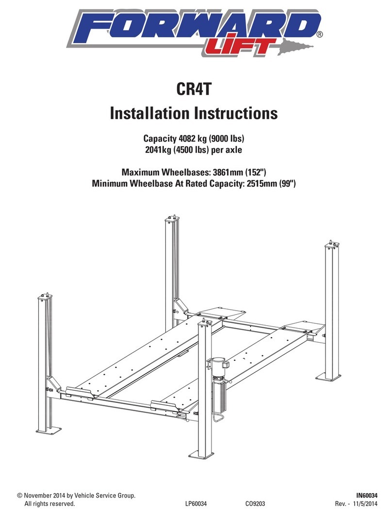
Forward Lift RSM4T User manual

RSM4T
Capacity 4082 kg (9000 lbs)
2041kg (4500 lbs) per axle
Maximum Wheelbases: 3861mm (152")
Minimum Wheelbase At Rated Capacity: 2515mm (99")
IN20534
Rev. C 9/10/2010
© September 2012 all rights reserved. CO8347
I
N
S
T
A
L
L
A
T
I
O
N
I
N
S
T
R
U
C
T
I
O
N
S
I
N
S
T
A
L
L
A
T
I
O
N
I
N
S
T
R
U
C
T
I
O
N
S
IMPORTANT Reference ANSI/ALI ALIS,
Safety Requirements for
Installation and Service of Automotive Lifts
before installing lift.

2
Fig. 1
YOU WILL NEED A MIN. OF
15’ CLEARANCE IN REAR
TO INSTALL “T” ROD
SPECIFICATIONS
At full rise.......................................... 1962mm (77-1/4”)
Baseplate to baseplate length .......... 4731mm (186-1/4”)
Baseplate to power unit width .......... 3277mm (129”)
Column height .................................. 2221mm (87-7/16”)
Width of runways.............................. 508mm (20”)
Height of runways............................. 127mm (5”)
Width between runways ................... 1000mm (39-3/8”)
Lift Capacity...................................... 4082 kg (9000 lbs)
4731mm (186-1/4”)
4070mm (160-1/4”)
4299mm (169-1/4”)
4500mm (177-3/16”)
772mm
(30-3/8”)
5337mm (210-1/8”)
508mm (20”)
2413mm (95”)
2718mm (107”)
3023mm (119”)
3277mm (129”)
2221mm (87-7/16”)
1962mm (77-1/4”)
127mm (5”)
508mm (20”)
1000mm (39-3/8”)
4191mm (165”)

3
Non-Power
Unit Column
(3 each)
Power
Unit Column
(1 each)
Right Runway
Your Lift Is Operated Hydraulically By
The Use Of An Electric Power Unit
Lock Lever
To Release Locks
From Latch Bars
Approach
Ramp
Assembly
(2 each)
Crossbeam Assembly
(2 each)
Base Plate
(1) On Each Column
Rear Of Lift
Left Runway Has Cylinder, Cables, Pull
Bar Assembly And Sheaves Underneath.
These Mechanical Components Are Used
To Raise And Lower The Lift. Cables Will
Also Be Routed Around Sheaves In
Crossbeam Assemblies And Up Through
All (4) Columns.
A Quick Overview Of Your Lift
Remember! Prepare A Location For Your Lift Before You Unload It From The Truck.
Location Should Be A Level Surface.
Safety
Wear work gloves, steel toed shoes, and safety glasses during the
installation of your lift.
IMPORTANT
Avoid drug or alcohol use that will impair your
ability to install or operate your lift.
DANGER
Improper installation or improper use of
your lift could cause serious injury or death. Read installation
instructions and owner's manual thoroughly before installing or
operating your lift.
Unloading And Unpacking Your Lift
The components for your lift are heavy. The runways for these
lifts weigh in excess of 182 kg (400 lbs) each. The preferred
method for unloading your lift is by forklift.
If a forklift is not available a minimum of (4) people able to lift 57
kg (125 lbs) EACH will be needed to unload and assemble your
lift.
57 kgs
125 lbs 57 kgs
125 lbs 57 kgs
125 lbs 57 kgs
125 lbs
CAUTION
Shipping bands around packages are under
extreme tension. Have everyone stand clear when cutting
shipping bands.
Note: Use personal protective equipment as required - Lift smart
using preferred methods. See your Lifting It Right Manual, page
23.
Examine each lift component as you unload it to check for
shipping damage.

4
Attention! Use 4 People
To Place Runways
57 kg
125 lbs
57 kg
125 lbs
57 kg
125 lbs
57 kg
125 lbs
Openings In Columns
Fach Each Other
Left Front Column
(Power Unit Column)
3404mm (134”)
Power Unit
Bracket Faces Outward
5105mm (201”)
Right Front Column
Right Rear Column
Left Rear Column
Step 1: Setting Runways:
A.) If you haven't read previous pages, go back and do so now.
B.) Place runways in desired location according to Fig. 3.
Note: The runways weigh in excess of 182kg (400 lbs). Use a
minimum of 4 people to move these runways.
Fig. 2
Fig. 3
Step 2: Placing Columns:
A.) Place columns around runways as shown, Fig. 3. NOTE:
Dimensions are reference only to get the columns placed in their
approximate location. This will help to keep from moving around
as much in future steps.

5
Column Top Plate
Top Of Column
Ø12 Washer On Each
Side Of Column
M12 X 35 Hex Head Bolt
(4 On Each Column)
Ø12 Lockwasher
and M12 Nut
Fig. 5
Fig. 4
Step 3: Installing Latch Bar:
A.) Remove Column Top Plate as shown, Fig. 4.
B.) Install Rub Blocks as shown using M8 x 20 Socket Head Cap
Screw in location shown. Note orientation. The thick area will
always be to the inside of the lift.
C.) Place crossbeams on ground between columns.
IMPORTANT
NOTE ORIENTATION OF CROSSBEAMS. THE
SIDE OF THE CROSSBEAM WITH THE SHORT SIDE COVER GOES
Ensure Latch Bar
Goes Between
Crossbar and Retainer
Rub Block
TOWARDS THE INSIDE OF THE LIFT. THE CROSSBEAM WITH
THE FULL LENGTH SIDE COVER GOES TO THE OUTSIDE. THIS IS
CRITICAL FOR CABLE INSTALLATION.
D.) Slide columns into crossbeams until it hits the rub blocks.
E:) Insert (1) latch bar into each column. Be sure to slide through
Retainer as shown, Fig. 5. The bottom of the latch bar will insert
into the slot on the baseplate of the column.

6
Latch Bar
Latch Bar Stud
1/2"
Exposed
Latch Bar Nut
Adjust Latch Bar Jam Nut To
Allow Latch Bar Stud To Be
Adjusted 1/2” Out Of the Top
Of The Latch Bar Nut
Fig. 6
Fig. 7
Step 4: Reinstalling Column Top Plates:
A.) Install (1) column top plate in each column, Fig. 6. Make sure
latch bar jam nut is located far enough down the latch bar stud
to allow you to fully insert the column top plate in the top of the
column.
B.) After column top plates have been installed adjust latch bar
nut and latch bar jam nut as shown, Fig. 7.
Column Top Plate
Top Of Column
Latch Bar Stud
Ø20 Flat
Washer
M20 Latch Bar
Jam Nut
Ø12 Washer On Each
Side Of Column
M12 X 35 Hex Head Bolt
(4 On Each Column)
Ø12 Lockwasher
and M12 Nut
M20 Latch
Bar Nut

7
CABLES
SHEAVE PIN
SHEAVE PIN
M16 X 40 BOLT
Ø16 FLAT WASHER
Ø16 LOCK WASHER
M16 NUT
Fig. 9
Step: 5: Runway Installation (columns not shown for clarity):
A.) Use a minimum of (2) people to raise crossbeam assemblies
to first lock.
B.) Remove inside short crossbeam covers, Fig. 8.
C.) Using a mechanical device such as pulley or winch come
along, fully extend hydraulic cylinder (located under runway).
D.) Being careful not to cross or pinch cables, install runway to
crossbeams as shown, Fig. 9 & Fig. 10.
Fig. 8

8
Center Bar In Crossbeam
3/4”-16NC NYLON LOCK NUT
CABLE
Ø20 FLAT WASHER
Expose All Cable Studs 1/4''
Adjustments Will Be Made
Later When You Level The Lift
Slack Cable
Actuator
Sheave
Left Front Shown
Cable
Fig. 10
Fig. 12
Fig. 11
IMPORTANT
It is very important that the cables and
sheaves in yoke assemblies get installed properly. Failure to do
so will cause damage to your lift!
Step 6: Cable Routing:
A.) Route cables from runway to each column. When running
cable across the crossbeam, be sure cables run behind center
IMPORTANT
MAKE SURE CABLES DO NOT GET CROSSED
bar, Fig. 11. Run cables up each column keeping the cables on
the inside of the slack cable actuators, Fig. 10. You will need to
remove the Sheave Pins, Fig. 9 and Sheave, Fig. 10 in order to get
the cable routed properly. Once routed, re-install sheaves and
spacers.
B.) Attach cable studs to column top plates, Fig. 12.

9
Run nut down just
below impact section
of bolt. Drive anchor
into hole until nut and
washer contact base.
Clean hole.
Drill holes using
3/4” carbide
tipped masonary
drill bit per
ANSI standard
B94.12.1977
4-1/4”
Tighten nut with
Torque wrench to
110 ft.-lbs.
2-1/4”
3-1/4”
4-1/4”
Installation torque of 110 ft-lbs. is required for all anchor bolts.
A) Concrete Thickness & Hole Depth 4-1/4" (108mm)
B) Edge Distance 4-3/4" (121mm)
C) Hole Spacing 6-1/2" (165mm)
A
B
C
C
B
C
C
NOTE: If more than 2 horse shoe shims are used at any of
the column anchor bolts, pack non-shrink grout under the
unsupported area of the column base. Insure shims are held
tightly between the baseplate and floor after torquing anchors.
Step 7: Concrete and Anchoring: Concrete shall have a
compression strength of at least 3,000 PSI and a typical slab
thickness of 5-1/2” to 6”. In order to achieve required anchor
loads, a minimum concrete thickness of 4-1/4” and anchor
embedment of 3-1/4” is required at each anchor location. When
using the standard supplied 3/4” x 5-1/2” lg. anchors, if the top
of the anchor exceeds 2-1/4” above the floor grade, you DO
NOT have enough embedment.
Drill 3/4” dia. holes in concrete floor using holes in column
base plate as a guide. See Figures above for hole depth, hole
spacing, and edge distance requirements.
IMPORTANT
PUSH COLUMNS UP TIGHT AGAINST RUB
BLOCKS BEFORE DRILLING OR ANCHORING LIFT COLUMNS.
CAUTION
DO NOT install on asphalt or other similar
unstable surfaces. Columns are supported only by anchors in
floor.
IMPORTANT
Using the horse shoe shims provided, shim
each column base until each column is plumb. If one column
has to be elevated to match the plane of the other column, full
size base shim plates should be used. Recheck columns for
plumb.
IMPORTANT
PUSH COLUMNS UP TIGHT AGAINST RUB
BLOCKS BEFORE DRILLING OR ANCHORING LIFT COLUMNS.
Tighten anchor bolts to an installation torque of 110 ft-lbs. Shim
thickness MUST NOT exceed 1/2” when using the 5-1/2” long
anchors provided with the lift. Adjust the column extensions
plumb.
If anchors do not tighten to 110 ft-lbs. installation torque,
replace concrete under each column base with a 4’ x 4’ x 6”
thick 3000 PSI minimum concrete pad keyed under and flush
with the top of existing floor. Let concrete cure before installing
lifts and anchors.
NUT
WASHER
SHIM
ANCHOR
IMPORTANT PUSH COLUMNS UP TIGHT AGAINST RUB BLOCKS BEFORE DRILLING
OR ANCHORING LIFT COLUMNS

10
Fig. 14
Step 8: Installing Power Unit:
A.) Install power unit to power unit bracket, Fig. 13.
POWER UNIT
HYDRAULIC HOSE
ELBOW
M8 x 25 BOLT
M8 NUT Ø8 FLAT WASHER
Ø8 FLAT WASHER
Ø8 LOCK WASHER
SHOCK ABSORPTION WASHER
Step 9: Installing Hydraulic Hose:
A.) Attach 90° elbow onto power unit, Fig. 14.
B.) Install hydraulic hose onto 90° elbow of power unit and fitting
in side of runway, Fig. 14.
Step 10: Adding Hydraulic Fluid To Power Unit:
A.) Remove fill/breather cap and fill with Dexron III ATF only to fill
line on tank.
The capacity of the tank is approximately 12 liters.
Note: If fill/breather cap is lost or missing replace with original
equipment replacement part.
IMPORTANT
DO NOT substitute a different type of cap or
plug.
Fig. 13

11
Step 11: Electrical Service To Power Unit:
Have a certified electrician run appropriate power supply to
motor. Size wire for 20 amp circuit. See Motor Operating Data
Table.
CAUTION
Never operate the motor on line voltage less than
208V. Motor damage may occur.
IMPORTANT: Use separate circuit for each power unit. Protect
each circuit with time delay fuse or circuit breaker. For single
phase 208-230V, use 20 amp fuse. Three phase 208-240V, use 20
amp fuse. For three phase 400V (*E Model) and above, use 10
amp fuse. For three phase 380V (*S Model) use 16 amp fuse. All
wiring must comply with NEC and all local electrical codes.
Note: 60Hz. single phase motor CAN NOT be run on 50Hz. line
without a physical change in the motor.
IMPORTANT
T7
T1
T8
T2
T9
T3
T4
T5
T6
L1
L2
L3
T7 T4
T1
L1
T8 T5
T2
L2
T9 T6
T3
L3
T1
T2
T3
U2
V2
W2
W1
V1
U1
208-240V
50/60Hz. 3Ø
440-480V 50/60 Hz. 3Ø
380-400V 50 Hz. 3Ø
575V 60 Hz. 3Ø
Capacitor Box Attachment
L1
PE
L2
L3 MOTOR
1
3
5
2
4
6
DRUM
SWITCH
3 Phase
Supply
NOTES:
1. Unit not suitable for use in unusual conditions. Contact
Rotary for moisture and dust environment duty unit.
2. Control Box must be field mounted to power unit.
3. Motor rotation is counter clockwise from top of motor.
Three Phase Power Unit
MOTOR OPERATING DATA TABLE - THREE PHASE
LINE VOLTAGE RUNNING MOTOR VOLTAGE RANGE
208-240V 50/60Hz. 197-253V
400V 50Hz. 360-440V
440-480V 50/60Hz. 396V-528V
575V 60Hz. 518V-632V
Single Phase Wiring
Three Phase Wiring
SINGLE PHASE POWER UNIT WIRING
MOTOR OPERATING DATA - SINGLE PHASE
LINE VOLTAGE RUNNING MOTOR VOLTAGE RANGE
208V - 230V 60Hz 197V - 253V
208V - 230V 50Hz 197V - 253V
M
230V 60Hz
Single Ph
Black
Green
White
Up
Switch
Black White
Green
208-230V 60Hz
Single Phase
Attach ground wire here
Attach wire
to wire Attach wire
to wire
Wiring Should Be Done By A
Certified Electrician. Following All
National, State, And Local Electrical Codes
(4) M5 x 45 PHMS, Plated
(4) M5 x 10 PHMS, Plated
Capacitor Box To Power Unit
Drum Switch
And Cover
Re-seal Between
Box And Spacer
With Silicone
Sealer
Capacitor
Box
Gasket

12
IMPORTANT
Press Button
To Raise Lift
Push Down
On Lowering
Valve To Lower Lift
Onto Locks
ATTENTION!!! You CAN NOT Fully
Lower Your Lift Until You Complete Step 13!
Only Raise Runways To A Comfortable
Working Height!
Before Operating Lift,
Read and Heed Instructions In Owner's
Manual Along With All Safety, Caution,
And Warning Labels.
Fig. 15
Step 12: Raising Lift For Final Assembly Steps:
A.) Press the raise button on power unit, Fig. 15, and raise the
runways up to a comfortable working height, approximately waist
high.
B.) Push down on the lowering valve to lower the runways onto
locking latches.
IMPORTANT
You have not yet completed the locking latch
release linkage assembly at this point. Your lift will only lower onto
the locking latches. Do not lift the runway too high until you complete
step 13.
IMPORTANT
Always have everyone in the area move away
from the lift when it is in operation.
CAUTION
Keep feet clear of lift
while lowering.
NP253
CAUTION
Keep hands clear
of yoke ends
during lift
operation.
NP334

13
M6 x 25 BOLT
INSTALL CAM TO LATCH RELEASE ROD
INSTALL HANDLE TO CAM
INSTALL LINKAGES TO CAM
(ADJUSTMENT TO LINKAGES MAY BE NECESSARY)
M6 NYLON
LOCKNUT
M6 x 25 BOLT
M6 NYLON
LOCKNUT
M8 NYLON
LOCKNUT
M8 x 35 BOLT
Fig. 16
Fig. 18
Step 13: Inserting Latch Bar, Attaching Lock Cams And Latch
Release Handle:
A.) Remove outer crossbeam covers.
B.) Insert latch bar through crossbeam assembly and through left
side runway latch bar supports. Rod inserts from rear of lift and
comes out near the power unit on the front of the lift.
C.) Install Cam to Latch Release Bar as shown, Fig. 16.
Fig. 17
D.) Install Latch Release Handle to Cam as shown, Fig. 17.
E.) Install Linkages to Cam as shown, Fig. 18. Cam should sit
straight up and down when linkages are tight.
F.) Repeat for linkages on approach end.
G.) Re-attach outside crossbeam covers.

14
M12 x 20 BOLT
Ø12 LOCKWASHER
Ø12 FLAT WASHER
FRONT CHOCK
SPREAD COTTER PINS
AFTER INSTALLATION
Fig. 19
Fig. 20
Step: 14: Front Chock and Approach Ramp Installation:
A.) Attach front chock as shown, Fig. 19.
B.) Attach approach ramp with bar and cotter pins as shown, Fig.
20. Be sure to spread cotter pins after installation.
Step 15: Testing Your Lift:
A.) Push button on power unit to raise your lift.
B.) Pulling up on lock lever will release locking latches.
C.) Push down on the lowering valve to lower lift.
Note: Without pulling up on the lock lever the lift will only lower
onto the locking latches. Any time you lower the lift you will have
to raise your lift off of the locking latches, (approximately 1 inch),
and pull up on the lock lever to allow the locking latches to clear
the slots in the latch bars. Releasing the lock lever will re-engage
the locks. The lift will stop in the next locking position unless you
are below the lowest slots in the latch bars. After you clear the
lowest slots in the latch bars the lock lever may be released and
the lift will completely lower the lift to the ground.

15
Start At Right Front Column
To Begin Latch Bar Adjustments.
1/2"
1/4"
Start At Left Rear Column
To Begin Cable Adjustments
IMPORTANT
If Your Lift Is Moved To Another
Area In Your Garage, Depending On The Grade
Of The Floor, You May Need To Repeat Leveling
Your Lift Instruction From Above
Fig. 21
D.) Adjust your cables next starting at the left rear column. Lower
the lift below the last slot in the latch bars so that the runways are
only being supported by they cables.
E.) Adjust the left rear cable to expose 1/4 inch of the cable out of
the top of the nut, Fig. 21.
F.) Using the 4 ft. level adjust the rest of the cables until runways
are level. Exposed threads on cable studs may vary on the rest of
the columns.
Step: 16: Leveling your lift:
A.) Level the latch bars first. Make sure you have the lift off the
ground and lowered onto the locking latches.
B.) Start at the right front column and loosen jam nut and adjust
your latch bar until there is 1/2 inch of thread is exposed out of the
top of the nut on top of the column, Fig. 21. Retighten jam nut.
C.) Using a 4 ft. level adjust the rest of the latch bars until runways
are level. Exposed threads on the rest of the latch bars may vary
depending how level the surface is where your lift is located.

DATE REV. CHANGE MADE
12/12/2008 - New lift instructions.
12/7/2009 A Changed dimensions for lift specifications.
11/19/2010 B Updated drum switch for 3-phase motor graphic.
Installer: Please return this booklet to
literature package, and give to lift
owner/operator.
Thank You
Trained Operators and Regular Maintenance Ensures Satisfactory
Performance of Your Lift.
Contact Your Nearest Authorized Parts Distributor for Genuine
Replacement Parts. See Literature Package for Parts Breakdown.
Table of contents
Other Forward Lift Lifting System manuals
Popular Lifting System manuals by other brands

WERTHER INTERNATIONAL
WERTHER INTERNATIONAL 265 Instruction and maintenance manual
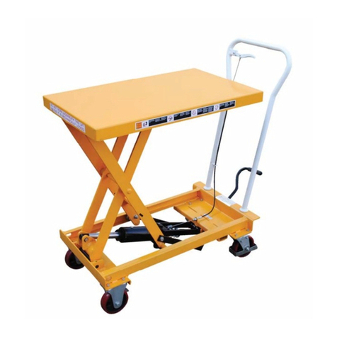
Vestil
Vestil CART-550-AS instruction manual
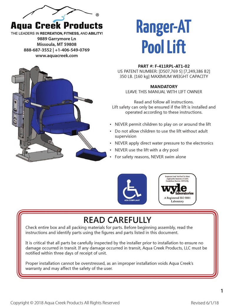
Aqua Creek Products
Aqua Creek Products F-411RPL-AT1-02 manual
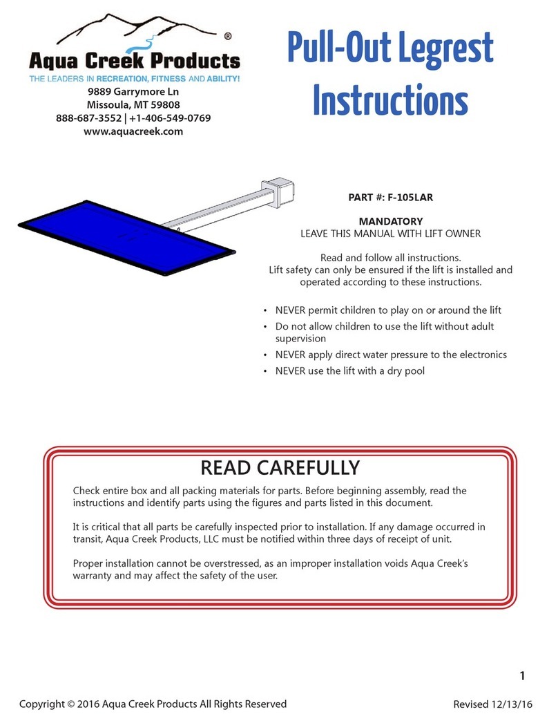
Aqua Creek
Aqua Creek F-105LAR instructions
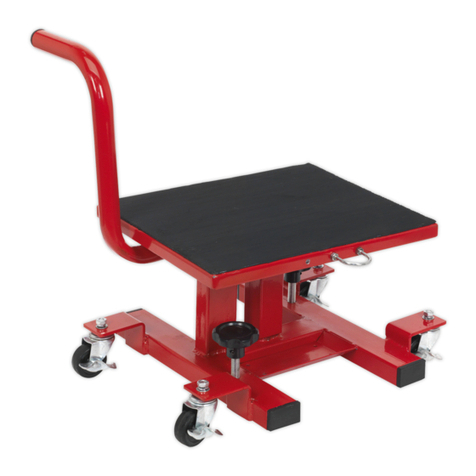
Sealey
Sealey MPSD1 instructions
MoJack
MoJack WorkBench Instructions for assembly and operation

R. Beck Maschinenbau
R. Beck Maschinenbau HS 2000 FH operating manual

Titan Lifts
Titan Lifts Master Series Installation, operation & maintenance manual
Enerpac
Enerpac MLSF3 Operation and maintenance manual

ATH-Heinl
ATH-Heinl Pure Lift 2.40 user manual
Vitea Care
Vitea Care DAVID user manual
Sealey
Sealey MC402.V4 instructions
