Forza 4ZA Cirrus Pro Fast Aero User manual

4za cirrus tt handlebar | manual | 1
cirrus pro fast aero handlebar
4ZA owners manual
TYPE: 7DE
LAST UPDATE: 19/11/2014

4za cirrus tt handlebar | manual | 2
INDEX
0. UPDATES.............................................................................................................................. 3
1. WARNINGS........................................................................................................................... 3
2. TECHNICAL INFORMATION................................................................................................... 3
2.1. COMPATIBILITY .......................................................................................................... 3
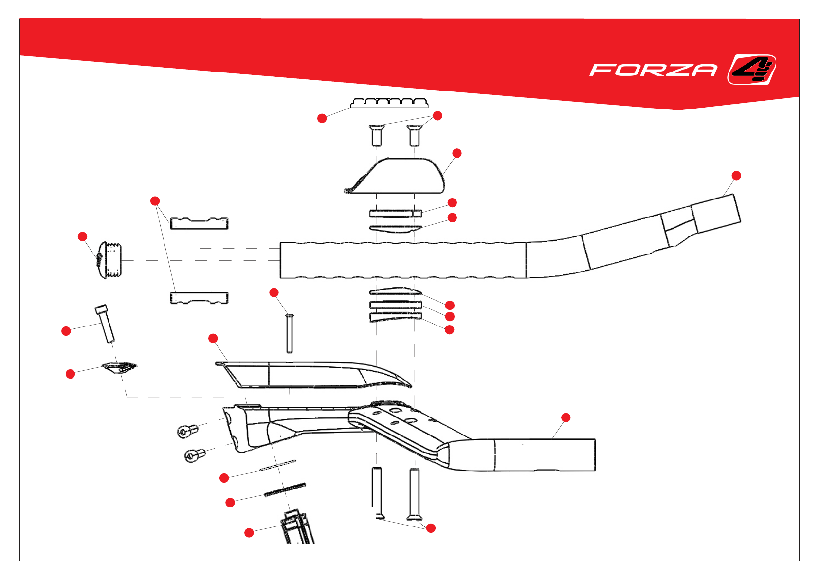
3. PARTS AND TOOLS ...............................................................................................................4
3.1. PARTS .........................................................................................................................4
3.2. TOOLS ........................................................................................................................ 7
3.3. TECHNICAL INFORMATION ......................................................................................... 7
4. TORQUE SETTINGS............................................................................................................... 8
5. SETUP AND INSTALLATION................................................................................................... 8
5.1. HANDLEBAR ASSEMBLY STEPS .................................................................................... 9
5.1.1. EXTENSION INSTALLATION STEPS.......................................................................9
5.1.1. ARM REST INSTALLATION STEPS ........................................................................10
5.2. EXTENSION SETTINGS................................................................................................ 11
5.2.1. EXTENSION WIDTH............................................................................................ 11
5.2.2. EXTENSION HEIGHT ..........................................................................................12
5.2.3. EXTENSION ANGLE........................................................................................... 14
5.2.4. EXTENSION LENGTH .........................................................................................16
5.3. ARMREST SETTINGS ...................................................................................................17
5.3.1 ARMREST HEIGHT AND LENGTH..........................................................................17
5.3.1 ARMREST WIDTH AND ANGLE.............................................................................17
5.4. CABLE ROUTING BRAKE CONTROLS ...........................................................................18
5.5. CABLE ROUTING ELECTRONIC SHIFT CONTROLS ........................................................19
6. EXPANSION SETS.................................................................................................................21
6.1. RISER SET...................................................................................................................21
6.2. 50° EXTENSIONS ....................................................................................................... 22
7. MAINTENANCE................................................................................................................... 23
8. PRODUCT REGISTRATION................................................................................................... 23
9. INFORMATION ................................................................................................................... 23
8.1. WARRANTY ............................................................................................................... 23
8.2. MANUAL MODIFICATIONS ........................................................................................ 23

4za cirrus tt handlebar | manual | 3
0. UPDATES
The development of frames, forks and components is a continuous running process. Therefore we strongly advise to check our website for new updates before reading this
information sheet.
1. WARNINGS
!WARNING!
Bicycle riding can be, and often is, extremely dangerous. Your 4ZA Aerobar system was designed and manufactured using state of the art technology and materials.
It meets and exceeds the applicable EN-standard. Nevertheless, the poor condition of many of our roads, your speed on impact, dangerous climatic conditions, your weight and
your dexterity as a rider are just a few of factors which contribute to possible and even foreseeable impact energies well beyound your 4ZA handlebar’s capabilities.
No handlebar, including your 4ZA handlebar & extensions, can withstand ALL such foreseeable impacts.
!WARNING!
Aerobars can require riding positions that are new or different to many riders.it is advisable to practice using the 4ZA Aerobar system in a low trafc area to become
accustomed to any changes in the steering or handling characteristics of the bike. please exercise extreme caution when using these types of handlebars for the rst time.
Also make sure that you continue to look forward when driving and do not look towards the ground.
2. TECHNICAL INFORMATION
2.1. COMPATIBILITY
!IMPORTANT!
The 4ZA Aero basebar with integrated stem is designed EXCLUSIVELY for use with forks featuring a carbon ber steerer tube with 28.6 mm steerer tube clamp diameter.
Read the instructions of the manufacturer of any aditional items (brake levers, shiftersn clip-on’s etc.) carefully.

4za cirrus tt handlebar | manual | 4
3. PARTS AND TOOLS
3.1. PARTS
NO.* Part part code weight/pc (gram) quantity
1 basebar HBMTTT4ZA001 270.0 1
2 extension bar set 15° HBPTTT4ZA002 136.0 1
3 end cap with hole set HBPTTT4ZA006 2.3 1
4 armrest set HBPTTT4ZA003 33.0 1
5 armrest pad set HBPTTT4ZA004 62.0 1
6 (page 13) bridge HBPTTT4ZA019 21.1 1
7 expander FPLCRN4ZA004 54.6 1
8 Top cover HBPTTT4za001 30.0 1
9 top cover bolt hbpttt4za033 1.4 1
10 rubber ring HSprubfsa004 0.4 1
11 sealing ring hsprubfsa003 0.7 1
12 extension insert spacer HBPTTT4za007 6.0 4
13 (page 14) 5° extension insert spacer hbpttt4za015 7.1 2
14 extension spacer hbpttt4za008 1.8 4
15 (page 14) 5° extension spacer hbpttt4za016 3.0 2
16 basebar spacer left hbpttt4za009 2.6 1
16 basebar spacer right hbpttt4za010 2.6 1
17 (page 13) spacer 3 mm hbpttt4za022 2.0 2
18 spacer 5 mm hbpttt4za011 3.8 4
19 (page 13) spacer 10 mm hbpttt4za012 7.6 4
20 M6 bolt 15-50 mm (step size 5 mm) bltnobnob0(22 to 29) 3 to 9.5 4
21 (page 6) stickerset stittt4za002 0.9 1

4za cirrus tt handlebar | manual | 5
20
20
12
9
8
1
2
4
10
8
18
14
16
3
10
11
5
7
7
7

4za cirrus tt handlebar | manual | 6
Graphics and colors of the sticker set depend on the graphics of the Cirrus Pro TT kit.
21

4za cirrus tt handlebar | manual | 7
Component Spec value
Basebar width (center - center) 400 mm
basebar Narrow extension spacing 100 mm
basebar wide extension spacing 180 mm
extensions shape S-bend
extensions tilt 0° or 5°
bridge width 100 mm
3.2. TOOLS
− 2, 4, 5, 6 mm Hex wrenches
− Torque wrench
− Wheel quick release
− Cable guide
− Friction paste
− Grease or titanium anti-seize for titanium bolts
− Isopropyl alcohol
− 400 grit sandpaper
3.3. TECHNICAL INFORMATION

4za cirrus tt handlebar | manual | 8
4. TORQUE SETTINGS
!IMPORTANT!
Please make sure to regularly inspect bolt torque. You should never exceed the advised torque settings, this can lead to damage, cracks or fatigue of the 4ZA TT kit
resulting into hazardous riding conditions. Likewise you should never ride with your 4ZA TT kit loose.
*No: part indicated on page 5.
5. SETUP AND INSTALLATION
Follow the steps given on page 9 and 10. To ensure the brake and shift controls are mounted correct instantly it is recommended to rst dene the appropriate position of
extensions and armrest pads. Therefore page 11 to 16 explain how to adjust the 4ZA TT handlebar to t your optimal riding position. If the desired position is already known than
please proceed to page 18 to 20 to acquire the necessary information concerning cable routing. However pay attention to all remarks given on page 11 to 16.
To dene the optimal riding position, mount the 4ZA TT kit on the appropriate bike and make adjustments to the cockpit setup using the guidelines given on the following pages.
Make sure to apply the appropriate torque levels on all components before applying any loads.
Use the exploded view on page 5 as a guide to install the 4ZA TT kit.
!WARNING!
Do not ride your bike without functional brakes installed. this can lead to hazardous situations resulting in material damage, wounding or even fatal injuries.
n0.* Component Torque (Nm)
/ Steerer clamp bolts 8
6 top cover bolt 2
12 M6 basebar bolt 4

4za cirrus tt handlebar | manual | 9
5.1. HANDLEBAR ASSEMBLY STEPS
!IMPORTANT!
First assemble the 4ZA Cirrus TT kit without cable routing to determine the desired positions. After determining the desired position disassemble and reassemble the 4ZA TT kit
with cable routing. Consult page 17 to 20 to make sure the cable routing is done appropriately.
5.1.1. EXTENSION INSTALLATION STEPS
The rst step in the 4ZA TT handlebar kit installation is the installation of the extensions. Page 11 to 16 provide the necessary information concerning the adjustability of the
extensions and the necessary components to achieve the desired setup. Pay attention to all warnings given on page 10 to 15. Assembly of the TT kit is considerably easier with two
persons. Use the exploded view on page 5 as a guide. Regardless of the position of the extensions the assembly process uses the following 14 steps:
Step 1: Position the basebar on the bicycle.
Step 2: Determine the desired extension width (Page 11).
Step 3: Determine the desired extension height and derive the appropriate bolt length (page 12 and 13), pic the necessary spacers and bolts.
Step 4: Determine the desired extension angle (Page 14). Pic the appropriate extension spacers and extension insert spacers.
Step 5: determine the desired extension length (Page 16).
Step 6: Route the brake controls through the basebar (Page 18), rst assemble the TT kit without cable routing).
Step 7: Route the shift controls through all components needed to install the extensions (Page 19 and 20), pay close atention not to forget to route the cables through the
extension insert spacer. Pay attention to the mounting direction and to the mounting order of the spacers. (rst assemble the TT kit without cable routing).
Step 8: Place one of the in step 3 selected M6 bolts through the predetermined hole in the basebar.
Step 9: Position a basebar spacer on top of the basebar. Use the M6 bolt to hold the spacer in place.
Step 10: Stack the predened amount of spacers on top of the basebar spacer. Use the M6 bolt to keep the stack into position.
Step 11: End the stack with an extension spacer, pay attention to the mounting direction of the 5° extension spacer..
Step 12: Position the extension on top of the stack, make sure to place the M6 bolt through the predened hole in the extension.
Step 13: Place the extension insert spacer inside the extension. Use a wheel quick release to make positioning easier (page 15) Pay attention to the insert position of the 5°
extension insert spacer.
Step 14: Slightly tighten the M6 bolt using a 4 mm allen key, position and tighten the second M6 bolt. Tighten both bolts to the advised torque settings of 4Nm.
repeat this process for both extensions.

4za cirrus tt handlebar | manual | 10
5.1.1. ARMREST INSTALLATION STEPS
The second step in the 4ZA TT handlebar kit installation is the installation of the armrests. Page 17 provides the necessary information concerning the adjustability of the
armrests and the necessary components to achieve the desired setup. Pay attention to all warnings given on page 17. Assembly of the TT kit is considerably easier with two
persons. Use the exploded view on page 5 as a guide. Regardless of the position of the armrests the assembly process uses the following 13 steps:
Step 1: Determine the desired armrest height and derive the appropriate bolt length (page 12 and 13), pic the necessary spacers and bolts.
Step 2: Determine the desired armrest position on the extensions (page 17).
Step 3: Determine the desired armrest width (page 17)
Step 4: Stick a velcro sticker on top of the armrest.
Step 5: Place one of the M6 bolts through the appropriate hole.
Step 6: Flip the armrest upside down and stack the predened amount of spacers on top of the ipped armrest. Use the M6 bolt to keep the stack into position.
Step 7: End the stack with an extension spacer.
Step 8: Flip the subassembly around and place them on the predened position on the extensions.
Step 9: Place the extension insert spacer inside the extension. Use a wheel quick release to make positioning easier (page 15).
Step 10: Slightly tighten the M6 bolt using a 4 mm allen key, position and slightly tighten the second M6 bolt.
Step 11: Adjust the armrest position by moving the bolt slot relative to the M6 bolt.
Step 12: Tighten both bolts to the advised torque settings of 4Nm.
Step 13: Stick the velcro armrest pad to the velcro sticker applied in step 4.
repeat this process for both arm rests.

4za cirrus tt handlebar | manual | 11
5.2. EXTENSION SETTINGS
The position of the extensions can be altered in width, height, angle and length. Mount the extensions so the handholds are located in the desired position. Armrest pads can
subsequently be moved relative to the extensions allowing to optimize pressure points and position.
5.2.1. EXTENSION WIDTH
The basebar offers the possibility to mount the extensions either at a distance of 100mm or of 180mm relative to each other.
!IMPORTANT!
The 180 mm extension width position does not allow for a stack of spacers higher than 20 mm!

4za cirrus tt handlebar | manual | 12
5.2.2. EXTENSION HEIGHT
Height of the extensions can be determined by inserting the appropriate combination of spacers. Start the stack using a basebar spacer, end the stack using an extension spacer.
Stacks higher than 20 mm can be achieved by using the riser set, extra information on this set can be found in the topic expansion sets.
!IMPORTANT!
In case of a stack of spacers higher than 20 mm it is obliged to add a bridge for added stability. This bridge should be inserted just below the extension spacer.For stacks of less
than 20 mm a bridge may be used.
!IMPORTANT!
Pay attention to the mounting direction of all spacers. bulges and dents are integrated in the spacer shape in order to improve stability of the stack.
Pay attention to the different bolt size for each stack height.
extension spacers stack height
(mm)
bolt length (mm)
0 30
3 35
5 35
8 40
10 40
13 45
15 45
18 50
20 50
arm rest spacers stack height
(mm)
bolt length (mm)
0 15
3 20
5 20
8 25
10 25

4za cirrus tt handlebar | manual | 13
10 mm
5 mm
3 mm
3 mm
5 mm
10 mm
19
18
17
17
18
19
6

4za cirrus tt handlebar | manual | 14
5.2.3 EXTENSION ANGLE
The extensions can be mounted at an angle of 0 or +5 degrees. Depending on the angle different extension spacers and extension insert spacers have to be used. The 4ZA TT kit
contains two different types of extension spacers and extension insert spacers. The 5° extension spacer is noticeably thicker than the 0° extension spacer, as shown on the
image below. The 5° extension insert spacer is marked with the letters U and D, in contrast to the 0° spacer which does not contain any marks. The U side of the 5° extension insert
spacer has to be pointed facing the upward side of the extension. The D side of the 5° extension insert spacer has to be pointed facing the downward side of the extension.
0° extension spacers should always be used in combination with 0° extension insert spacers. Equally 5° extension spacers should always be used in combination with 5°
extension insert spacers.
0° Extension spacer 5° Extension spacer
0° Extension insert spacer side 5° Extension insert spacer side
0° Extension insert spacer top 5° Extension insert spacer top
D
U
14
12
12 13
13
15

4za cirrus tt handlebar | manual | 15
Thread a wheel quick release in the bottom of the extension insert spacer to make positioning of the insert inside the extension easier. Remove the
wheel quick release after nishing installation of the extension insert spacer (as indicated in RED on the image below).
!IMPORTANT!
When mounting the extensions at an angle of 5° pay close attention to the insert direction of the extension insert spacers. If the extensions are to be positioned at an angle of +5°
make sure to mount the extension spacer pointing forward and insert the extension insert spacer with the letter U (UP) rst in the extensions.
Wheel quick release
1
12
3 4

4za cirrus tt handlebar | manual | 16
5.2.4. EXTENSION LENGTH
The extensions are provided with a series of holes that cover a 135 mm range of mounting positions with a step size of 15mm. Note that the arm pad xation position is not related
to the extension xation position.
!IMPORTANT!
To prevent the extensions from hitting body or bike parts we advise to cut them to size when mounted in the shortest position (left image below). Use a metal saw and
sandpaper to realise a clean cut.

4za cirrus tt handlebar | manual | 17
5.3. ARMREST SETTINGS
The position of the arm rests can be altered in height, length, width and angle.
5.3.1. ARMREST HEIGHT AND LENGTH
Similar to changing the extension height, the arm pad height can be altered using the appropriate selection of spacers.
5.3.2. ARMREST WIDTH AND ANGLE
the arm pads can be mounted at two different widths relative to the position of the extensions. The slot for the front nut allows the arm pad to rotate around the rear nut resulting
in the possibility to alter the arm pad angle..

4za cirrus tt handlebar | manual | 18
5.4. CABLE ROUTING BRAKE CONTROLS
The 4ZA aero basebar features an internal cable routing system. Depending on the brake setup on your bike you will run the cable full internal (RED) or semi internal (GREEN) as
shown in the schematic representation on page 16. Dotted parts of the cable are run internal.
Use the brake cable inner as a guide. Insert the end of the brake cable inner in the exit hole of the brake cable as indicated by the dots on the schematic representation on page 16.
Take into account the brake setup as mentioned above. manually guide the cable to the tips of the base bar. Slide the brake outer over the inner cable starting at the tips
of the basebar. Cut the outer cable to size and install the brake cable inner.
!IMPORTANT!
Dene the correct setup of the extensions and armrest pads prior to the installation of the electronshift wire.

4za cirrus tt handlebar | manual | 19
5.5. CABLE ROUTING ELECTRONIC SHIFT CONTROLS
The 4ZA aero kit was designed to run the electric cables full internal. For you to route the cables correctly it is required to disassemble the TT extensions. The exploded view below
shows an example cable routing. Check your setup position rst to dene which holes and spacers to route the electronic shift controls cables through. Start cable routing at the
dot indicated on the exploded view.
!IMPORTANT!
Pay attention to the exploded view below while running internal cable routing. Make sure not to forget to thread the cable through the extension insert spacer!
Thread a wheel quick release in the bottom of the extension insert spacer to help positioning of the extension insert spacer. The shimano TT interface can be tted below the top
cover.
extension insert spacer
extension spacer
spacer stack
basebar spacer

4za cirrus tt handlebar | manual | 20
Table of contents
Popular Bicycle Accessories manuals by other brands

KUNTENG
KUNTENG KT-LCD3 Product user manual

Sigma
Sigma EOX VIEW 1300 Operating and mounting instructions

blackburn
blackburn OUTPOST BIKE & CAMP 7108800 quick start guide

CAMPAGNOLO
CAMPAGNOLO BORA ONE 35 user manual

Busch+Müller
Busch+Müller LUMOTEC IQ Eyro 163B instruction manual

BIGSTONE
BIGSTONE C800-TFT instructions