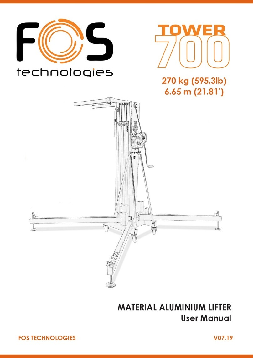
FOS Technologies Tower 400 User manual

FOS TECHNOLOGIES V07.19
MATERIAL TELESCOPIC LIFTER
User Manual
125 kg (275.6lb)
3.8 m (12.5’)

2
FOS 400
F1302K
F1301K
F1303K
F4001K
F1201K
F2102K
F2103K
F1001K
F7001K
Screw
Nut
F2104K
Strap cap
Section 1
Section 2
Section 3
A
B
C
Leg
Strap
Leg cap
Winch

3
FOS 400
F1007K
F1007K
F1007K F8002K
F8002K
F8002K F1102K
F2002K
F1008K
F1103K
F2110K
F2182K
A.1
F1012K
F1006K
A.1
F8003K
F7002K
A.1
Lock
Screw
Screw
Bracket
A

4
FOS 400
F2105K
F2109K
F2107K
F2101K
F1002NK
F7001K
Tornillo / Screw
Tuerca / Nut
F2106K
F1004NK
F3001K
F2001K
F1010K
F1101K
F1004NK
F1004NK
Soporte jo tirantes /
Fixed strap support
Tapón superior pata/
Leg upper cap
Pomo soporte patas /
Leg support knob
Soporte patas /
Leg support
Gatillo / Lock
F7001K
Tuerca / Nut
F1001K
Tornillo / Screw
C
B
C.1 - Lower pulleys set Section 2 (Ref.1302)

5
FOS 400
F9001K
F2111K
F4001K
F1003K
F8001K
Screw
Washer
F7001K Nut
F1009K
F2003K
F7002K F8004K
F8003K
F9001K
D.1
D
F2131K
F1006K
Screw
Extension bar
Cable clamp
Steel cable
Cable
Winch
D.1

6
FOS 400
Code/Código Description/Descripción
F1001K M8x55 hexagonal screw
F1002NK M8x25 hexagonal screw
F1003K Allen screw M8x16
F1004NK Conic allen screw M5x12
F1006K Allen screw M10x25
F1007K Allen screw M6x20
F1008K Special M10 screw
F1009K Hexagonal screw M10x40
F1010K Conic screw M4x35
F1012K Allen screw M6x10
F1101K 10mm axis plate
F1102K Pletina portapolea
F1103K FOS 400 threaded pulley cover plate
F1201K FOS 400 Leg
F1301K Section 3 FOS 400
F1302K Section 2 FOS 400
F1303K Section 1 (Base) FOS 400
F2001K Pulley Ø 50
F2002K Pulley Ø 40 (Upper pulley support FOS-400)
F2003K Pulley Ø 40 (Cable entry)
F2101K Upper leg tap
F2102K Ground leg tap
F2103K Leg strap
F2104K Strap tap
F2105K Sliding leg support
F2106K Fixed strap support
F2107K Short lock for sliding leg bracket
F2109K Knob for sliding leg bracket
F2110K 35x35 mm Bracket
F2111K Cable clamp screw Ø4 mm
F2131K FOS 400 extension bar
F2182K FOS 400 Lock
F3001K 10x50 steel axis
F4001K 450 kg winch
F7001K Auto-block nut M8
F7002K Auto-block nut M8
F8001K Flat M8 washer
F8002K M6 washer
F8003K Flat M10 washer
F8004K M12 washer
F9001K Cable FOS 400 (Ø4mm)
LISTA DE REPUESTOS / SPARE PARTS LIST

7
FOS 400
Operating Instructions
1 - INTRODUCTION.
Dear user. Thank you purchasing your FOS 400 lifter. We hope you will be very satised
with it.
This manual has been written so that you can understand how to effectively use the lift
and most importantly, so that you can use it safely.
It is important that you fully read the manual and follow the instructions carefully before
using your lift. All FOS lifts undergo a very strict quality control process during their
manufacture. So that your lift always works properly please only purchase original FOS
parts from an authorized distributor or dealer. The user waives all warranty rights if using
parts other than FOS or if the product is manipulated in any way by an unauthorized third
party. When requesting parts, please refer to the diagrams in the back of this manual and
quote the serial number and year of manufacture located on your lifter.
2.- TECHNICAL SPECIFICATIONS.
The FOS 400 lifter has been designed for vertically lifting lighting, trussing and other
materials in the professional light and sound sector.There is various supports or acces-
sories available, please refer to our website or catalogue.
2.1 - Max. load: 125 kg (275.6 lb).
2.2 - Min. load: 25 kg (55 lb).
2.3 - Max. height: 3.2 m (10,5’) (with extension bar 3.8m (12,5’)
2.4 - Folded. height: 1.26 m (4,1’)
2.5 - Transport surface: 1,27x0.27x0.36m (4.17’x0.89’x1.18’).
2.6 - Shipping dimension: 1,28x0.29x0.18m (4.20’x0.95’x0.59’). (Handle removed)
2.7 - Work surface: 1.50 x 1.50 m (4,90’ x 4,90’)
2.8 - Weight: 21 kg (46 lb)
2.9- Winch: 450 kg certied.
2.10 - Cable: Steel DIN 3060. Tensile strength 180 kg/mm2. Anti-torsion & anti-corrosion
4 mm cable diameter.
2.11 - Construction material: Steel proles EN 10305.
2.12 - Three-prole telescopic system operated by steel cable driven by pulleys with
metal protected bearing pads. Adaptor Ø35 mm.
2.13 - Antirust protection priming paint bathed black steel, covered with cured polyester
dust.

8
FOS 400
Operating Instructions
3 - SAFETY GUIDELINE.
3.1.- Situate the tower on a solid and at surface.
3.2.- Check that the support system is xed by the security trigger and that the tower is
in a upright position.
3.3.- Check that the tower is locked in its working position with the safety lock.
3.4.- When used outdoors, place the tower on a hard surface and if necessary secure it
against excess wind force via cable braces.
3.5.- Do not use ladders nor lean them against the lifter.
3.6.- Be careful with any cables, prominent objects etc. placed above the tower.
3.7.- Do not stand underneath the load.
3.8.- Do not move the tower when it is elevated or loaded.
3.9.- Before using the tower, check the condition of the cable. This must be free of cuts
and frays. Never use damaged cables.
3.10.- Never dismount the winch handle or any element of the winch under any circum-
stance.
3.11.- Once the tower is set-up in its working position we recommended the winch handle
is locked to avoid anyone interfering with it.
3.12.- The minimum load for a safe operation of the brake is 25 kg. The brake will not
function without this minimum load.
3.13.- Do not grease or lubricate the brake mechanism of the winch.
3.14.- This lift cannot lift human beings.
3.15.- For transportation it is necessary to retract all proles and lock them with the co-
rresponding safety lock.
4.- OPERATION.
4.1.- Place the tower on a at and solid surface where it is going to be used.
4.2.- Unlock the safety lock from the legs support system. Slide the support system
downwards until the lock has reached the required position.
4.3.- Attach the load to the tower using the desired support (the support varies upon the
application), and ensure it is only used to lift loads vertically. The minimum load is 25 kg.
4.4.- Elevation: Extend the tower by turning the winch handle clockwise, lifting the load
to the desired height.

9
FOS 400
Operating Instructions
4.5.- Hold: Release the winch handle, it will remain in position by the action of the
winch’s automatic brake. Ensure the FOS lock has introduced in to the prole by turning
the handle slightly anti-clockwise.
4.6.- Continue elevating: Turn the winch handle again clockwise and lift the load until
the second prole is fully extended. Release the handle which will remain xed by the
winch’s automatic brake and proceed to ensure that the FOS lock has introduced into the
second prole by turning the handle again anti-clockwise. The tower can be stopped in
any desired intermediate position. Simply release the winch handle and secure the tower
by inserting the corresponding FOS lock into the hole which is closest to the required
position.
4.7.- Descent: Descending the load follows the same procedure but in reverse. Firstly
unlock the FOS lock and turn the winch handle anti-clockwise, until the rst prole is
completely folded down. Now unlock the next FOS lock and retract the second prole.
Just as when lifting the load, the lift may be stopped at any intermediate position.
4.8.- Transport: When transporting / carrying the lift it is necessary to fold the tower by
retracting all the proles completely. Then close the sliding support piece and x it with
the safety lock and tightening the knob.
5.- MAINTENANCE.
5.1.- All cables must be checked regularly. Faulty cables must be replaced immediately.
Do not use the lifter with faulty cables as it is potentially very dangerous. Only use DIN
3060 cables, supplied from an authorised dealer.
5.2.- The lifter is delivered ex factory completely greased. Depending on its mechanical
use though, we recommend that the crown wheel of the winch, the pads & bushings of
the drive shaft, the handle thread and the proles of the lift are periodically greased.
ATTENTION:
Do not apply oil or grease to the brake mechanism.
The brake discs have been pre-greased with a special heat and pressure resistant grea-
se. To avoid malfunction to the winch brake, no other products must be used except the
original provided by the company. It is not necessary to grease the brake discs.

10
FOS 400
Operating Instructions
5.3.- Your lifter should be inspected at least once a year by a specialized / authorized
service centre.
5.4.- Only original FOS spare parts must be used to guarantee the reliability and opera-
tional safety of your lifter. The user shall lose all warranty claims if he uses anything other
than original spare parts or modies this product in any way.
5.5.- In case a spare part is required please indicate the reference number which can be
found in the spare parts list at the back of this manual.
6.- WARRANTY.
All FOS TECHNOLOGIES lifts come with 2 years warranty. This warranty period is from
the date of purchase. FOS will repair any defect product caused by either faulty materials
or poor workmanship free of charge within this period as long as the parts are tted by
an authorized dealer.
If the product have been manipulated in any way or a repair attempted by an unauthori-
zed dealer the warranty will be invalid. This warranty does not cover damage occurred
by improper use.
7.- CERTIFICATIONS.
FOS reserves the right to make any modication/alteration to the lift without prior notice.
Any modication/alteration would be an innovation, intended to improve the product.


FOS Technologies LTD
Bulevard Iliensko Shose 8
Sladova Baza ZMM, Soa, BG
www.fos-lighting.eu
Call Center : +30 2102811700
Table of contents
Other FOS Technologies Lifting System manuals
Popular Lifting System manuals by other brands

smv
smv MULTI-LIFT SYSTEM instruction manual

Clarke
Clarke Strong-Arm CPL30S Operating & maintenance instructions
Rotary
Rotary SGL35 Operating and maintenance manual

LGMG
LGMG A45JE Service manual

Custom Equipment
Custom Equipment HB-P830 Maintenance and troubleshooting manual
Nußbaum Hebetechnik
Nußbaum Hebetechnik 2.30 SL E Operating Instruction and Documentation
AL-KO
AL-KO B 400-2,0 Original instructions for use
AMGO
AMGO Hydraulics PRO-12ASX Installation and service manual
Liko
Liko Likorall 242 S Instruction guide
rav
rav KPH-40ECGA Operation and maintenance manual

Lippert
Lippert Titan Leveling Systems installation manual
AMGO Hydraulics
AMGO Hydraulics MR06 Installation and service manual
