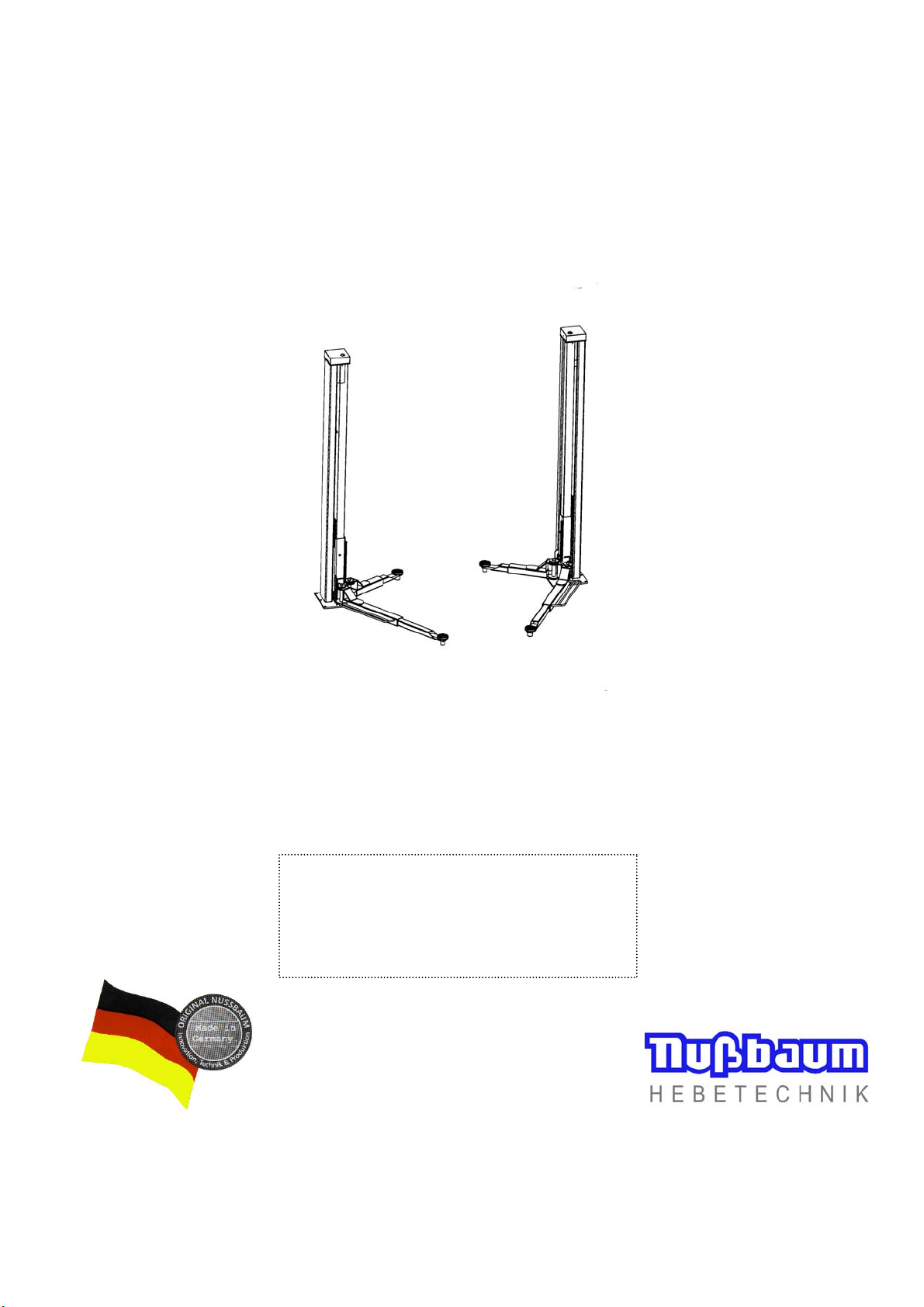
Operating Instruction and Documentation
2.30 SL E
- 2 -
Table of contents
Foreword................................................................................................................................................ 3
1. Introduction............................................................................................................................................. 5
2. Master document of the lift..................................................................................................................... 6
2.1 Manufacturer ................................................................................................................................... 6
2.2 Application....................................................................................................................................... 6
2.3 Changes of construction................................................................................................................... 6
2.4 Changing of the installation place ................................................................................................... 6
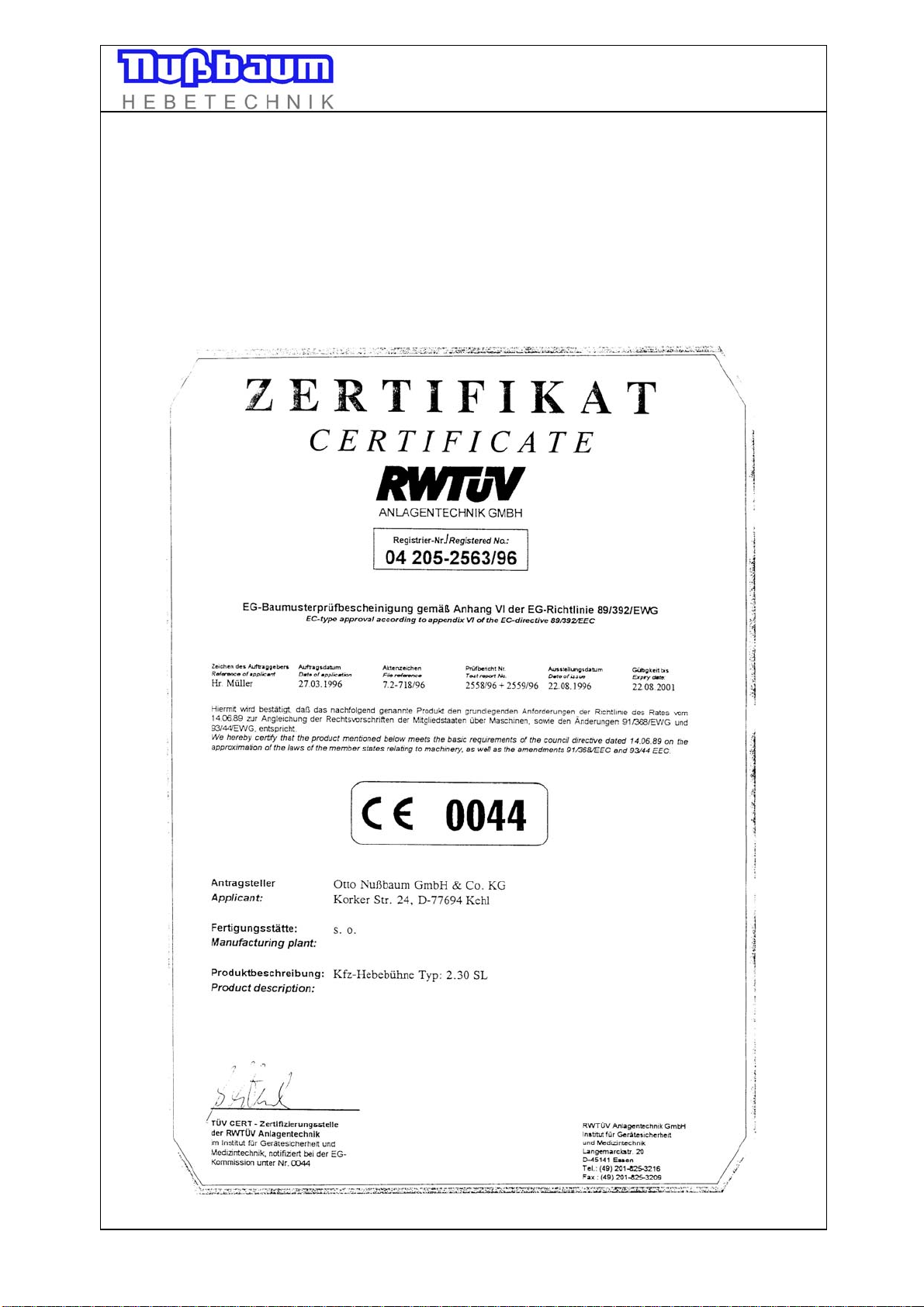
2.5 CE-certificate/attestation of conformity.......................................................................................... 7
3. Technical Information............................................................................................................................. 8
3.1 Technical ratings.............................................................................................................................. 8
3.2 Safety devices.................................................................................................................................. 8
4. Safety regulations.................................................................................................................................... 9
5. Operating instructions.............................................................................................................................. 10
5.1 Positioning the vehicle..................................................................................................................... 10
5.2 Synchronism of the automotive lift.................................................................................................. 10
5.3 Lifting the vehicle............................................................................................................................ 11
5.4 Lowering the vehicle........................................................................................................................ 11
5.5 LED display visibly at the operating unit......................................................................................... 12
6. Maintenance............................................................................................................................................ 14
6.1 Maintenance schedule of the automotive lift................................................................................... 14
6.2 Adjust of the polyflex-belt............................................................................................................... 15
6.3 Check the carrying nut system......................................................................................................... 16
6.4 Check of the stability of the automotive lift.................................................................................... 16
7. Troubleshooting....................................................................................................................................... 17
7.1 Emergency lowering in case of power failure.................................................................................. 18
7.2 Driving onto an obstacle.................................................................................................................. 18
7.3 Function of safety device................................................................................................................. 18
7.4 Manually equalisation of the lifting carriage................................................................................... 19
7.5 Adjusting of the “Limit switch“...................................................................................................... 19
8. Installation and Initiation......................................................................................................................... 20
8.1 Installation of the automotive lift..................................................................................................... 20
8.1.1 Erection and doweling of the lift............................................................................................. 20
8.1.2 Electro mounting and current connection................................................................................ 22
A) with using ascending pipe and traverse................................................................................. 22
B) without using ascending pipe and traverse............................................................................ 23
8.1.3 Installation the carrying arms........................................................................................................ 23
8.2 Initiation........................................................................................................................................... 24
8.3 Changing the installation place........................................................................................................ 24
9. Security check.......................................................................................................................................... 24
Appendix
Datasheet..................................................................................................................................................... 26
Foundation plan (version with traverse and ascending pipe)...................................................................... 28
Foundation plan (version without traverse and ascending)......................................................................... 29
Block foundation plan (with ascending pipe and traverse)......................................................................... 30
Selection of dowels (with floor covering)................................................................................................... 31
Selection of dowels (without floor covering).............................................................................................. 32
Electrical diagram drawing Part 1............................................................................................................... 33
Electrical diagram drawing Part 2............................................................................................................... 34
Record of installation................................................................................................................................... 35
Record of handing over............................................................................................................................... 36
Document "First security check before Installation"................................................................................... 37
Document "Regular security check"........................................................................................................... 38
Document "Extraordinary security check".................................................................................................. 45