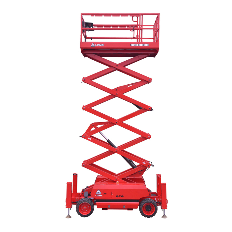
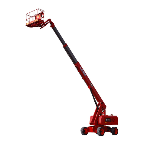
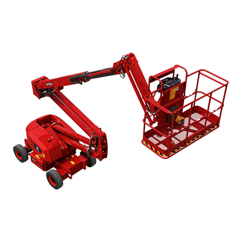
LGMG A45JE User manual

△! WARNING
Before operation and maintenance, the drivers and
maintenance personnel are required to read this manual
thoroughly. Otherwise, fatal accident may occur. This
manual shall be kept properly for future reference by the
personnel concerned.
Service Manual
A14JE
Articulated Boom Mobile
Elevating Work Platform
LINGONG HEAVY MACHINERY CO.,LTD.

Articulated Boom Mobile Elevating Work Platform
Service Manual
880*1230 mm Sextodecimo 8 sheets
First edition, Oct. 2022 First print, Oct. 2022
L I N G O N G H E AV Y M A C H I N E R Y C O . , LT D .
Add.: 12F, Building 3, Lushang Olympic City, No. 9777, Jingshi Road, Lixia District, Jinan
City, Shandong Province, China
Tel: 86-0531-67605017 Technical service: 86-4009666569
Web: www.LGMG.com.cn Sales of accessories: 86-0531-67605016

Service manual of Articulated Boom Mobile Elevating Work Platform
I
Contents
Foreword....................................................................................................................................................V
Safety Notices...........................................................................................................................................VI
Safety and Environment............................................................................................................ 1
1.1 Terms and definitions.................................................................................................................... 3
1.2 Before maintenance...................................................................................................................... 3
1.3 Workplace requirements............................................................................................................... 3
1.4 Maintenance and repair safety specification................................................................................ 4
1.5 Intended purpose.......................................................................................................................... 5
1.6 Compliance................................................................................................................................... 5
1.7 Description.................................................................................................................................... 5
Product introduction.................................................................................................................. 7
2.1 A45JE(A1408JDTAE30)Machine parameters ......................................................................... 9
2.2 Lift platform torque specification................................................................................................. 10
2.3 Key component moment table.................................................................................................... 13
Service................................................................................................................................... 15
3.1 Platform assembly...................................................................................................................... 17
Assembling the file box..................................................................................................... 17
Assembling the platform tool box..................................................................................... 17
Assembling the foot switch............................................................................................... 17
Assembling the lifting cross bar........................................................................................ 17
Assembling the protective mount..................................................................................... 17
Assembling the arc shield................................................................................................. 18
Assembling the platform assembly................................................................................... 18
Assembling the load cell................................................................................................... 19
Assembling the stop block................................................................................................ 19
Assembling the swing motor mounting bracket.............................................................. 19
Assembling the platform control unit (PCU)................................................................... 19
Assembling the anti-collision rubber pad ....................................................................... 20
Assembling the platform................................................................................................. 20
3.2 Axle assembly............................................................................................................................. 20
Removing the front axle assembly................................................................................... 20
Removing the rear axle assembly.................................................................................... 21
Removing the wheels....................................................................................................... 21
Assembling the wheels..................................................................................................... 21
Removing the motor......................................................................................................... 22
Removing the reducer assembly...................................................................................... 22
3.3 Jib assembly............................................................................................................................... 22
Removing the swing cylinder............................................................................................ 22

Service manual of Articulated Boom Mobile Elevating Work Platform
II
Removing the jib assembly............................................................................................... 23
Removing the fly jib cylinder............................................................................................. 23
Assembling the swing cylinder, the fly jib cylinder and the jib ......................................... 24
3.4 Cable carrier assembly............................................................................................................... 27
Removing the cable carrier............................................................................................... 27
Assembling the cable carrier............................................................................................ 28
3.5 Boom assembly .......................................................................................................................... 29
Removing the boom assembly......................................................................................... 29
Assembling the boom assembly....................................................................................... 30
Subassembling the boom assembly................................................................................. 31
3.6 Hydraulic tank............................................................................................................................. 33
Assembling the hydraulic tank.......................................................................................... 33
3.6.1 Removing the hydraulic tank............................................................................................ 34
3.7 Cylinder assembly....................................................................................................................... 35
Removing the boom luffing cylinder................................................................................. 35
Assembling the boom luffing cylinder............................................................................... 36
Removing the boom telescopic cylinder........................................................................... 37
Removing the lower leveling cylinder............................................................................... 38
Assembling the lower leveling cylinder............................................................................. 39
Removing the leveling cylinder......................................................................................... 39
3.8 Articulated boom assembly......................................................................................................... 41
Removing the articulated boom assembly....................................................................... 42
Assembling the articulated boom assembly..................................................................... 44
Removing the articulated boom lift cylinder ..................................................................... 45
Assembling the articulated boom lift cylinder................................................................... 46
3.9 Rotary table swing assembly...................................................................................................... 47
Removing the slewing drive assembly............................................................................. 47
Assembling the slewing drive assembly........................................................................... 48
Lowering the rotary table.................................................................................................. 48
3.10 Other components.................................................................................................................... 48
Assembling the battery................................................................................................... 48
Assembling the horn....................................................................................................... 49
Assembling the ground control unit (GCU) assembly.................................................... 49
3.11 Valve group ............................................................................................................................... 50
Installing the spool.......................................................................................................... 50
Boom function valve block.............................................................................................. 50
3.12 Bleeding cylinder....................................................................................................................... 52
Bleeding function pump.................................................................................................. 52
Bleeding slewing motor .................................................................................................. 52
Bleeding driving motor.................................................................................................... 52

Service manual of Articulated Boom Mobile Elevating Work Platform
III
Bleeding steering cylinder .............................................................................................. 52
Bleeding folding jib luffing cylinder................................................................................. 52
Bleeding main boom luffing cylinder and lower leveling cylinder................................... 53
Bleeding main boom telescopic cylinder........................................................................ 53
Bleeding fly jib luffing cylinder and upper leveling cylinder............................................ 53
Bleeding platform swing cylinder.................................................................................... 53
Maintenance.......................................................................................................................... 55
4.1 Compliance and Obedience....................................................................................................... 57
4.2 Checking the Safety Manual....................................................................................................... 57
4.3 Check the Labels and Signs....................................................................................................... 57
4.4 Check for Damaged, Loose or Missing Parts............................................................................. 57
4.5 Check the Hydraulic Oil Level and Leakage .............................................................................. 58
4.6 Check the Pivoting Support........................................................................................................ 58
4.7 Checking the Battery .................................................................................................................. 59
4.8 Check the Wires.......................................................................................................................... 60
4.9 Check the Electrical Contactors ................................................................................................. 60
4.10 Check the Tires and Wheels..................................................................................................... 61
4.11 Check the Drive Hub Oil Level.................................................................................................. 61
4.12 Check for Exhaust Cover of Hydraulic Oil Tank ....................................................................... 61
4.13 Visual Inspection of the Hydraulic Oil....................................................................................... 62
4.14 Platform weighing structure lubrication .................................................................................... 62
4.15 Checking the hydraulic filter ..................................................................................................... 62
4.16 Replace the Reducer Gear Oil ................................................................................................. 63
4.17 Replace theAir Cleaner............................................................................................................ 63
4.18 Replace the Hydraulic Oil and Filter......................................................................................... 63
4.19 Regular maintenance................................................................................................................ 64
4.20 Fault code of Li-battery............................................................................................................. 65
4.21 Routine Inspection and Maintenance Intervals........................................................................ 68
Commissioning....................................................................................................................... 71
5.1 Safety instructions....................................................................................................................... 73
5.2 Machine inspection..................................................................................................................... 74
5.3 Basic test..................................................................................................................................... 75
Start test............................................................................................................................ 75
Emergency stop switch..................................................................................................... 75
Horn switch....................................................................................................................... 75
Basic operation test of ground control unit....................................................................... 75
Basic operation test of platform control unit..................................................................... 77
Hydraulic oil level test....................................................................................................... 79
Travel speed (high speed) test......................................................................................... 80
Braking distance test ........................................................................................................ 80

Service manual of Articulated Boom Mobile Elevating Work Platform
IV
Drive speed limit test........................................................................................................ 80
Braking distance test (at slow speed)............................................................................. 81
Drive enable system test................................................................................................ 81
Gradeability test(30%)............................................................................................... 81
Operation time test......................................................................................................... 82
Lifting height test............................................................................................................. 83
Load test (1.1 times)....................................................................................................... 83
Load test (1.25 times)..................................................................................................... 83
Rated load calibration..................................................................................................... 83
Boom pressure test......................................................................................................... 84
Articulated boom pressure test....................................................................................... 84
Slewing pressure test ..................................................................................................... 85
Steering pressure test .................................................................................................... 85
Appendix................................................................................................................................ 87
6.1 System fault code ....................................................................................................................... 89
6.2 Diagram of common hydraulic part symbols.............................................................................. 90
6.3 Diagram of common electrical part symbols ............................................................................ 100
6.4 Wire harness number description............................................................................................. 105
Main harness..................................................................................................................105
Platform wire................................................................................................................... 106
6.5 Schematic diagram................................................................................................................... 108
Electrical schematic diagram..........................................................................................108
Hydraulic schematic diagram .........................................................................................109

Service manual of Articulated Boom Mobile Elevating Work Platform
V
Foreword
You are welcome to purchase and use the products produced byLingong HeavyMachinery Co., Ltd. This
manual introduces the technical parameters and maintenance adjustment data of Articulated Boom
elevating work platform, and explains the troubleshooting and maintenance process for reference by
qualified professional maintenance professionals. The information contained in this manual are correct
at the time of publication, but due to the continuous improvement of the structure and performance of our
products, the design as well as operation and maintenance instructions of the product may be subject to
change without notice. Forthe latest information about the machine and any questions about thismanual,
please consult our company. In additions, readers of this manual are encouraged to feedback the errors
and put forward suggestions to Lingong Heavy Machinery Co., Ltd., which will be carefully considered in
the future publication and printing of this manual.
This manual is the property of Lingong Heavy Machinery Co., Ltd., and is not allowed to be duplicated or
reprinted without our written permission.
△
!WARNING
Only the personnel who have professionally trained and qualified are allowed to
operate and maintain the machine.
Incorrect operation, maintenance and repair are dangerous and can lead to
personal injury or death.
Before operating or maintaining the machine, the operator should read this manual
carefully. Do not operate, maintain or repair the platform without reading and
understanding this manual.
Please load the machine in strict accordance with the rating, otherwise all the
consequences arising from overloading or unauthorized modification will be borne
by the user.
The operation instructions and precautions in this manual apply onlyto the intended
use of the machine. If the machine is used for an operation that is out of the
specification herein but not prohibited, always make sure that this operation will not
cause personal injury to yourself or others.

Service manual of Articulated Boom Mobile Elevating Work Platform
VI
Safety Notices
The operator shall understand and abide by the current national and local safety regulations. If such
regulations are not available, the safety instructions in this manual shall prevail.
Most of the accidents are caused by failure to comply with the regulations on the operation and
maintenance of the machine. In order to avoid accidents, please read, understand and observe all
warning requirements and precautions in this manual and on the machine before operation and
maintenance. Failure to comply with the instructions and safety rules in this manual and the
corresponding manual on the machine may result in serious injury or even death.
Considering the fact that not all possible hazards are foreseeable, it is impossible for safety notices
in this manual and on the machine to cover all safety precautions. If it is necessary to take steps and
operations not recommended herein, always protect the safety of yourself and others, and keep the
machine from any damage. If the safety of some operations remains uncertain, please consult us or
dealers.
Not only basic mechanical, hydraulic and electrical skills are required to perform most operations.
Specialized skills, tools, lifting equipment and suitable workshops are also required for
some maintenance processes. Considering this, it is strongly recommended for you to get the machine
maintained and repaired in the service center authorized by LINGONG HEAVY MACHINERY CO.,LTD.
The operation and maintenance precautions referred to herein apply only to the intended use of this
machine. If the machine is to be used forother purposes than those listed herein, it is the user oroperator
instead of us that shall take the safety liabilities therefrom. In no case shall any operations expressively
prohibited herein be performed.
For the purpose of this manual, the following signal words are applied to identify safety instructions:
△
!DANGER - Indicating any existing dangers that, if not avoided, will cause serious
injury or even death. This term is also used for the danger that, if not avoided, may
cause serious damage to the machine.
△
!WARNING - Indicating any potential dangers that, if not avoided, may cause
serious injury or even death. This term is also used for the danger that, if not avoided,
may cause serious damage to the machine.
△
!CAUTION - Indicating situations that, if not avoided, may cause minor or
moderate injury. This term is also used for the danger that, if not avoided, may cause
damage to the machine or shorten the life of the machine.

Service manual of Articulated Boom Mobile Elevating Work Platform
1
Safety and Environment

Service manual of Articulated Boom Mobile Elevating Work Platform
2

Service manual of Articulated Boom Mobile Elevating Work Platform
3
1.1 Terms and definitions
Administrator:
The entity or individual that directly controls the use and application of the lifting platform, which
usually refers to the owner, the renter or the authorized personnel of owner who obtains the control right
of the lifting platform;
Operator:
Personnel who has been professionally trained and mastered qualified knowledge and practical
experience to operate the lifting platform.
Qualified personnel:
Personnel who has recognized academic qualifications, certificates, professional status or relevant
professional knowledge, has been professionally trained and experienced.
Safety announcement:
Relevant safety information issued by Lingong Heavy Machinery Co., Ltd.
1.2 Before maintenance
1. Read and follow the safety rules and maintenance instructions in the corresponding operation
manuals on the machine.
2. Ensure that all necessary tools and parts are in place.
3. Do not use parts not sold by Lingong Heavy Machinery Co., Ltd.
4. Please read each step thoroughly and follow the instructions, and do not try to perform repair by
shortcut, as this is dangerous.
1.3 Workplace requirements
The machine shall be able to work under the following safety conditions:
1. The environment humidity shall be less than 90%(+25 ℃).
2. The machine shall be able to work normally under the following safety conditions:
-The ambient temperature shall be -20 ℃~ +40 ℃;
- The wind speed shall not be greater than 12.5 m/s/28mph;
- The vehicle shall never be used in corrosiveness environment with such materials as inflammable
and explosive or acid and alkali.
3. During normal operation or repair, the movement of the mechanism and components and parts may
cause danger to the human body, and protective device shall be set.
4. Measures shall be taken to prevent danger caused by components and parts falling on the platform.
5. When repairing, place a qualified fire extinguisher in a readily available position.
6. Keep the work site clean and tidy to prevent dirt from entering the machine and causing damage to
the components and parts.

Service manual of Articulated Boom Mobile Elevating Work Platform
4
7. Please ensure that the forklift, crane or other lifting or supporting equipment are strong enough to
support and stabilize the weight to be lifted.
8. During repair, please do not reuse disposal fastener (such as cotter pin and self-locking nut), so as
to avoid abnormal functioning due to reuse of such parts.
9. Please dispose of the discarded fluid correctly in an environmentally friendly way.
10. Make sure the work site is well ventilated and well lit.
1.4 Maintenance and repair safety specification
1. The following precautions shall be taken before the adjustment and repair of the machine:
Park the machine on a solid and level ground;
Block the front and rear of the wheel to ensure that the wheel will not rotate or move;
Cut off the power supply and ensure that the machine is in a non-start status;
Set all control devices in the "off" status to avoid unexpected start of operating system;
If possible, lower the platform to the lowest position, otherwise, ensure that it will not fall;
Before loosening or removing the hydraulic component, release the hydraulic oil pressure of the
hydraulic pipeline;
Place the safety support as required.
2. Maintenance personnel training:
Maintenance personnel must be trained by qualified personnel to inspect and maintain the machine
in accordance with the requirements of this manual.
3. Replacement of parts
The parts for replacement shall be genuine parts of our company, otherwise we will refuse tomaintain
or repair the product.
4. Service Bulletin
The machine maintenance and repair by users shall be in strict accordance with the service bulletin
issued by the Lingong Heavy Machinery Co., Ltd.
5. Vehicle welding repair
1) First, shut down the engine and cut off the low-voltage power supply;
2) The worker shall have special operation certificate;
3) Clean up the surrounding flammables and apply for welding permit;

Service manual of Articulated Boom Mobile Elevating Work Platform
5
4) Protect the vehicle body to prevent splashing and fire;
5) Operate in strict accordance with the welding process;
6. Precautions of the battery maintenance
1) Battery run-out is strictly prohibited during storage. It is strictly prohibited to keep the battery in the
run-out status during storage. Please charge the battery immediately after the battery runs out.
2) Correctly control the charging time. In the process of use, accurately control the charging time
according to the actual situation, and control the charging frequency with reference to the usual use
frequency and driving mileage.
3) Prevent exposure to the sun. Environment with too high temperature will increase the internal
pressure and electrolyte loss of the battery, causing battery activity reduction and accelerating polar
plate aging. Therefore, the vehicle is strictly prohibited from being exposed to the sun and should be
parked in a cool place.
4) Check regularly. If there is a problem with the battery during use, please promptly go to the sales
center or maintenance department of the dealer for inspection and repair. This can relatively extend
the servicing life of battery pack and maximize your maintenance cost.
7. Coolant
When the radiator is overheated, it is not allowed to open the radiator cap to prevent scalding by
boiling water. Please wait until the water cools down before opening the radiator cap.
1.5 Intended purpose
This machine is only intended for lifting personnel and their tools and materials to the high-altitude
work site.
1.6 Compliance
1. Maintenance procedures shall be completed by qualified personnel trained in maintenance of this
machine.
2. Immediately mark the machine if it is damaged or faulty, and withdraw it out of service.
3. Repair any damage or fault before operating the machine.
1.7 Description
Most of the repair process can only be carried out by trained professional service personnel in
properly equipped workshops.After the fault is eliminated, select the appropriate repair step.
Carry out the disassembly steps until the repair can be completed. Then reassemble in the order
reverse to disassembly.
Maintenance and repair in authorized service center of the dealer of Lingong Heavy Machinery Co.,
Ltd. are strongly recommended.

Service manual of Articulated Boom Mobile Elevating Work Platform
6

Service manual of Articulated Boom Mobile Elevating Work Platform
7
Product introduction

Service manual of Articulated Boom Mobile Elevating Work Platform
8

Service manual of Articulated Boom Mobile Elevating Work Platform
9
2.1 A45JE(A1408JDTAE30)Machine parameters
Machine performance parameters
Item
Parameter/de
scription
Item
Parameter/d
escription
Rated load (kg/lbs)
230/510
Rotary table rotation time per circle
(stowed) (s)
95-125
Overall mass (kg/lbs)
7500/16535
Rotary table rotation time per circle
(extended) (s)
95-125
Max. allowed workers
2
Boom lifting time (s)
32-40
Maximum working height (m/ft)
15.8/51.8
Boom lowering time (s)
26-30
Maximum platform height (m/ft)
13.8/45.3
Articulated boom lifting time (s)
40-52
Max. horizontal reach (m/ft)
7.81/25.6
Articulated boom lowering time (s)
38-46
Max. span height (m/ft)
7.26/23.8
Boom extension time (s)
22-28
Min. turning radius (inner wheel) (m/ft)
1.83/6
Boom retraction time (s)
25-28
Min. turning radius (outer wheel) (m/ft)
4.1/13.5
Jib lifting time (s)
38-50
Max. braking distance (no-load,
stowed) (m/ft)
1≤s≤1.5
/3.3≤s≤4.9
Jib lowering time (s)
22-28
Max. travel speed
(retracted)(km/h/mph)
4.8±0.25
/3±0.16
Platform rotation time (s)
6-12
Max. travel speed (lifting) (km/h/mph)
1±0.05
/0.62±0.03
Maximum manual force
400
Maximum allowable
pour angle of chassis
Along the
boom
3°
Max. allowable wind speed (m/s/mph)
12.5/28
Orthogonal
to boom
3°
Driving form
Two-wheel
drive
Theoretical maximum gradeability
(retracted under no load)
30%
Front wheel
steering
Main dimensions
Item
Parameter/de
scription
Item
Parameter/d
escription
Overall length (mm/ft)
6660/21.9
Wheel track (mm/in)
2030/80
Overall width (mm/ft)
1800/5.9
Wheelbase (mm/in)
1559/61
Overall height (mm/ft)
1980/6.5
Min. ground clearance(
(middle) (mm/ft)
240/0.79
Dimension of working platform (L×W)
(mm/ft)
1830×760
/5.9×2.6
Tire specification
9-14.5
Transmission system
Item
Parameter/description
Walking reducer
Rated output torque(N•m)
2825
Speed ratio
64.08:1
Slewing reducer
Rated output torque(N•m)
820
Speed ratio
1:1
Hydraulic system
Item
Parameter/description
Functional system
Type
Open
Pump displacement (ml/r)
3
Lifting system
Maximum working pressure(MPa/psi)
23.5/3408
Slewing system
Maximum working pressure (MPa/psi)
23.5/3408
Motor displacement (ml/r)
475
Steering system
Maximum working pressure (MPa/psi)
23.5/3408
Electrical system
Item
Parameter/description
Driving motor
Rated voltage (V)
29AC
Rated current (A)
125

Service manual of Articulated Boom Mobile Elevating Work Platform
10
Rated power(KW)
3.56
Rated speed(r/min)
3400
Functional motor
Rated voltage (V)
48
Rated current (A)
71.32
Rated power(KW)
2.6
Rated speed(r/min)
2650
Battery
Output voltage (V)
48
Capacity (Ah)
390 (20-hour discharge rate)
Charger
Nominal AC input voltage (V)
100-240AC
Maximum AC input current (A)
15
Nominal DC output voltage (V)
48
Maximum DC input current(A)
35
Control system
Voltage (V)
24
Oil filling amount
Item
Parameter/description
Item
Parameter/description
Hydraulic oil (L)
30
Gearbox oil(L)
0.68×2
2.2 Lift platform torque specification
The tightening torque tolerance range is 10% for all hydraulic seals, important transmission
connectors and key processes with defined torque tightening requirements, and 20% for non-essential
reference torques, which is to be rounded to the nearest integer when necessary;
Table 1: Tightening torques of metric and English joint bodies and plugs (N•m)
Tightening torque of metric-threaded oil ports
Tightening torque of imperial-threaded oil ports
Pipe
diameter
Thread
specificati
on (mm)
Fitting type
Plug
Pipe
diameter
Thread
specificati
on (Inch)
Fitting type
Plug
Type
E
Type
F
VSTI-
E
Type
E
Type
F
VSTI
-ED
6L
M10X1.0
27
22
16
6L
G1/8A
22
16
16
8L
M12X1.5
37
32
27
8L
G1/4A
37
32
32
10L
M14X1.5
58
48
37
10L
G1/4A
37
32
/
12L
M16X1.5
75
58
58
12L
G3/8A
75
58
63
15L
M18X1.5
95
75
70
15L
G1/2A
120
95
85
18L
M22X1.5
140
115
95
18L
G1/2A
120
95
/
22L
M28X2.0
190
160
140
22L
G3/4A
190
160
140
28L
M33X2.0
325
220
235
28L
G1A
325
220
210
35L
M42X2.0
470
295
380
35L
G11/4A
470
315
470
42L
M48X2.0
565
380
/
42L
G11/4A
565
380
470
6S
M12X1.5
42
37
/
6S
G1/4A
42
37
/
8S
M14X1.5
53
48
/
8S
G1/4A
42
37
/
10S
M16X1.5
75
58
/
10S
G3/8A
85
63
/
12S
M18X1.5
95
75
/
12S
G3/8A
85
63
/
14S
M20X1.5
130
85
/
14S
G1/2A
120
95
/
16S
M22X1.5
140
105
/
16S
G1/2A
120
95
/
20S
M27X2.0
190
180
/
20S
G3/4A
190
160
/
25S
M33X2.0
325
325
/
25S
G1A
325
220
/
30S
M42X2.0
470
345
/
30S
G11/4A
470
315
/
38S
M48X2.0
565
440
/
38S
G11/2A
565
380
/
Table 2: Tightening torque of American joint body and plug (N•m)
Product Series
Thread UN/UNF
Non-directional
assembly torque N.m
Adjustable assembly
torque N.m
EO-L
7/16-20 UN(F)
23
18
1/2-20 UN(F)
28
28
9/16-18 UN(F)
34
34
3/4-16 UN(F)
60
55
7/8-14 UN(F)
115
80

Service manual of Articulated Boom Mobile Elevating Work Platform
11
1-1/16-12 UN(F)
140
100
1-5/16-12 UN(F)
210
150
1-5/8-12 UN(F)
290
290
1-7/8-12 UN(F)
325
325
EO-S
7/16-20 UN(F)
20
20
1/2-20 UN(F)
40
40
9/16-18 UN(F)
46
46
3/4-16 UN(F)
80
80
7/8-14 UN(F)
135
135
1-1/16-12 UN(F)
185
185
1-5/16-12 UN(F)
270
270
1-5/16-12 UN(F)
270
270
1-5/8-12 UN(F)
340
340
1-7/8-12 UN(F)
415
415
Description:
1. Table 1 gives the torques for metric-threaded joints and inch-threaded joints, and Table 2 gives the
torques for UN-threaded joints, and for those torques, an error of 10% is allowed;
2. The torque values given inTable 1 and Table 2 are based on the condition that the connected part is
made of steel, and for connected part made of aluminum, the tightening torque equal to 60% of the
corresponding torque in Table 2 and Table 3 shall apply and shall be rounded to the nearest integer
after calculation;
3. For Parker joints, the torque is to be selected according to the name and specification, and for
ordinary joints, the torque is to be selected according to the thread specification.
Specific examples are as follows:
1) GE for straight-through joint, 28 for pipe diameter, L for normal pressure, M for metric thread,
ED for E-type elastic seal, OMD for no nut sleeve,A3C for galvanizing;According to 28LMED,
the torque selected from Table 1 is 325N•m
2) GE O 22L R 3/4 OMDA3C: O for F-type O-ring, R for inch thread, and 3/4 for thread
specification G3/4; According to O 22L R3/4, the torque selected from Table 2 is 160N•m;
3) GE O 20S R OMDCF: S represents the heavy pressure, and the torque value selected
according to O 20S R is 160 N•m;
Table 3: Metric thread rotating nut torque (N•m)
Pipe
diameter
Thread
specifications
Tightening
torque
Pipe
diameter
Thread
specifications
Tightening torque
N▪m
06L
M12X1.5
16
06S
M14X1.5
27
08L
M14X1.5
22
08S
M16X1.5
42
10L
M16X1.5
32
10S
M18X1.5
53
12L
M18X1.5
42
12S
M20X1.5
63
15L
M22X1.5
58
14S
M22X1.5
80
18L
M26X1.5
90
16S
M24X1.5
85
22L
M30X2
115
20S
M30X2
125
28L
M36X2
135
25S
M36X2
180
35L
M45X2
220
30S
M45X2
260
42L
M52X2
345
38S
M52X2
370

Service manual of Articulated Boom Mobile Elevating Work Platform
12
Description:
1. For torques given in Table 3, an error of 10% is allowed;
2. The torque values given in Table 4 are based on the condition that the connected part is made
of steel, and for connected part made of aluminum, the tightening torque equal to 60% of the
corresponding torque in Table 3 shall apply and shall be rounded to the nearest integer after
calculation;
3. For Parker rubber hoses,right-angle joints and tee joints,the torque is to beselected according
to the name and specification, and for ordinary rubber hoses, right-angle joints and tee joints,
the torque is to be selected according to the thread specification.
Specific examples are as follows:
1) F481 CACF 2815 16: F481 for crimping form and hose type, CACF for joint type at both ends,
CA for 24°conical swivel nut with O-ring, CF for 90°elbow of 24°conical swivel nut with O-
ring, and 2815 for connection specification of joint at both ends of hose.According to this, the
torque selected for end 28 is 135N•m, and the torque selected for end 15 is 58N•m;
2) SN for heavy pressure hose. According to this, the torque selected for end 12 is 63N•m, and
the torque selected for end 10 is 53N•m;
3) SN for heavy pressure hose. According to this, the torque selected for end 12 is 63N•m, and
the torque selected for end 10 is 53N•m;
Table 4: Tightening torque of ordinary bolts (N•m)
Strength
grade of bolt
Yield strength
N/MM²
Nominal diameter of bolt mm
6
8
10
12
14
Tightening torque N·m
4.6
240
4~5
10~12
20~25
36~45
55~70
5.6
300
5~7
12~15
25~32
45~55
70~90
6.8
480
7~9
17~23
33~45
58~78
93~124
8.8
640
9~12
22~30
45~59
78~104
124~165
10.9
900
13~16
30~36
65~78
110~130
180~210
12.9
1080
16~21
38~51
75~100
131~175
209~278
Strength
grade of bolt
Yield strength
N/MM²
Nominal diameter of bolt mm
16
18
20
22
24
Tightening torque N·m
4.6
240
90~110
120~150
170~210
230~290
300~377
5.6
300
110~140
150~190
210~270
290~350
370~450
6.8
480
145~193
199~264
282~376
384~512
488~650
8.8
640
193~257
264~354
376~502
521~683
651~868
10.9
900
280~330
380~450
540~650
740~880
940~
1120
12.9
1080
326~434
448~597
635~847
864~1152
1098~
1464
Strength
grade of bolt
Yield strength
N/MM²
Nominal diameter of bolt mm
27
30
33
36
39
Other manuals for A45JE
2
Table of contents
Other LGMG Lifting System manuals
Popular Lifting System manuals by other brands

Invacare
Invacare Birdie user manual

Maxon
Maxon Tuk-A-Way GPT Series installation manual

Autoquip
Autoquip 830PKG Installation, operation and service manual

Terex
Terex Genie GR10-20000 Operator's manual

TECALEMIT
TECALEMIT TEC 3000X Installation, operation and maintenance instructions

Sunex Tools
Sunex Tools 66037 quick start guide