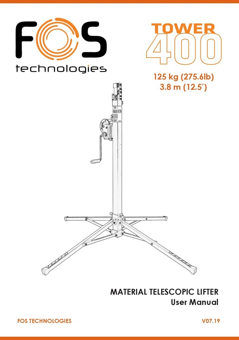
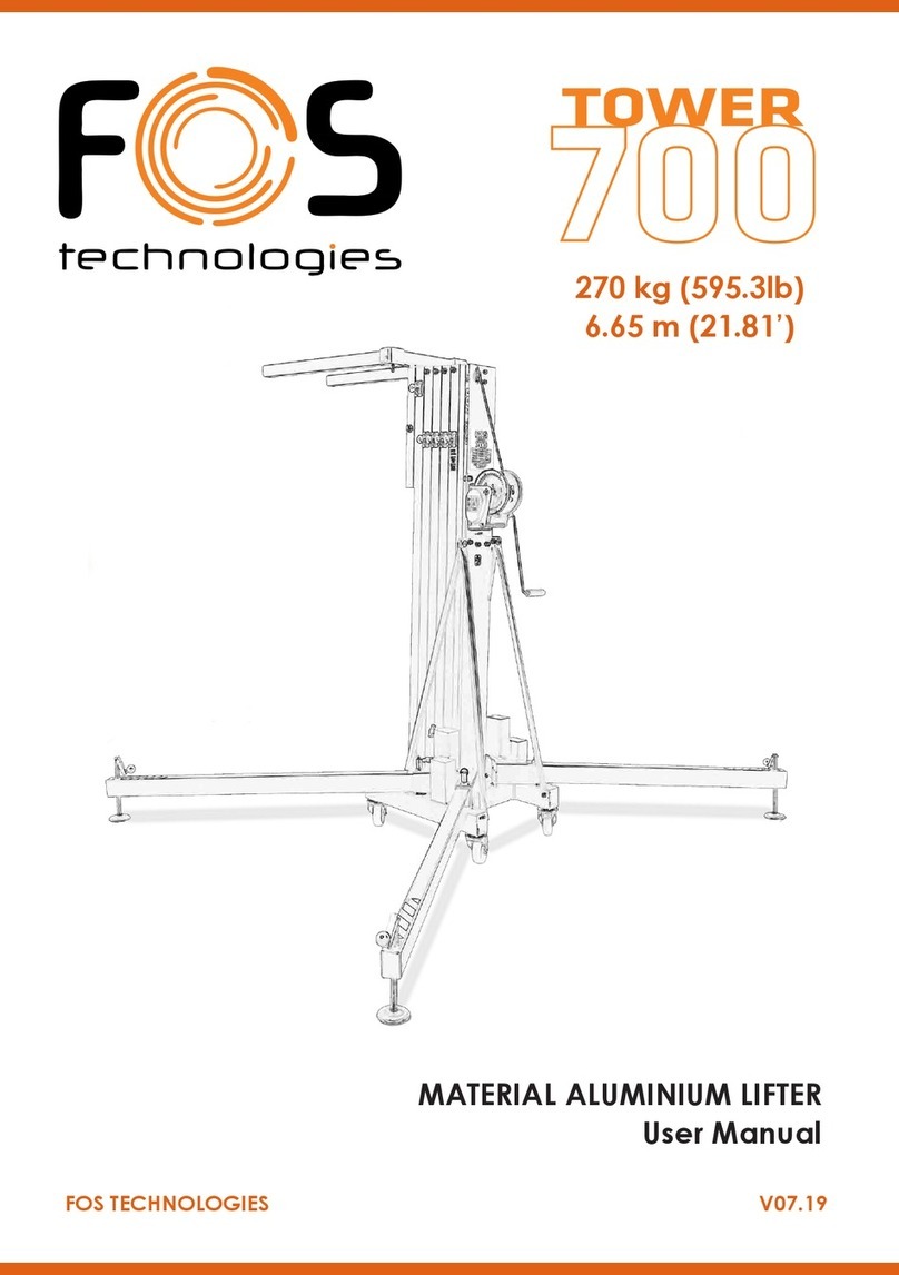
FOS Technologies Tower 650 User manual

FOS TECHNOLOGIES V07.19
MATERIAL TELESCOPIC LIFTER
User Manual
220 kg (485lb)
6.5 m (21.3’)

2
FOS 650
F1313K
F1316K
F1314K
Section 1 (Base)
Section 2
Section 4
F4003K
Winch
A
B
C
F2121K
Leg
F1207K
Leg cap
F1312K
Section 3
F1315K
Section 5

3
FOS 650
A
A.5
A.6
F2183K
FOS Lock
A.1
A.1
Left Right
A.7
F2184K
A.2
A.3
F1015K
Screw
A.1 A.2 A.3
LOCK F2183K F2183K F2184K
Left
F1061K F7005K F2124K F1061K F7005K F2124K F1062K F7005K F2124K
(x2) (x2) (x2) (x2) (x2) (x2)
Right
F1061K F7005K F2124K F1012K F1012K
(x2) (x2) (x2) (x2)
F2126K
F2125NK F1020K F8001K
F1020K F8001K
F1116K
A.4
A.4

4
FOS 650
A.7
F2004K
F8004K
F1019K
F7006K
F2125K
F1104K
F2126K
F1105K
F1018K
A.5
F2006K
F8004K F1019K
F7006K
F2125K
F1106K
F2126K
F1105K
F1020K
F1018K
F8001K
A.6
F1020K
F1020K
F8001K
F8001K
F2007K
F8004K F1019K
F7006K
F2125K
F1109K
F2130K
F1110K
F1020K
F1018K
F8001K
F1020K F8001K
F1020K F8001K

5
FOS 650
BF7010K Nut
F1014K
Screw
F5005K
B.1
B.2
F1024K
F3004K
F2006K
F1023K
F1108K
F1005K
F1005K
F1024K
F3005K
F2008K
F1023K
F1111K
F1005K
F1005K
B.3
F1024K
F1023K
F1107K
F1005K
F1005K
F2004K
F3003K
Wheel

6
FOS 650
F4003K
Winch
F1021K
F8003K
Screw
Washer
F7006K
F8004K
D.1
F9005K
Steel cable F2127K
Cable clamp
F1022K
F2004K F8009K
F2119K
Spirit level
D
D.1
C
F2115K
F7003K
F2116K
F1006K F8004K
F2117K
F8005K
F1012K
F2129K
F1011K
F7004K
F2128K
Complete stabilizer kit

7
FOS 650
Code/Código Description/Descripción
F1005K Conic screw M6x16 / Tornillo avellanado M6x16
F1006K Allen screw M10x25/ Tornillo allen M10x25
F1011K Allen screw M5x25 / Tornillo allen M5x25
F1012K Allen screw M6x10 / Tornillo allen M6x10
F1014K Hexagonal taptite screw / Tornillo hexagonal taptite
F1015K Allen screw M12x25 / Tornillo allen M12x25
F1018K Allen screw M6x25 / Tornillo allen M6x25
F1019K Special M12 screw / Tornillo especial M12
F1020K Allen screw M8x25 / Tornillo allen M8x25
F1021K Allen screw M10x20 / Tornillo allen M10x20
F1022K Hexagonal screw M12x40 / Tornillo hexagonal M12x40
F1023K Conic screw M6x35 / Tornillo cónico M6x35
F1024K Conic screw M6x35 / Tornillo cónico M6x35
F1061K Headless allen screw M6x25 / Tornillo allen sin cabeza M6x25
F1062K Headless allen screw M6x20 / Tornillo allen sin cabeza M6x20
F1104K Pulley support plate Ø 60 / Pletina portapoleas Ø 60
F1105K Interior plate / Pletina interior
F1106K Pulley support plate Ø 80 / Pletina portapoleas Ø 80
F1107K Axel plate 60 / Pletina eje 60
F1108K Axel plate 80 / Pletina eje 80
F1109K Pulley support plate Ø 55 / Pletina portapoleas Ø 55
F1110K Interior plate / Pletina interior
F1111K Axel plate 100 / Pletina eje 100
F1116k Interior steel piece / Pletina interior roscada de acero
F1207K Legprole/Perlpata
F1312K Section 3 K-6 / Tramo 3 K-6
F1313K Section 2 K-6 / Tramo 2 K-6
F1314K Section 1 (Base) K-6 / Tramo 1 (Base) K-6
F1315K Section 5 K-6 / Tramo 5 K-6
F1316K Section 4 K-6 / Tramo 4 K-6
F2004K Pulley Ø 60 / Polea Ø 60
F2006K Pulley Ø 80 / Polea Ø 80
LISTA DE REPUESTOS / SPARE PARTS LIST

8
FOS 650
F2007K Pulley Ø 55 / Polea Ø 55
F2008K Pulley Ø 90 / Polea Ø 90
F2115K Stabilizer ball / Bola del estabilizador
F2116K Stabilizer handle / Manivela estabilizador
F2117K Stabilizer plate Ø 80 / Plato estabilizador Ø 80
F2119K Spirit level indicator / Nivel de burbuja
F2121K 50x50 leg tap / Tapón pata 50x50
F2124K Lock runner / Patín de gatillo
F2125K M10x35 knob / Palomilla LARGA Kuzar
F2125NK M10x20 knob / Palomilla CORTA Kuzar
F2126K Nylon rest / Taco de nylon
F2127K Cable clamp screw Ø6 mm / Prisionero cable Ø6 mm
F2128K Complete stabilizer / Estabilizador completo
F2129K Threaded bolt M16 / Esparrago M16
F2130K Nylon rest / Taco nylon
F2183K KAT Lock K-6 / Gatillo KAT K-6
F3003K 12x60 Axel / Eje 12x60
F3004K 12x80 Axel / Eje 12x80
F3005K 12x100 Axel / Eje 12x100
F4003K 450 Kg Winch with long handle / Cabrestante 450 Kg manivela larga
F5005K Ø100 blue wheel with 4 screws plate / Rueda Ø100 plato 4 taladros
F7003K Nut M10 / Tuerca M10
F7004K Auto-block nut M5 / Tuerca autoblocante M5
F7005K Nut M6 / Tuerca M6
F7006K Auto-block nut M12 / Tuerca autoblocante M12
F7010K Auto-block nut M6 / Tuerca autoblocante M6
F8001K Flat M8 washer / Arandela plana M8
F8003K Flat M10 washer / Arandela plana M10
F8004K M12 washer / Arandela M12
F8005K Wide M6 washer / Arandela M6 ancha
F8009K Flat M14 washer / Arandela M14 plana
F9005K Cable K-6 (Ø6 mm) / Cable K-6 (Ø6 mm)
LISTA DE REPUESTOS / SPARE PARTS LIST

9
FOS 650
Operating Instructions
1 - INTRODUCTION.
Dearuser.ThankyoupurchasingyourFOS650lifter.Wehopeyouwillbeverysatised
with it.
This manual has been written so that you can understand how to effectively use the lift
and most importantly, so that you can use it safely.
It is important that you fully read the manual and follow the instructions carefully before
using your lift. All FOS lifts undergo a very strict quality control process during their
manufacture. So that your lift always works properly please only purchase original FOS
parts from an authorized distributor or dealer. The user waives all warranty rights if using
parts other than FOS or if the product is manipulated in any way by an unauthorized third
party. When requesting parts, please refer to the diagrams in the back of this manual and
quote the serial number and year of manufacture located on your lifter.
2.- TECHNICAL SPECIFICATIONS.
The FOS 650 has been designed for vertically lifting lighting, trussing etc in the Profes-
sional sound and light sector. There is various supports or accessories available, please
refer to our website or catalogue.
2.1 - Max. load: 220 kg (485 lb)
2.2 - Min. load: 25 kg (55 lb)
2.3 - Max. height: 6.5 m (21.32’)
2.4 - Folded height: 1.82 m (5.97’)
2.5 - Work surface: 2.56 x 2.56 m (8.4’ x 8.4’)
2.6 - Folded base area: 47 cm x 47 cm (1.5’ x 1.5’)
2.7 - Weight: 90 Kg (198.4 lb)
2.8-Winch:450kgcertied(LongHandle)
2.9 - Cable: Steel DIN 3060. Tensile strength 180 kg/mm2. Anti-torsion & anti-corrosion
6 mm cable diameter.
2.10-Constructionmaterial:SteelprolesEN10305.
2.11 - Antirust protection priming paint bathed black steel, covered with cured polyester
dust.
2.12-Five-proletelescopicsystemoperatedbysteelcabledrivenbypulleyswithmetal
protected bearing pads. Adaptor Ø35 mm.

10
FOS 650
Operating Instructions
2.13 - FOS Locks on each section which automatically slots in to the sections during
elevation, locking them in place.
2.14 - Anchor of the legs by safety catches.
2.15 - Adjustable stabilizer plates in the legs with nonslip rubber base support.
2.16 - Spirit level for vertical alignment.
2.17 - Swivel wheels for transporting the lifter to its working position.
3. - SAFETY GUIDELINE.
3.1.-Situatethetoweronasolidandatsurface.
3.2.- Check that the legs are fully inserted and secured in to their housing with the safety
locks.
3.3.- Ensure that the lifter is in a vertical position and use the spirit level located on the
baseproletocheck.Ifnecessary,adjustitsalignmentwiththeplatesbyturningthe
handle in the appropriate direction.
3.4.- Check that the tower is locked in its working position with the safety lock.
3.5.- When used outdoors, place the tower on a hard surface and if necessary secure it
against excess wind force via cable braces.
3.6.- Do not use ladders nor lean them against the lifter.
3.7.- Be careful with any cables, prominent objects etc. placed above the tower.
3.8.- Do not stand underneath the load.
3.9.- Do not move the tower when it is elevated or loaded.
3.10.- Before using the tower, check the condition of the cable. This must be free of cuts
and frays. Never use damaged cables.
3.11.- Never dismount the winch handle or any element of the winch under any
circumstance.
3.12.- Once the tower is set-up in its working position we recommended the
winch handle is locked to avoid anyone interfering with it.
3.13.- The minimum load for a safe operation of the brake is 25 kg. The brake will not
function without this minimum load.
3.14.- Do not grease or lubricate the brake mechanism of the winch.
3.15.- This lift cannot lift human beings,

11
FOS 650
Operating Instructions
3.16.-Fortransportationitisnecessarytoretractallprolesandlockthemwiththe
corresponding safety lock.
4. - OPERATION.
4.1.-Placethetoweronaatandsolidsurfacewhereitisgoingtobeused.
4.2.- Remove the legs from their support brackets and insert them in their working
position.Checkthattheyarefullyinsertedandxedwiththesafetylock.
4.3.- Ensure that the lifter is in a vertical position and use the spirit level located on the
baseproletocheckthebubbleiscentred.Ifnecessary,adjustitsalignmentwiththe
stabiliser plates by turning the handle in the appropriate direction.
4.4.- Attach the load to the tower using the desired support (the support varies upon the
application), and ensure it is only used to lift loads vertically. The minimum load is 25 kg.
4.5.- Elevation: Extend the tower by turning the winch handle clockwise, lifting the load
to the desired height.
4.6.- Hold: Release the winch handle, it will remain in position by the action of the
winch’sautomaticbrake.EnsuretheFOSlockhasintroducedintotheprolebyturning
the handle slightly anti-clockwise.
4.7.- Continue elevating: Turn the winch handle again clockwise and lift the load until
the next prole is fully extended. Release the handle which will remain xed by the
winch’s automatic brake and ensure again the FOS lock has introduced into the second
prolebyturningthehandleagainanti-clockwise.Thetowercanbestoppedinanydesi-
red intermediate position. Simply release the winch handle and secure the tower by in-
serting the corresponding FOS lock into the hole which is closest to the required position.
4.8.- Descent: Firstly unlock the safety lock and turn the winch handle anti-clockwise
untiltheintermediateproleiscompletelyfoldeddown.NowunlockthenextFOSlock
andretractthefollowingprole.Justaswhenliftingtheload,theliftmaybestoppedat
any intermediate position.
4.9.- Transport: Four swivel wheels are located at the base for transporting the lifter. Be-
foretransportitisnecessarytofolddownthetowerbyretractingitsprolescompletely.
Dismount the legs by releasing the safety locks and place them back in their transport
compartments.

12
FOS 650
Operating Instructions
5.- MAINTENANCE.
5.1.- All cables must be checked regularly. Faulty cables must be replaced immediately.
Do not use the lifter with faulty cables as it is potentially very dangerous. Only use DIN
3060 cables, supplied from an authorised dealer.
5.2.- The lifter is delivered ex factory completely greased. Depending on its mechanical
Use though, we recommend that the crown wheel of the winch, the pads & bushings
ofthedriveshaft,thehandlethreadandtheprolesoftheliftareperiodicallygreased.
ATTENTION:
Do not apply oil or grease to the brake mechanism. The brake discs have been pre-grea-
sed with a special heat and pressure resistant grease. To avoid malfunction to the winch
brake, no other products must be used except the original provided by the company. It
is not necessary to grease the brake discs.
5.3.- Your lifter should be inspected at least once a year by a specialized / authorized
service centre.
5.4.- Only original FOS spare parts must be used to guarantee the reliability and opera-
tional safety of your lifter. The user shall lose all warranty claims if he uses anything other
thanoriginalsparepartsormodiesthisproductinanyway.
5.5.- In case a spare part is required please indicate the reference number which can be
found in the spare parts list at the back of this manual.
6.- WARRANTY.
All FOS lifts come with 2 years warranty. This warranty period is from the date of pur-
chase. FOS will repair any defect product caused by either faulty materials or poor work-
manshipfreeofchargewithinthisperiodaslongasthepartsarettedbyanauthorized
FOS dealer. Should the product have been manipulated in any way or a repair attempted
by an unauthorized dealer the warranty will be invalid. This warranty does not cover da-
mage occurred by improper use.
7.- CERTIFICATIONS
FOSreservestherighttomakeanymodication/alterationtotheliftwithoutpriornotice.
Anymodication/alterationwouldbeaninnovation,intendedtoimprovetheproduct.

13
FOS 650

14
FOS 650

15
FOS 650

FOS Technologies LTD
Bulevard Iliensko Shose 8
SladovaBazaZMM,Soa,BG
www.fos-lighting.eu
Call Center : +30 2102811700
This manual suits for next models
1
Table of contents
Other FOS Technologies Lifting System manuals
Popular Lifting System manuals by other brands
JLG
JLG 3507 Supplemental repair manual
Denios
Denios SV manual
AMF-BRUNS
AMF-BRUNS HUBMATIK K90 operating instructions

HSS Hire
HSS Hire 69313 Operating & safety guide
WERTHER INTERNATIONAL
WERTHER INTERNATIONAL PRM50 manual

Custom Equipment
Custom Equipment HY-BRID LIFTS HB-P3.6 MAINTENANCE & TROUBLESHOOTING MANUAL
EZ-ACCESS
EZ-ACCESS PASSPORT user manual
Dino lift
Dino lift DINO 125T Operation & instruction manual
JLG
JLG E600 Service and maintenance manual
Launch
Launch TLT235SC user manual

ShoulderDolly
ShoulderDolly HandyLifter instruction manual

AAQ
AAQ AutoLift AL-1132-220 Installation manual & operation instructions
