Foss Infratec 1241 User manual

Copyright 2011 / All rights reserved
FOSS Analytical A/S, Foss Allé 1, DK-3400 Hillerød, Denmark
Infratec™ 1241 Grain Analyzer
Service Manual
1001 5015 / Rev. 4

Infratec™ 1241 Grain Analyzer
Service Manual 1001 5015 / Rev. 4
Information may be changed or updated without notice. The latest version is found at www.foss.dk.
Rev. Date of Issue Revised Material
1 2011-03-18 First issue
2 2012-11-09 Service procedure updated
3 2015-05-18 General update
4 2016-09-26 Minor changes in section 1, 4 and 5

Infratec™ 1241 Grain Analyzer
Service Manual 1001 5015 / Rev. 4
Table of Contents
1 Important Instructions .............................. 1:1
1.1 General ........................................................................ 1:1
1.2 Service Documents ................................................... 1:1
1.3 Self-Service Support ................................................. 1:1
1.4 Contacting Customer Support ............................... 1:1
1.5 ESD Information ........................................................ 1:1
1.6 Precautions ................................................................. 1:2
2 Technical Description................................. 2:1
2.1 History ......................................................................... 2:1
2.2 Component Descriptions ......................................... 2:3
2.2.1 PC-Module ..................................................................... 2:4
2.2.2 Processor Board ............................................................ 2:5
2.2.3 DSP Board ...................................................................... 2:6
2.2.4 CompactFlash Disk ........................................................ 2:8
2.2.5 Monochromator ........................................................... 2:8
2.2.6 Lamp Module .............................................................. 2:10
2.2.7 Detector ...................................................................... 2:11
2.2.8 Power Supply .............................................................. 2:12
2.2.9 LCD Display ................................................................. 2:14
2.2.10 Display Interconnection Board .................................. 2:15
2.2.11 Electronic ID ................................................................ 2:15
2.2.12 TWM (Optional) .......................................................... 2:16
2.2.13 STM (Optional) ............................................................ 2:18
2.2.14 Remote I/O (Optional) ................................................ 2:19
2.3 Software Description ............................................. 2:22
3 Installation ................................................. 3:1
3.1 General ........................................................................ 3:1
3.2 Installation of Test Weight Module on
Infratec 1241 Generation 2 ..................................... 3:1
3.2.1 Preparation of the Infratec for assembly .................... 3:1
3.2.2 Preparation of the Test Weight Module for assembly 3:4
3.2.3 Final assembly of Infratec and Test Weight Module into a
complete assembly ....................................................... 3:6
3.3 Installation of Test Weight Module on
Infratec 1241 Generation 3 ................................... 3:10
3.4 Installation of Sample Transport Module ......... 3:21

Infratec™ 1241 Grain Analyzer
Service Manual 1001 5015 / Rev. 4
3.5 Mosaic Connection .................................................. 3:22
4 Diagnostics and Troubleshooting .............4:1
4.1 General ......................................................................... 4:1
4.1.1 Poor Results ................................................................... 4:2
4.1.2 User Problems ................................................................ 4:2
4.1.3 Poor Calibrations ........................................................... 4:2
4.1.4 Outliers .......................................................................... 4:2
4.1.5 Poor Reference Data ..................................................... 4:3
4.1.6 Instrument Problems ..................................................... 4:4
4.1.7 I2C Trouble Shooting .................................................... 4:4
4.2 Service Menu ............................................................ 4:10
4.3 Quality Control ......................................................... 4:12
4.3.1 Self-test ........................................................................ 4:12
4.3.2 Clean Measuring Unit ................................................. 4:19
4.3.3 Audit Log ..................................................................... 4:19
4.3.4 Software Error Log ...................................................... 4:19
4.3.5 Hardware Error Log .................................................... 4:20
4.3.6 Export Logs and Configuration .................................. 4:20
4.3.7 Wavelength Stability .................................................. 4:20
4.3.8 Lamp Check ................................................................. 4:20
4.4 Automatic Tests ....................................................... 4:21
4.4.1 Detector ....................................................................... 4:21
4.4.2 Monochromator .......................................................... 4:22
4.4.3 I/0 (Input/Output) ........................................................ 4:23
4.5 Manual Tests ............................................................. 4:25
4.5.1 Detector ....................................................................... 4:25
4.5.2 Monochromator .......................................................... 4:25
4.5.3 Measuring Unit ........................................................... 4:26
4.5.4 Display ......................................................................... 4:26
4.5.5 Scan .............................................................................. 4:26
4.5.6 Test Weight ................................................................. 4:27
4.5.7 Sample Transport Module .......................................... 4:27
4.6 Manual Analysis ....................................................... 4:28
4.6.1 Settings ........................................................................ 4:28
4.6.2 Fill Sample Cell ............................................................ 4:28
4.6.3 Scan .............................................................................. 4:28
4.6.4 Offset ........................................................................... 4:28
4.6.5 Empty Sample Cell ...................................................... 4:28
4.6.6 Flush Sample Cell ........................................................ 4:28
4.7 Instrument Info ........................................................ 4:29
4.7.1 Hardware ..................................................................... 4:29

Infratec™ 1241 Grain Analyzer
Service Manual 1001 5015 / Rev. 4
4.7.2 Software ...................................................................... 4:29
4.7.3 BIOS ............................................................................. 4:29
4.7.4 Monochromator Constants ........................................ 4:29
4.7.5 Operating Temperature ............................................. 4:29
4.7.6 Volume Information ................................................... 4:29
4.7.7 Voltage Information ................................................... 4:29
4.8 Clone Instrument .................................................... 4:29
4.9 Settings ..................................................................... 4:30
4.9.1 Default Settings .......................................................... 4:30
4.9.2 Scan Mode (Standard) ................................................ 4:30
4.10 Read Disk ................................................................... 4:30
4.11 Error Codes in Software Log (SL) and Hardware
Log (HL) ...................................................................... 4:31
4.11.1 Error 4, Grating Motor Error ...................................... 4:33
4.11.2 Error 22, MU/TWM Data Range Error ........................ 4:33
4.11.3 Error 32, Speckle Signal Blocked ................................ 4:33
4.11.4 Error 128, Path Length Error ...................................... 4:34
4.11.5 Error 512, Speckle Function Error .............................. 4:34
4.11.6 Error 16384, Strain Gauge Failure (Load Cell) ........... 4:34
4.11.7 Error 32768, Hardware Error ...................................... 4:34
4.11.8 Error 33292, Reference Scan too low ........................ 4:35
4.11.9 Error 33293, Too few valid Sub samples collected ... 4:35
4.11.10 Error 33294, Monochromator Shutter not able
to move ....................................................................... 4:35
4.12 Hardware Error Log (xxxxxxxx.HL) ..................... 4:36
4.12.1 Error Word .................................................................. 4:36
4.12.2 Commands .................................................................. 4:37
4.12.3 Status Word 1 ............................................................. 4:41
4.12.4 Status Word 2 ............................................................. 4:42
4.12.5 Error Word 1 ............................................................... 4:43
4.12.6 Error Word 2 ............................................................... 4:44
4.12.7 Error Word 3 ............................................................... 4:45
4.12.8 Error Word 4 bit encoding (0x0108) .......................... 4:45
4.12.9 DSP Version ................................................................. 4:45
4.13 Export Logs and Configuration ........................... 4:46
5 Service and Maintenance .......................... 5:1
5.1 Special Tools ............................................................... 5:1
5.2 Service Procedures .................................................... 5:1
5.2.1 Replacement of Display Kit .......................................... 5:1
5.2.2 Replacement of Keyboard Overlay .............................. 5:7
5.2.3 Replacement of Detector Unit Complete .................... 5:8

Infratec™ 1241 Grain Analyzer
Service Manual 1001 5015 / Rev. 4
5.2.4 Replacement of Monochromator Complete ............... 5:9
5.2.5 Replacement of Halogen Lamp for Monochromator 5:11
5.2.6 Use of the Aperture Kit (p/n 60023539) .................... 5:13
5.2.7 Replacement of Power Supply Board ........................ 5:16
5.2.8 Replacement of Interface Complete .......................... 5:18
5.2.9 Replacement of PC Module Complete w/o
Flash Disc ..................................................................... 5:23
5.2.10 Replacement of DSP Board ......................................... 5:29
5.2.11 Replacement of Compact Flash Disc .......................... 5:35
5.3 Measuring Unit ......................................................... 5:36
5.3.1 General ........................................................................ 5:36
5.3.2 Replacement of Measuring Unit Complete ............... 5:36
5.3.3 Replacement of Upper Solenoid ................................ 5:38
5.3.4 Replacement of Lower Solenoid ................................ 5:39
5.3.5 Replacement of Lower Linkage Shutter Assembly ... 5:40
5.3.6 Replacement of Upper Linkage Shutter Assembly ... 5:41
5.3.7 Replacement of Connection PCB Complete .............. 5:42
5.3.8 Replacement of Measuring Unit PCB ......................... 5:43
5.3.9 Replacement of Variable Motor ................................ 5:44
5.3.10 Replacement of Conveyor Motor ............................... 5:45
5.3.11 Replacement of Cell Wall Front with Speckle
Emitter PCB .................................................................. 5:46
5.3.12 Replacement of Cell Block Complete and Path Length
Encoder ........................................................................ 5:47
5.3.13 Replacement of Cell Cover Outer .............................. 5:48
5.3.14 Checking movement of the Variable Cell .................. 5:49
5.3.15 Drawer Sensor Cable, rerouting ................................. 5:50
5.4 Test Weight Module ................................................ 5:52
5.4.1 Replacement of Test Weight Balance Complete ....... 5:52
5.4.2 Replacement of Wiper Arm Complete ...................... 5:53
5.4.3 Replacement of TWM PCB .......................................... 5:56
5.4.4 Replacement of Wiper/Shutter Motor ....................... 5:58
5.4.5 Replacement of Locking Guide .................................. 5:61
5.4.6 Checking/Adjusting TWM Level Sensors .................... 5:63
5.5 Sample Transport Module ..................................... 5:65
5.5.1 Replacement of Cuvette Glass Kit .............................. 5:65
5.5.2 Replacement of STM Cuvette Cam Thread ................ 5:66
5.5.3 Checking STM Cuvette Cam Thread ........................... 5:69
5.6 Corrective Maintenance Procedures ................... 5:70
5.6.1 Cable Stalk Kit ............................................................. 5:70
5.6.2 Lamp Holder ................................................................ 5:70
5.6.3 DSP board .................................................................... 5:70
5.6.4 TWM PCB ..................................................................... 5:70

Infratec™ 1241 Grain Analyzer
Service Manual 1001 5015 / Rev. 4
5.7 Preventive Maintenance Procedures .................. 5:72
5.7.1 Measuring Unit Adjustment of Path Length ............ 5:72
5.7.2 TWM Balance Calibration .......................................... 5:74
5.7.3 TWM balance Control ................................................ 5:77
6 Technical Specifications............................. 6:1
7 Schematics .................................................. 7:1
8 Document References................................ 8:1


Infratec™ 1241 Grain Analyzer
Service Manual 1001 5015 / Rev. 4 1:1
1 Important Instructions
1.1 General
This Service Manual contains descriptions, installation instructions, maintenance
instructions, troubleshooting, specifications and schematics for the Infratec™ 1241
ISW 5.xx. Service of Infratec™ 1241 should only be done by authorized personnel.
NOTE: This manual covers the Infratec 1241 Generation 2 and 3
only. For reference to the Infratec 1241 Generation 1 and Infratec
1256 use Service Manual p/n 10012177.
1.2 Service Documents
This Service Manual is a part of the Service USB (if available) which contains the
complete support documentation for this product. The Service USB may contain
additional information in the form of animations for the purpose of illustrating and
explaining e.g. working principles, process flows and service and adjustment
procedures. See also section 8 Document References for an overview of User and
Service Documentation.
1.3 Self-Service Support
The Customer Support Toolbox (CST) on FOSS EXTRAnet (www.foss.dk) contains
all available support information. Please visit the CST at regular intervals for latest
updates of documents and software.
1.4 Contacting Customer Support
For support on this product, please contact the responsible Technical Support
engineer at FOSS or file a support request in the Global HelpDesk on FOSS
EXTRAnet.
1.5 ESD Information
Parts of this instrument, e.g. PCBs, are sensitive to Electro Static Discharge (ESD).
All sensitive parts should be handled using ESD protection.
Follow these rules for effective ESD protection:
• Handle all ESD sensitive parts with an ESD wrist band connected to earth.
• Transport all ESD sensitive parts in ESD protected bags or boxes.
• Check your ESD protection at regular intervals to secure its function and quality.

Infratec™ 1241 Grain Analyzer
1:2 Service Manual 1001 5015 / Rev. 4
The following ESD protection material is available from FOSS:
• 436220 Field-ESD service kit including wrist band
• 463238 Blue table mat with wrist strap and ground wire
• 436246 Coiled wire, 360 cm with stretch-wrist band
• 436261 Wrist-strap tester
Fig. 1:1 ESD equipment
1.6 Precautions
The layout of safety symbols used in this manual is described below. Symbols are
used whenever a safety related message is written to warn the reader of potential
hazards.
Safety Symbols
Explanation of safety symbols used in this manual:
Safety Terminology
Explanation of safety terms used in this manual.
Symbol Description
General hazard.
Electrical shock hazard.
Hot surface.
Heavy object.
Term Description
Warning Danger to human safety.
Caution Danger to product performance/operation.
Note Important supplementary information.
8000189a

Infratec™ 1241 Grain Analyzer
Service Manual 1001 5015 / Rev. 4 2:1
2 Technical Description
2.1 History
The Infratec 1241 was first launched in the year 2000. It was then equipped with a
black & white display and a diskette drive as means of importing and exporting data
to the instrument. These instruments are now referred to as Generation 1.
In 2007 the Infratec 1241 was hardware and software wise redesigned. It was then
equipped with a color display and USB ports for importing and exporting data. The
"Basic concept" was also introduced which made it possible to limit the amount of
calibrations on the instrument and thus reduce the selling price. These instruments
are now referred to as Generation 2.
In 2010 the exterior was redesigned to match the EyeFoss image analyzer design.
Few internal parts where altered. These instruments are now referred to as
Generation 3.
The Infratec 1256 is electronically and technology wise almost identical to the 1241.
Over the years different hardware and software features have been continuously
introduced, e.g. TCP/IP, calculated constituents. Many ofthese can be added to older
instruments. Upgrade of ISW is always free of charge.
The Basic Concept
Model Display Data ISW version
Generation 1 Black & white Diskette 3.xx
Generation 2 Color USB 5.xx
Generation 3 Color USB 5.xx
Model # of allowed AppM's # of allowed parameters
Full Many Many
Basic 1 One Three
Basic 2 Two Three per AppM
Basic 3 One Six
Basic 4 Two Four per AppM
Basic 5 Five Four per AppM
Basic 6 Six Four per AppM

Infratec™ 1241 Grain Analyzer
2:2 Service Manual 1001 5015 / Rev. 4
Related Information
Service personnel should be familiar with the following documentation:
• User Manual; for function descriptions, maintenance and operating instructions
• Spare Parts Manual; for spare part illustrations and spare part numbers
• Quick Guide; for a quick start instruction
Also see chapter 8 Document References.
Abbreviations
Explanation of abbreviations used in this manual.
ADC Analog to Digital Converter
DIB Display Interconnection Board
DSP Digital Signal Processing
EID Electronic ID
GA Grain Analyzer
I2C Standardised serial interface (Inter Integrated Communication)
I/O Input/Output
ISW Instrument Software
LIMS Laboratory Information and Management System
MU Measuring Unit
OS Operating System
PCB Printed Circuit Board
PSM Power Supply Module
RTOS Real Time Operating System
STM Sample Transport Module, optional
TWM Test Weight Module, optional

Infratec™ 1241 Grain Analyzer
Service Manual 1001 5015 / Rev. 4 2:3
2.2 Component Descriptions
Compatibility with previous version
System Overview
Fig. 2:1
Module Compatible Comments
PSU Yes All versions
Detector Yes All versions
Monochromator Yes All versions
MU Yes All versions
TWM Yes All versions (TN 1234)
STM Yes
LCD Display No See Spare Parts Manual
PC module
DSP
PC- board
Compact Flash
Floppy disk
No
No
No
No/Yes
No
Requires OS vers 5.01 or higher
Requires OS vers 5.01 or higher
Dependency. Requires ISW 5.xx
Disabled in BIOS, USB Floppy disk support
Cable Stalk No
Interface No USB
Chassis Yes
Infratec™ 1241 Grain Analyzer
2:4 Service Manual 1001 5015 / Rev. 4
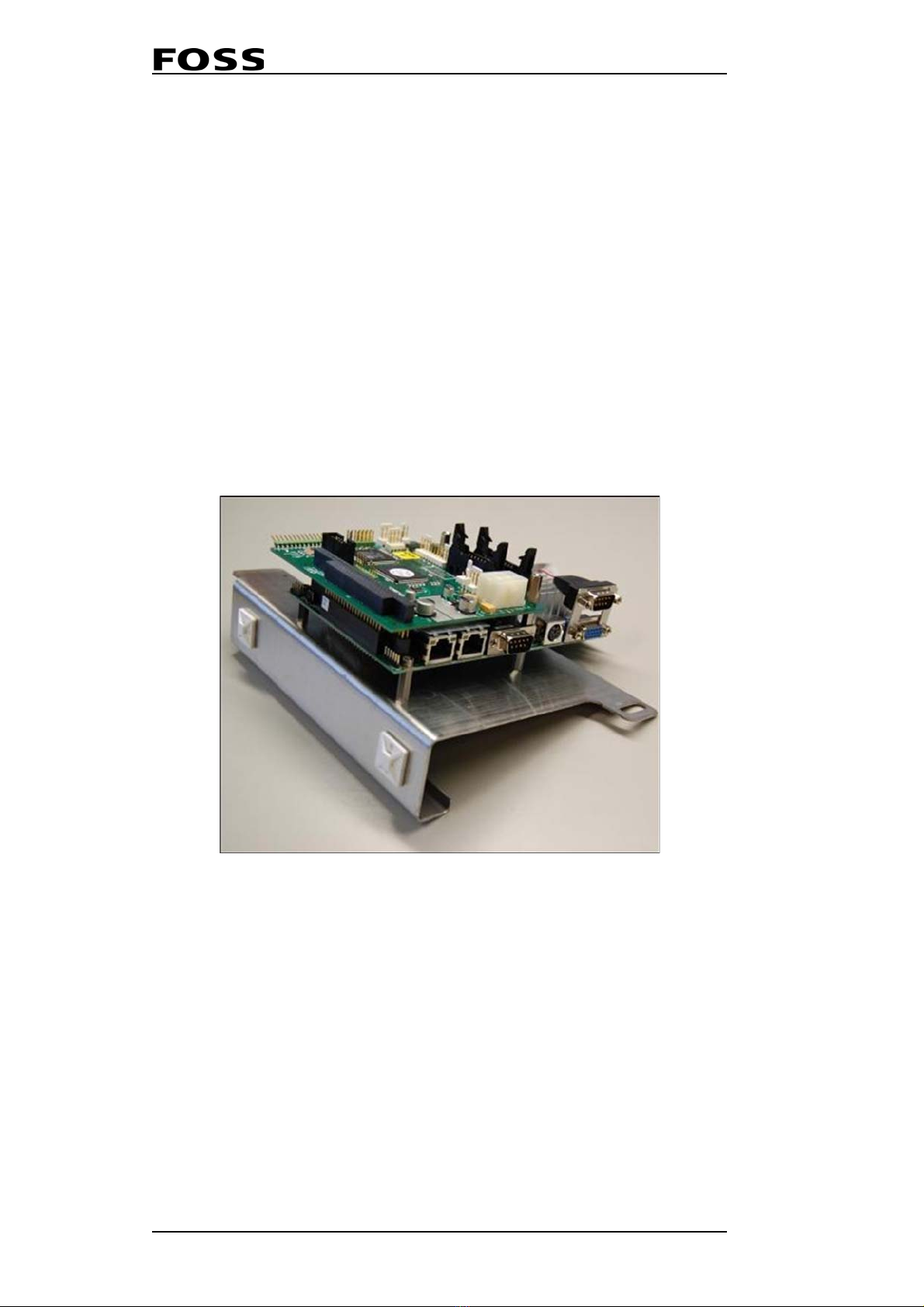
2.2.1 PC-Module
The PC-module is a PC104 embedded hardware platform with QNX real-time
operating system (RTOS). PC104 is a popular standardized form-factor for small
computing modules typically used in embedded system. A system composed of PC/
104 modules is often referred to as a "stack".
The PC module "stack" assembly consists of:
• Mounting plate
• Processor board, that acts as a controller for the peripheral components
• DSP board, that acts as an extension Processor board and is also used as an I/O
system
Communication between the PC-module and the instrument modules is routed via
the DSP board I2C bus, which is a simple standard 2-wire connection where the DSP
acts as the master device.
NOTE: Due to the QNX software platform, USB plug & play is not
supported. An USB-floppy drive solution may however work.
Fig. 2:2 PC-Module

Infratec™ 1241 Grain Analyzer
Service Manual 1001 5015 / Rev. 4 2:5
2.2.2 Processor Board
The processor board is a single board processor (SBC) with an onboard CPU
processor. Processor board acts as a controller for the peripheral components. The
processor board communicates with the DSP board via the PC/104 bus.
The processor board has three main interfaces:
• DSP board PC/104 bus
• TFT LCD display
• Connectors to chassis Interface panel, providing access to external keyboard,
USB, comm. ports, LAN etc
Fig. 2:3 Processor Board
CN3 Printer Interface (LPT1) CN15 LAN/Ethernet Interface
CN5 USB Interface (0&1) CN18 Keyboard/Bar code Interface
CN12 LCD Display CN19 COM1 Interface
CN13 COM2 Interface CN20 CRT Monitor Interface

Infratec™ 1241 Grain Analyzer
2:6 Service Manual 1001 5015 / Rev. 4
The Processor Board has replaceable external CMOS battery.
Fig. 2:4 Processor Board
2.2.3 DSP Board
The DSP module is accessed from the ISW via the PC/104 bus interface (P3) and acts
as slave under the ISW.
The DSP software acts as an extension of the ISW and is also used as an I/O system.
The PC-module makes it possible for the ISW to have control over the different HW
modules.
There is no ROM memory on the DSP Board. For this reason, the DSP software is
uploaded from the processor board by ISW during start-up. The ISW installation
package contains and installs the latest and matching DSP software version.
The DSP has an I2C bus interface, implemented as a SW driver in the DSP software
and is used for communication between devices inside the instrument. I2C is a two-
wire serial bus, as shown in Fig. 2:5.
Fig. 2:5
There are a number of on board LEDs on the DSP Board. These LEDs provide
information as to the status of the DSP Board.
LED Function Color
D3 Power On Green, constant
D4 DSP-ISW communication Red, flashing when active
D1 DSP running Red, constant after boot-up
D2 Monochromator motor
direction Red, blinking

Infratec™ 1241 Grain Analyzer
Service Manual 1001 5015 / Rev. 4 2:7
Fig. 2:6 DSP Board
P1 Keypad P13 Detector
P3 PC/104 Bus P14 I2C Bus
P6 Power Supply P15 I2C Bus
P7 Inverter Interface Board D1 DSP running (red LED)
P8 Monochromator D2 Monochromator (red LED)
P9 Monochromator D3 Power On (green LED)
P12 Monochromator D4 I2C communication (red LED)
DSP Board
From Designation To
P1 Keypad overlay
P3 PC/104 Bus Interface Processor Board
P6 Power Supply Power Supply Board (P7)
P7 Backlight Power Display Interconnection Board
P8 Encoder Connector Monochromator
P9 Grating Motor Connector Monochromator
P12 Shutter Board Connector Monochromator
P13 Detector Signal Detector
P14 I2C Bus Measuring Unit

Infratec™ 1241 Grain Analyzer
2:8 Service Manual 1001 5015 / Rev. 4
2.2.4 CompactFlash Disk
Type II CompactFlash™ Memory
The CompactFlash memory is preinstalled with latest OS version and ISW software.
As spare part it is available as Basic 1 configuration only.
The Flash Disk is an electronic memory mounted in a slot on the Processor Board.
Due to market conditions you may find different sizes in the instruments over the
years. There is no problem upgrading the Flash Disk to a larger size. The disk is
partitioned in three parts, 5 Mb for the operative system, 5 Mb for ISW. The
remaining space is for data.
The Basic Concept
2.2.5 Monochromator
The Monochromator is developed and manufactured by FOSS. It is to be considered
a closed, factory calibrated box. There is under no circumstance any reason to open
it for maintenance, inspection or other purpose. On the contrary an opened
monochromator will not be covered by warranty, neither will it be accepted in the
exchange part system. The monochromator is the only spare part in the Infratec that
is enrolled on the spare part exchange system.
In the Infratec the monochromation of the "white light" from the lamp is done before
the sample. This technology is called pre-dispersive monochromation. This is
optimal when using transmission of light through the sample, e.g. for grain analysis.
A disadvantage of this technology is that the system becomes very sensitive to stray
light from the environment, e.g. sunlight and fluorescent light from the ceiling.
In the Infratec the light from the light source (the instrument lamp) is transported in
an optic fiber bundle into the heart of the monochromator. This fiber bundle consists
of thousands of randomized fibers. A lamp change will therefore not affect the output
of the fiber bundle and thus makes it un-necessary to linearize after the lamp is
change. The fibre optic cables are sensitive to sharp bends and should be treated with
care.
Inside the monochromator the lamp light is split up (monochromated) in a diffraction
grating. The grating is turned by a motor so that only one wavelength is exiting the
monochromator at any given time. The grating is producing a spectrum covering the
wavelength range from 570 to 1100 nm. The bandwidth is 7 nm.
At the out put there is a second fiber bundle to transport the monochrome light over
to the right side of the instrument where the sample cell is located.
P15 I2C Bus Power Supply Board
Model # of allowed AppM's # of allowed parameters
Full Many Many
Basic 1 One Three
Basic 2 Two Three per AppM
Basic 3 One Six
Basic 4 Two Four per AppM
Basic 5 Five Four per AppM
Basic 6 Six Four per AppM

Infratec™ 1241 Grain Analyzer
Service Manual 1001 5015 / Rev. 4 2:9
Before the monochromator output there is a shutter with 3 positions, Open, Closed
and Filter. The closed position is used to block the light during the offset
measurement which is done prior to scanning the sample. Open position is used
during the sample scanning and Filter position is used during performance tests to
determine the wavelength accuracy compared to the factory status.
The monochromator is supplied with an EEPROM which stores the O- and P-
constants. These constants are obtained from the factory calibration and cannot be
altered or re-calibrated in the field. The EEPROM resides on a PCB underneath the
monochromator base plate. This PCB is therefore a unique part dedicated for each
monochromator and cannot be changed.
NOTE: The Monochromator is sealed and it is absolutely
forbidden to open it by other than FOSS personnel.
Fig. 2:7
1Lamp fiber 4Output fiber
2Grating 5Motor/Encoder
3Shutter 6PCB with EEPROM

Infratec™ 1241 Grain Analyzer
2:10 Service Manual 1001 5015 / Rev. 4
2.2.6 Lamp Module
The Infratec 1241 light source solution is accommodated in a heat sink aluminium
housing. It has no internal electronics other than the power supply cable and light
bulb. The module includes:
• Aluminium housing as heat sink
•LampHolder
•Lamp
• Aperture (if applicable)
• Optic Fibre connection
Lamp holder
Three versions of lamp holders have been manufactured for Infratec 1241. The latest
version, introduced 2008-10-17, has socket screw terminals to secure firm contact.
See picture below. Previous versions are exposed to oxidation coating causing bad
contact between lamp and terminals. It is recommended to replace the previous
versions with P/N 10013351 which is the latest version (see picture below).
Infratec 1241, InfraXact and FoodScan analysers all have the same lamp holder.
Fig. 2:8 Lamp Holder
Lamp source
The halogen lamp is FOSS custom manufactured and can not be substituted with
regular lamps. Use P/N 60023564 to order.
Aperture
Exchangeable apertures are used to adjust the amount of light admitted to the
monochromator inlet fibre. Monochromator replacement requires that light intensity
is checked due to dispersion variation in the Monochromator Optical Fiber.
Exchangeable apertures are available in fixed openingsof 5, 5.5,6, 6.5, 7and 7.5mm
diameter. An Aperture Kit (P/N 60023539) with a full range of apertures is supplied
with replacement monochromators. Please refer to TN1355 for replacement
instructions.
Other manuals for Infratec 1241
1
Table of contents
Other Foss Measuring Instrument manuals


