Fostex X-28 User manual

Owner's
Manual
X-28
MULTITRACKER
FOStGX
The
lightning
flash
with
arrowhead
symbol,
within
an
equilateral
triangle,
is
intended
to
alert
the
user
to
the
presence
ot
uninsulated
dangerous
voltage”
withm
the
product's
en¬
closure
that
may
be
of
sufficient
magnitude
to
constitute
a
risk
of
electric
shock
to
persons
A
The
exclamation
point
within
an
equilateral
triangle
is
intended
to
alert
the
user
to
the
presence
of
important
operating
and
mainte¬
nance
(servicing)
instructions
in
the
literature
accompanying
the
appliance
*
WARNING*
L
'
TO
REDUCE
T#
IF
RISK
OF
FIRE
OR
ELECTRIC
SHOCK,
DO
NOT
EXPOSE
THIS
APPLIANCE
TO
RAIN
OR
MOIS¬
TURE."
SAFETY
INSTRUCTIONS
1.
Read
Instructions
-
Alt
the
safety
and
operating
instruc¬
tions
should
be
read
before
the
appliance
is
operated.
2.
Retain
Instructions
-
The
safety
and
operating
i
instructions
should
be
retained
for
future
reference.
3.
Heed
Warnings
—Al
I
warnings
on
the
appliance
and
in
The
operating
instructions
should
be
adhered
lo.
4.
Follow
Instructions
—
All
operating
and
use
instructions
should
be
followed.
5.
Water
and
Moisture
-
The
appliance
should
not
be
used
near
waler
-
for
example,
near
a
balhtub,
washbowl,
kit¬
chen
sink,
laundry
tub,
in
a
wet
basement,
or
near
a
swim¬
ming
pool,
and
the
like,
6.
Carts
and
Stands
—
The
appliance
should
be
used
only
with
a
cart
or
stand
that
is
recommended
by
the
manm
facturer.
An
appliance
and
cart
combination
should
be
moved
with
care.
Quick
stops,
excessive
force,
and
uneven
surfaces
may
cause
the
appliance
and
cart
combination
to
overturn.
7,
Wal
1
or
Ceiling
Mount
ng
—
The
appliance
should
be
mount¬
ed
to
a
wall
or
ceiling
only
as
recommended
by
the
manu¬
facturer.
3.
Ventilation
—
The
appliance
should
be
situated
so
lhal
its
location
or
position
does
not
interfere
with
its
proper
venti¬
lation,
For
example,
the
appliance
should
not
oe
situated
on
a
bed,
sofa,
rug,
or
similar
surface
that
may
block
the
ventilakon
openings;
or,
placed
in
a
built-in
installation,
such
as
a
bookcase
or
cabinet
that
may
impede
the
flow
of
air
through
the
ventilation
openings,
9.
Heat
—
The
appliance
should
be
situated
away
trom
heat
sources
such
as
radiators,
heat
registers,
stoves,
or
other
appliances
(including
amplifiers)
that
produce
heat.
10.
Power
Sources
-
The
appliance
should
be
connected
to
a
power
supply
only
of
the
type
described
in
The
operating
instructions
or
as
marked
on
the
appliance.
11*
Grounding
or
Polarization
-
The
precautions
that
should
be
taKen
so
that
the
grounding
or
polarization
means
ol
an
appliance
rs
not
defeaten
12,
Power
Cord
Protecfion
—
Power
supply
cords
should
be
routed
so
that
they
are
not
likely
to
be
walked
on
or
pinched
by
items
placed
upon
or
against
them,
paying
particular
attention
to
cords
al
plugs,
convenience
recep-
tacles,
and
the
point
where
they
exit
from
the
appliance.
13,
Cleaning
-
The
appliance
should
be
cleaned
only
as
recommended
by
the
manufacturer
14,
Nonuse
Periods-
The
power
cord
of
the
appliance
should
be
unplugged
from
the
outlet
when
left
unused
for
a
long
period
of
trims,
J5
Gbied
and
Liquid
Entry
-
Care
should
be
taken
sc
that
objects
do
not
fall
and
liquids
are
not
spilled
into
the
enc¬
lose
re
through
openings,
lb.
Damage
Requiring
Service
—
The
appliance
should
be
serviced
by
qualified
service
personnel
when:
A,
The
power
supply
cord
or
the
plug
has
been
damaged;
or
B,
Objects
have
fallen,
or
liquid
has
been
spilled
into
the
appliance;
or
C,
The
appliance
has
been
exposed
to
rain;
or
D,
The
appliance
does
not
appear
to
operate
normally
or
exhibits
a
marked
change
in
performance;
or
E,
The
appliance
has
been
dropped,
or
the
enclosure
damaged.
1
1
Servicing
-
The
user
should
not
attempt
la
service
the
appliance
beyond
that
described
in
ihe
operating
instruc¬
tions,
All
other
servicing
should
be
referred
lo
qualified
service
personnel.
1
TABLE
OF
CONTENTS
Introduction
.2
Safety
Precautions.3
How
to
Use
This
Manual.3
Before
Using
Your
X-28
Multitracker
.4
What
is
Multitrack
Recording?
.4
Block
Diagram.6
Panel
Controls
and
Terminals
.
8
Basic
Operation
.13
Recording
the
First
Track
—
Rhythm
Machine..
14
Monitoring.16
Four-track
Simultaneous
Recording.16
Overdubbing
—
Recording
Bass
to
Track
2
and
Keyboard
to
Track
3.18
Overdubbing
the
Final
Track
—
Vocal
and
Guitar.18
Mono
Monitoring
in
Stereo
Recording.18
Mixdown
and
Effects
Processing
—
Adding
Reverb.19
AUX
(Auxiliary)
Send
and
Return.20
Punch-in
Recording
.21
Special
Applications.
...24
Example
1:
Simultaneous
Stereo
Recording
al
Eight
Sound
Sources.
2
4
Overdubbing
Tracks
to
the
Live
Stereo
Recording.25
Example
2:
Ping-pong
Recording
—
Recording
Seven
Parts
on
Four
Tracks.25
Adding
Live
Parts
to
Ping-pong
Recording
...26
Helpful
Hints
for
Ping-pong
Recording.27
Example
3:
Tape
Sync.28
Tape
Sync
—
Combining
Ten
MIDI
Inputs
With
Three
Tape
Tracks.30
Multitrack
Recording
Tips.31
Routine
Maintenance
.
3
3
Troubleshooting
Guide
.34
Specifications.34
INTRODUCTION
Thank
you
for
purchasing
the
Fostex
Model
X-28
Multitracker.
With
proper
use
and
maintenance
it
will
provide
years
of
excellent
performance.
Included
among
the
features
and
functions
of
the
X-28
are:
•
An
eight-input
mixer
with
four
gain-adjustable
mid
line
inputs
and
four
line
inputs,
all
of
which
can
be
used
for
simultaneous
recording.
•
Logic-controlled
transport
buttons
for
ease
of
use
and
sure
transport
control.
•
A
large,
backlit
LCD
display
that
features
a
digital
tape
counter,
meters
for
all
four
tape
tracks
and
stereo
outputs,
and
tape
transport
indicators.
•
A
rehearsal
function,
in
the
punch-in/out
mode,
that
allows
you
to
hear
and
practice
a
punch-in
recording
before
the
actual
take.
•
Switchable
Dolby
B
noise
reduction.
•
Four-track
simultaneous
recording.
The
X-28
will
perform
all
of
the
standard
multitrack
recording
techniques,
such
as
overdubbing,
punch-in
recording
and
ping-pong
recording.
In
addition,
effects
processing
is
available
with
the
AUX
send
and
stereo
AUX
return
functions.
When
used
with
an
optional
MIDI-to-FSK
converter,
the
operation
of
the
X-28
can
be
synchronized
with
MIDI
sequencers
and
rhythm
machines,
allowing
you
to
simultaneously
run
multiple
musical
instruments
and
signal
sources.
Please
read
this
manual
carefully
so
that
you
are
thoroughly
acquainted
with
the
proper
operation
and
maintenance
procedures.
2

SAFETY
PRECAUTIONS
•
Connect
the
supplied
AC
adaptor
to
a
standard
AC
outlet
and
the
AC
adaptor
connector
of
the
X-28.
In
no
case
should
you
use
an
AC
adaptor
of
another
manufacturer.
If
this
adaptor
is
to
be
used
with
a
voltage
other
than
that
specified,
consult
your
near¬
est
Fostex
dealer
or
service
center
before
using
it.
•
Never
pull
the
cord
of
the
AC
adaptor
to
unplug
it
from
the
AC
outlet;
always
grasp
the
AC
plug
itself
when
disconnecting,
The
oord
can
be
broken
if
it
is
pulled
directly.
•
Never
connect
or
disconnect
the
AC
adaptor
when
your
hands
are
wet.
Neither
should
you
use
this
product
if
the
cord's
insulation
is
damaged
or
worn.
In
either
case,
doing
so
may
result
in
electrical
shock.
•
Never
open
the
case
and
touch
anything
inside.
Doing
so
may
result
in
electrical
shock
or
damage
to
the
unit.
•
Be
careful
notto
spilt
any
water
or
liquids
ordrop
any
metal
objects
inside
the
unit.
This
could
also
result
in
electrical
shock.
If
water
or
anything
should
acci¬
dentally
get
inside,
immediately
disconnect
the
AC
adaptor
from
the
outlet
and
contact
your
nearest
Fostex
dealer
or
service
center.
•
Be
sure
to
turn
the
power
to
this
unit
on
first
before
switching
on
the
power
to
other
connected
equip¬
ment,
in
order
to
avoid
damaging
them.
Also,
when
connecting
or
disconnecting
any
input
or
output
plugs,
make
sure
that
the
input
volume
control
of
the
appropriate
channel
or
buss
is
set
to
0.
HOW
TO
USE
THIS
MANUAL
If
you
are
using
a
multitrack
recorder
for
the
first
time,
we
recommend
that
you
read
through
this
manual
in
the
following
order.
In
this
way,
you
can
get
the
most
out
of
your
X-28.
1)
Please
read
the
section
“Before
Using
Your
X-28
Multitracker”,
on
page
4.
This
introduces
you
to
the
basic
concepts
of
muititrack
recording.
2)
Go
directly
to
the
“Basic
Operation”
section,
page
13,
and
follow
the
instructions
there
carefully.
They
will
show
you,
step
by
step,
how
to
make
and
mixdown
your
first
recording.
When
you
read
through
this
section,
you
may
wish
to
refer
back
to
the
section,
‘'Panel
Controls
and
Terminals",
page
7.
This
will
help
you
to
understand
the
functions
of
the
X-28.
3)
As
you
continue
to
use
the
X-28
for
other
recordings,
read
through
the
successive
sections,
including
“Punch-in
Recording”
and
"Special
Applications”,
to
familiarize
yourself
with
the
more
sophisticated
functions
of
this
machine.
4)
Also,
read
through
the
various
boxed
subjects
scattered
throughout
the
instructions
to
help
you
master
some
of
the
important
aspects
of
muititrack
recording,
They
include
valuable
information
on
such
topics
as
buss,
monitoring
and
aux
send.
5)
Finally,
look
through
the
section
“Multitrack
Re¬
cording
Tips”,
page
31,
for
special
tips
and
hints
on
howto
make
your
recording
sound
as
professional
as
possible.
For
those
of
you
who
are
complete
novices
in
the
field
of
recording,
we
hope
this
manual
will
be
more
than
merely
a
guide
to
the
X-28.
In
many
ways,
with
the
information
provided
on
basic
recording
concepts
and
advanced
applications,
this
manual
may
be
used
as
a
textbook
for
multitrack
recording.
3

BEFORE
USING
YOUR
X-28
MULTITRACKER
Undoubtedly,
you
are
eager
to
start
recording
with
your
X-28
Multitracker.
However
unless
you’ve
had
some
experience
with
muititrack
recording,
we
recommend
you
take
some
time
to
read
this
section
and
familiarize
yourself
with
multitrack
recording
basics.
WHAT
IS
MULTITRACK
RECORDING?
Multitrack
recording
is
the
process
of
recording
indi¬
vidual
parts
of
a
performance
separately
on
indepen¬
dent
tracks
and
then
mixing
them
together
to
create
a
final
recording.
There
are
several
advantages
to
this
process.
You
can
record
each
musician
separately,
without
having
to
assemble
them
all
together
at
the
same
place
and
time;
you
are
able
to
concentrate
on
the
individual
elements
so
that
each
part
is
the
best
it
can
be;
you
can
also
try
several
different
mixes
of
the
recorded
material
until
you
are
satisfied
with
the
final
production.
Best
of
all,
if
you
wish,
you
can
do
every¬
thing
yourself.
There
is
nothing
wrong
with
recording
a
good,
tight
band
with
two
well-placed
microphones,
but
with
the
sophisticated
technology
available
today,
in¬
cluding
MIDI,
muititrack
recording
allows
you
to
make
highly
professional
recordings
on
your
own.
Tracks
and
Channels
The
X-28
Multitracker
combines
sophisticated
record¬
ing
and
mixing
functions
in
the
same
unit.
Hence,
the
need
forthe
terms
“track”
and
"channel”
when
referring
to
its
operation.
“Track”
refers
to
the
actual
recorded
portion
on
the
cassette
tape;
the
X-28
records
on
tour
tracks.
“Channel"
refers
to
a
signal
pathway
through
the
mixer;
the
X-28
has
eight
channels
to
accommo¬
date
up
to
eight
inputs.
The
difference
between
the
two
terms
is
shown
in
the
diagram
below.
Channel
Track
1
—
4
*o
1
—8
,1
Overdubbing
Overdubbing
is
the
heart
of
the
multitrack
recording
process.
It
is
the
process
of
recording
a
track
in
synchronization
to
previously
recorded
tracks.
Over¬
dubbing
was
invented
by
Les
Paul
in
collaboration
with
Ampex
audio
engineers
in
the
1950’s,
and
has
had
a
greater
effect
on
music
than
the
guitar
which
bears
his
name.
Used
with
the
four
independent
tracks
of
the
X-28,
overdubbing
allows
one
musician
to
record
a
variety
of
parts
on
the
same
tape.
In
this
way,
you
can
build
your
songs
piece
by
piece,
track
by
track
It
also
lets
you
“fix”
any
parts
that
are
not
satisfactory,
as
well
as
indepen¬
dently
apply
special
effects
with
signal
processing
equipment.
Mixdown
Mixdown
is
the
final
operation
in
multitrack
recording.
This
is
where
you
combine
all
of
the
parts
you
have
recorded
on
the
four
tracks,
adjust
their
relative
levels
and
make
other
settings
to
prepare
the
final
master
recording.
Four-track
Cassette
Format
The
X-28
uses
standard
cassette
tape
for
recording.
In
a
standard
cassette
deck,
the
tape
has
two
sides,
each
side
with
a
pair
of
stereo
tracks.
As
shown
in
the
illustration
below,
the
two
tracks
on
side
A
of
the
tape
are
recorded
in
one
direction,
and
the
tracks
on
side
B
in
the
opposite
direction.
However,
the
four-track
cassette
format
records
all
four
tracks
in
the
same
direction.
Because
of
this,
there
is
only
one
side
to
the
four-track
cassette
tape;
if
you
turn
it
over
and
play
it,
all
you’ll
hear
is
a
recording
played
in
reverse.
Because
it
is
recorded
on
just
one
side,
a
90
minute
cassette
tape
will
hold
45
minutes
of
fou
r-track
audio.
Remember
to
remove
the
tabs
tor
both
side
A
and
side
B
to
protect
against
inadvertent
recording.
Standard
Cassette
Deck
X-2B
deck
4

The
Proper
Tape
The
X-28
is
designed
to
be
used
with
High
Bias
70
psec
EQtape.
002
and
Type
II
designations
are
common,
but
always
look
for
the
70
psec
EQ
identification.
Maxell
U
D-XL11
and
TDK
S
A
are
recommended,
as
are
other
tapes
of
comparable
quality.
Metal
tape
should
not
be
used.
Never
use
120-minute
cassettes;
the
backing
is
too
thin
and
will
quickly
stretch
and
may
break.
Because
of
their
strength,
tapes
of
60
minutes
are
recommended
for
withstanding
the
physical
strains
of
recording.
The
Right
Connections
Please
exercise
caution
when
connecting
cither
equip¬
ment
to
the
X-28.
Never
connect
the
output
of
an
amplifier
to
an
X-28
input,
for
example,
because
you
could
seriously
damage
the
recorder.
Less
severe
problems
caused
by
impedance
mismatching
can
re¬
sult
in
a
loss
of
volume
and/or
frequency
response.
In
general,
microphones
are
low
level
signals
and
should
be
used
on
inputs
1
through
4.
Rhythm
machines,
synthesizers
and
other
electronic
instruments
are
“line"
level
devices
andean
be
used
on
all
of
the
X-28
inputs.
Electric
guitars
are
so
often
customized
electronically
and
used
with
such
a
wide
variety
of
effects
boxes,
that
it's
impossible
to
state
even
a
general
rule.
The
best
advice
is:
always
turn
the
controls
on
all
equipment
down
to
the
minimum,
then
gradually
increase
the
level
controls
to
determine
whether
you’ve
made
the
right
connections.
The
Specifications
section
lists
the
input
and
output
impedances
of
the
unit.
Never
plug
any¬
thing
rated
in
watts
(W)
directly
to
an
X-28
input.
Always
use
the
best
quality
cable
that
you
can
afford.
This
is
one
simple
way
to
dramatically
improve
your
sound,
both
live
and
recorded.
Inexpensive
cables
often
have
poor
shielding,
unusual
impedance
and
poor
signal-to-distortion
characteristics.

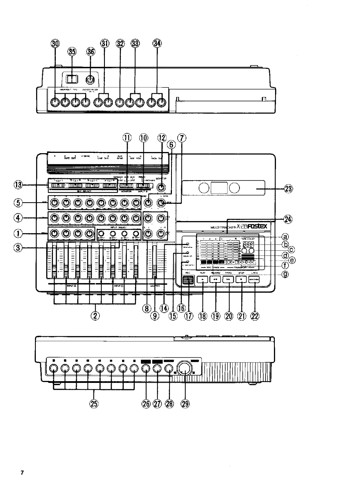
PANEL
CONTROLS
AND
TERMINALS
_
(Bold
words
in
parentheses
are
the
names
of
the
controls
as
they
appear
on
the
panel.)
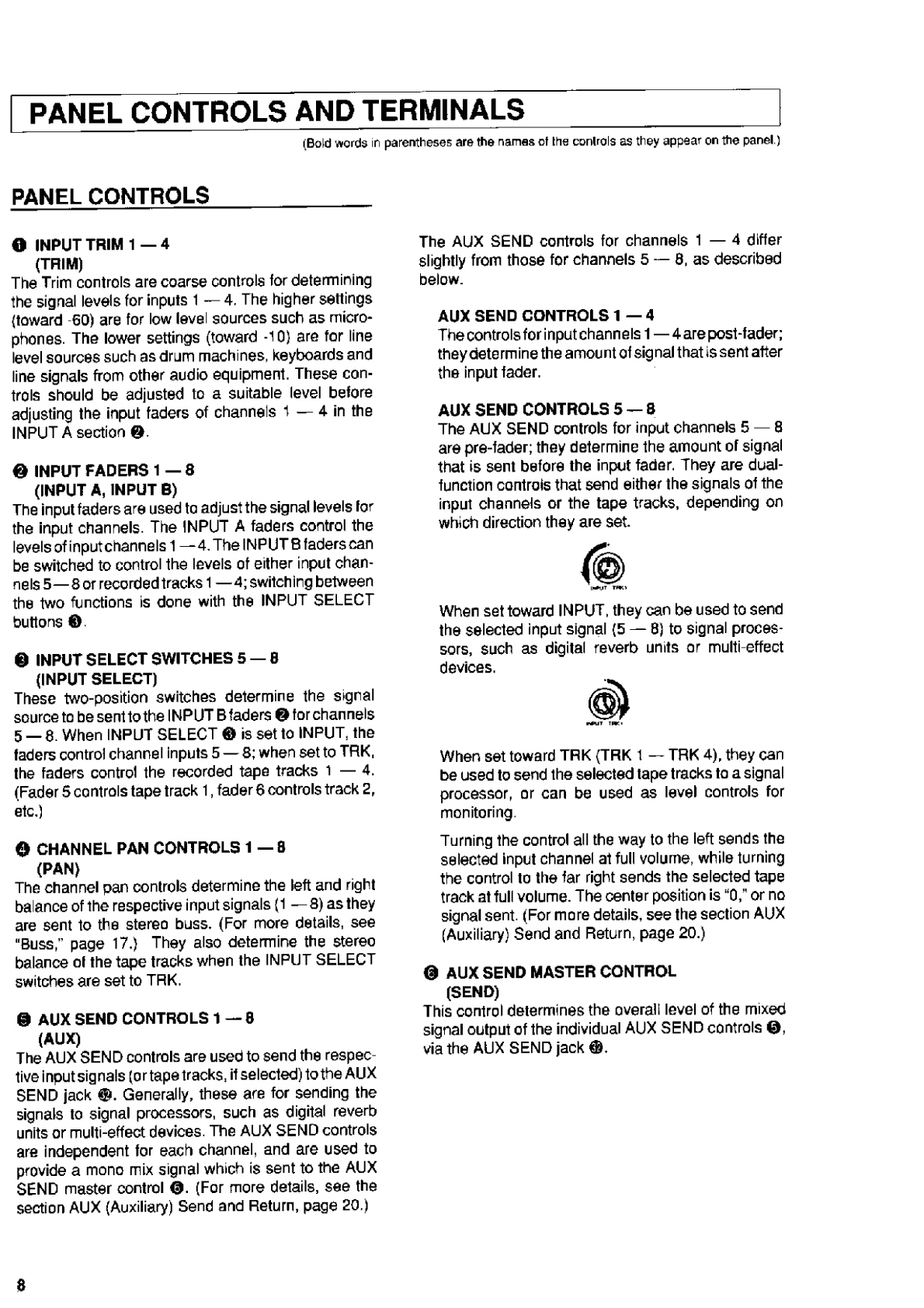
PANEL
CONTROLS
O
INPUT
TRIM
1
—4
(TRIM)
The
Trim
controls
are
coarse
controls
for
determining
the
signal
levels
for
inputs
1
—
4,
The
higher
settings
(toward
-60)
are
for
low
level
sources
such
as
micro¬
phones.
The
lower
settings
(toward
-10}
are
for
line
level
sources
such
as
drum
machines,
keyboards
and
line
signals
from
other
audio
equipment.
These
con¬
trols
should
be
adjusted
to
a
suitable
level
before
adjusting
the
input
faders
of
channels
1
—
4
in
the
INPUT
A
section
@.
©
INPUT
FADERS
1
—
8
(INPUT
A,
INPUT
B)
The
input
faders
are
used
to
adjust
the
signal
levels
for
the
input
channels.
The
INPUT
A
faders
control
the
levels
of
inputchannelsl
—4.
The
INPUT
B
faders
can
be
switched
to
control
the
levels
of
either
input
chan¬
nels
5—8or
recorded
tracks
1
—4;
switching
between
the
two
functions
is
done
with
the
INPUT
SELECT
buttons
©
©
INPUT
SELECT
SWITCHES
5
—8
(INPUT
SELECT)
These
two-position
switches
determine
the
signal
source
to
be
sent
to
the
INPUT
B
faders
©
for
channels
5_8.
When
INPUT
SELECT
©
is
set
to
INPUT,
the
faders
control
channel
inputs
5
—
8;
when
set
to
TRK,
the
faders
control
the
recorded
tape
tracks
1
—
4.
(Fader
5
controls
tape
track
1,
fader
6
controls
track
2,
etc.)
©
CHANNEL
PAN
CONTROLS
1
—
8
(PAN)
The
channel
pan
controls
determine
the
left
and
right
balance
of
the
respective
input
signals
(1
—
8)
as
they
are
sent
to
the
stereo
buss.
(For
more
details,
see
"Buss,”
page
17.)
They
also
determine
the
stereo
balance
of
the
tape
tracks
when
the
INPUT
SELECT
switches
are
set
to
TRK.
@
AUX
SEND
CONTROLS
1
—8
(AUX)
The
AUX
SEND
controls
are
used
to
send
the
respec¬
tive
input
signals
(or
tape
tracks,
if
selected)
to
the
AUX
SEND
jack
©.
Generally,
these
are
for
sending
the
signals
to
signal
processors,
such
as
digital
reverb
units
or
multi-effect
devices.
The
AUX
SEND
controls
are
independent
for
each
channel,
and
are
used
to
provide
a
mono
mix
signal
which
is
sent
to
the
AUX
SEND
master
control
©.
(For
more
details,
see
the
section
AUX
(Auxiliary)
Send
and
Return,
page
20.)
The
AUX
SEND
controls
for
channels
1
—
4
differ
slightly
from
those
for
channels
5
—
8,
as
described
below.
AUX
SEND
CONTROLS
1
—
4
The
controls
for
input
channels
1—4
are
post-fader;
they
determine
the
amount
of
signal
that
is
sent
after
the
input
fader.
AUX
SEND
CONTROLS
5
—
8
The
AUX
SEND
controls
for
input
channels
5
—
8
are
pre-fader;
they
determine
the
amount
of
signal
that
is
sent
before
the
input
fader.
They
are
dual¬
function
controls
that
send
either
the
signals
of
the
input
channels
or
the
tape
tracks,
depending
on
which
direction
they
are
set.
When
set
toward
INPUT,
they
can
be
used
to
send
the
selected
input
signal
(5
—
8)
to
signal
proces¬
sors,
such
as
digital
reverb
units
or
multi-effect
devices.
When
set
toward
TRK
(TRK
1
—
TRK
4),
they
can
be
used
to
send
the
selected
tape
tracks
to
a
signal
processor,
or
can
be
used
as
level
controls
for
monitoring.
Turning
the
control
all
the
way
to
the
left
sends
the
selected
input
channel
at
full
volume,
while
turning
the
control
to
the
far
right
sends
the
selected
tape
track
at
full
volume.
The
center
position
is
“0,"
or
no
signal
sent.
(For
more
details,
see
the
section
AUX
(Auxiliary)
Send
and
Return,
page
20.)
©
AUX
SEND
MASTER
CONTROL
(SEND)
This
control
determines
the
overall
level
of
the
mixed
signal
output
of
the
individual
AUX
SEND
controls
©,
via
the
AUX
SEND
jack
©.
8

Q
AUX
RETURN
CONTROL
(RTN)
The
AUX
RETURN
control
determines
the
level
of
the
signal
that
is
received
at
the
AUX
RETURNjacks®.This
is
normally
used
to
control
the
amount
of
effect
pro¬
cessing
(sent
via
AUX
SEND
©
and
©
that
is
"re¬
turned"
to
the
X-28.
AUX
SEND
I
Effect
device
TT
REMIX
This
position
sends
the
signal
to
the
stereo
buss.
Normally,
REMIX
is
used
in
most
recording
situa¬
tions,
including
recording
ol
input
signals
connected
to
channels
5
—
8,
ping-pong
recording
and
mixdown.
MONMIX
This
position
sends
the
signal
to
the
monitor
buss
(the
monitor
out
and
headphone
jacks).
Since
this
switch
comes
before
the
MONITOR
select
switch
in
the
signal
path,
the
MONITOR
select
switch
must
be
set
to
MON
MIX
+
LI
N
E
for
the
signal
to
be
heard.
©
MONITOR
SELECT
SWITCH
(MONITOR)
This
switch
determines
which
signals
are
sent
to
the
monitor
out
and
headphone
jacks.
The
switch
has
three
positions:
MONMIX
+
LINE,
AUX
and
AUX
+
LINE.
MONMIX
+
LINE
This
position
sends
a
mix
of
two
signals
to
the
monitor
buss:
1)
the
stereo
signal
of
the
INPUT
B
channels
(when
MONMIX
is
selected
with
the
IN¬
PUT
B
select
switch
©),
and
2}
the
signal
of
the
stereo
buss.
AUX
This
position
sends
a
mono
mix
of
the
AUX
SEND
signal
to
the
monitor
buss.
L
ft
AUX
RTN
RTN
AUX
to
stereo
buss
Ft
lo
stereo
busa
L
©
EQUALIZER
CONTROLS
(EQ
HI,
EQ
L0)
These
controls
provide
two-band
equalization
(high
and
low)
for
the
stereo
mix.
The
controls
co
me
after
the
input
faders
and
before
the
stereo
master
fader.
@
STEREO
MASTER
FADER
(MASTER)
This
ganged
slide
control
determines
the
overall
output
level
of
the
stereo
buss—the
signals
sent
to
the
LINE
OUT
jacks
®.
©
INPUT
B
SELECT
SWITCH
(INPUT
B)
This
switch
determines
whether
the
stereo
signal
from
the
INPUT
B
channels
is
sent
to
the
stereo
buss
or
to
the
monitor
buss.
The
switch
has
two
positions:
REMIX
and
MONMIX.
AUX
+
LINE
This
position
sends
a
mix
of
the
mono
AUX
SEND
signal
and
the
signal
of
the
stereo
buss.
The
following
chart
lists
the
settings
for
the
INPUT
B
and
MONITOR
switches
as
used
in
the
various
record¬
ing
operations
of
the
X-28.
Operation
INPUT
B
Switch
MONITOR
Switch
Recording
Recording
to
channels
1
-
4
only
MONMIX
AUX
(fixed
center
position},
or
MONMIX
+
LINE
(stereo
monitor-
ing)
Recording
lo
channels
5-8
REMIX
AUX
(or,
in
the
case
ol
stereo
recording:
MONMIX
+
LINE)
Overdubbing
Rehearsal
MONMIX
AUX
+
LINE
Take
(recording)
MONMIX
AUX
For
monitoring
recorder
output
in
stereo
MONMIX
MONMIX
+
LINE
Ping-pong
Recording
Rehearsal
REMIX
MONMIX
+
LINE
Take
(recording)
REMIX
AUX
Mixdown
For
sending
stereo
signal
via
LINE
OUT
jacks
lo
master
recorder
REMIX
MONMIX
+
LINE
_|
For
sending
stereo
signal
via
MON
OUT
jacks
to
master
recorder,
especially
in
tape
sync
applications
REMIX
l
AUX
+
LINE
9

©
MONITOR
LEVEL
CONTROL
(MONITOR)
Determines
the
overall
output
level
sent
to
the
MON
OUT
jacks
©
and
PHONES
jack
©.
©
RECORD
TRACK
SELECT
SWITCHES
(REC
SELECT)
These
three-position
switches
select
the
track(s)
to
be
recorded.
Setting
the
switch
to
the
numbered
position
(1,2,3
and
4)
selects
the
respective
tape
tracks;
these
are
direct
record
settings
that
bypass
the
PAN
and
EQ
controls.
Setting
the
switch
to
the
center
position
dis¬
ables
recording.
Setting
it
to
L
(left)
or
R
(right)
selects
the
respective
signal
of
the
stereo
buss
for
recording.
The
signal
is
recorded
to
the
track
number
indicated
on
the
switch.
(For
example,
if
the
first
REC
SELECT
switch
is
set
to
L,
the
left
signal
of
the
stereo
buss
will
be
recorded
to
track
1.)
This
setting
is
particularly
useful
for
recording
multiple
inputs
sent
on
the
stereo
buss
to
a
single
track.
©
REHEARSAL
SWITCH
(REHEARSAL)
This
switch
is
used
for
disabling/enabling
recording
during
punch-in
recording.
It
also
lets
you
hear
the
punch-in
and
punch-out
as
you
rehearse,
without
erasing
the
original
track.
Normally,
pressing
the
footswitch
automatically
acti¬
vates
punch-in/out
recording
and
could
result
in
the
inadvertent
erasing
of
a
track.
To
avoid
this,
the
RE¬
HEARS
ALswitch
provides
a
safety
function
that
allows
you
to
set
up
and
practice
a
punch-in
recording
before
actually
executing
it.
The
REHEARSAL
switch
effec¬
tively
simulates
the
actual
punch-in
recording
process
by
switching
the
monitor
between
the
original
track
and
the
part
to
be
punched-in,
each
time
the
footswitch
is
pressed.
(See
Punch-in
Recording,
page
21,
for
de¬
tails.)
©
NOISE
REDUCTION
SWITCH
(DOLBY
NR)
This
switch
turns
the
Dolby
B
noise
reduction
system
on
and
off.
For
best
sonic
results,
you
should
keep
this
switch
on.
The
off
position
is
for
performing
calibration
and
alignment
operations.
©
COUNTER
RESET
SWITCH
(COUNT
RESET)
Pressing
this
button
resets
the
tape
counter
©
-
b
to
“
0
0
0
.
"
©
RECORD
BUTTON
(REC)
Pressing
this
button
(after
the
REC
SELECT
switches
©
have
been
properly
set)
allows
you
to
monitor
the
level
of
the
input
with
the
bar
graph
level
meters
©
-
a.
(Pressing
the
REC
button
alone
does
not
actually
start
recording,
however.
To
record,
hold
down
the
REC
button
and
simultaneously
press
PLAY.
Note:
Recording
can
also
be
started.
During
play¬
back,
hold
down
the
REC
button
and
simulta¬
neously
press
PLAY;
if
the
REC
SELECT
switches
have
been
properly
set,
recording
will
start.
©
PLAY
BUTTON
(PLAY)
©
REWIND
BUTTON
(REWIND)
©
FAST
FORWARD
BUTTON
(F.
FWD)
©
STOP
BUTTON
(STOP)
@
ZERO
RETURN
BUTTON
(0
RTN)
Pressing
this
button
rewinds
or
fast
forwards
the
tape
to
the
“000”
position.
(The
zero
return
indicator
in
the
display
(
►
►
0
or
0-«)
will
light,)
This
function,
used
with
the
COUNT
RESET
switch
©,
makes
it
easy
to
“mark"
a
specific
point
in
the
recording
and
return
to
it
auto¬
matically.
Pressing
the
PLAY
button
after
pressing
the
ZERO
RETURN
button
activates
auto
play;
playback
auto¬
matically
begins
once
the
tape
transport
reaches
the
“000”
position.
(The
play
indicator
in
the
display
will
flash.)
The
PLAY
button
can
be
pressed
at
any
time
while
the
tape
is
being
rewound
or
fast
forwarded
to
activate
the
function.
©
DECK
TRANSPORT
©
DISPLAY
a:
BAR
GRAPH
LEVEL
METERS
These
six
meters
indicate
the
signal
levels
of
the
four
tape
tracks
and
the
stereo
buss.
b:
TAPE
COUNTER
(TAPE
COUNT)
This
indicates
the
current
position
of
the
tape,
c:
TAPE
INDICATOR
This
provides
visual
indication
of
whether
the
tape
is
stopped
or
not
and
what
direction
it
is
moving.
This
indicator
lights
when
a
cassette
tape
is
inserted.
10
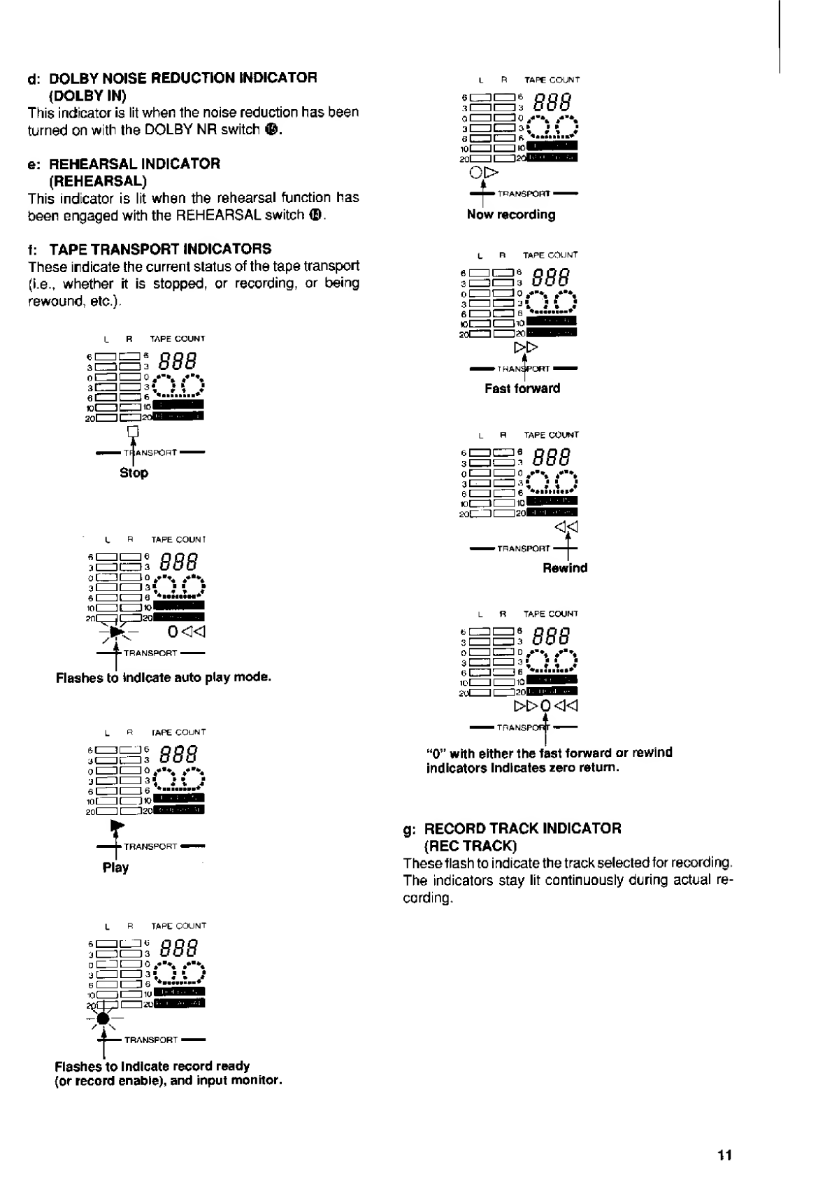
d:
DOLBY
NOISE
REDUCTION
INDICATOR
(DOLBY
IN)
This
indicator
is
lit
when
the
noise
reduction
has
been
turned
on
with
the
DOLBY
NR
switch
®.
e:
REHEARSAL
INDICATOR
(REHEARSAL)
This
indicator
is
lit
when
the
rehearsal
function
has
been
engaged
with
the
REHEARSAL
switch
®.
TAPE
COUNT
888
oi>
TRANSPORT!"
I
Now
recording
t:
TAPE
TRANSPORT
INDICATORS
These
indicate
the
current
status
of
the
tape
transport
(i.e.,
whether
it
is
stopped,
or
recording,
or
being
rewound,
etc.)
TAPE
COUNT
IANS
PORT
■
Stop
TAPE
COUN
T
I
888
o
L_U
[-
1
0
*+“**
■
i
i
ir
la*
■
■
■
6
I
1
[
1
Q
*
■
*
■
«•*
■
+
m
l
it
1
K>
B
?n
r^~jr
l
2ol
-1-TRANSPORT-
Flashes
to
Indicate
auto
play
mode.
TAPE
COUNT
888
TRANSPORT
<
Play
TAPE
COUNT
888
—
T
han^port
—
Fast
forward
L
H
TAPE
COUNT
elZZIC^s
QQQ
3
1
-
M
-)
a
OuO
o
1^^
o
/
■
%
ic=is;
;
e
cm
e
*.
mrnr
120
!
—
TRANSPORT
I
Rewind
TAPE
COUNT
ir
r
i^^n
oi
?n
l
11
\
2
0L
t»0«l
poiA
-
■
TRANSPC
“0”
with
either
the
fast
forward
or
rewind
indicators
Indicates
zero
return.
g:
RECORD
TRACK
INDICATOR
(REC
TRACK)
These
flash
to
indicate
the
track
selected
tor
recording.
The
indicators
stay
lit
continuously
during
actual
re¬
cording.
TAPE
COUNT
888
■
j
TRANSPORT-
Flashes
to
Indicate
record
ready
(or
record
enable),
and
input
monitor.
11

FRONT
PANEL
SECTION
©
INPUT
JACKS
1
—
8
(1-8)
These
standard
1/4”
phone
jacks
are
for
connecting
the
signal
inputs
to
be
recorded.
Inputs
1
—
4
are
equipped
with
trim
controls
O
and
can
be
used
with
virtually
any
kind
of
source,
including
microphones
and
electric
guitars.
Inputs
5—8
are
designed
for
use
only
with
line
level
instruments.
©
REMOTE
PUNCH
IN/OUT
JACK
(PUNCH
IN/OUT)
This
standard
1/4"
phone
jack
is
for
connecting
an
optional
footswitch
(Fostex
8051)
lor
remote
foot
co
nt
ro
I
of
punch-in/out
recording.
(See
the
section
Punch-in
Recording,
page
21.)
©
REMOTE
ZERO
RETURN/PLAY
JACK
(0
RTN/PLAY)
This
standard
1/4"
phone
jack
is
for
connecting
an
optional
footswitch
(Fostex
8051)
for
remote
control
of
the
zero
return
function.
Pressing
the
footswitch
auto¬
matically
returns
the
tape
to
the
"000”
position
and
starts
playback.
©
HEADPHONE
JACK
(PHONES)
This
standard
1/4"
phone
jack
is
forconnecting
a
set
of
stereo
headphones.
©
PITCH
CONTROL
(PITCH)
The
pitch
control
lets
you
finely
adjust
the
pitch
(or
speed)
of
playback
within
a
range
of
±
10%.
REAR
PANEL
SECTION
©
TAPE
OUT
JACKS
1
—
4/SYNC
(TAPE
OUT
1
—
4/SYNC)
The
signals
of
the
four
recorded
tracks
are
output
via
these
standard
RCA
pinjacks.
These
are
used
to
send
the
individual
outputs
to
an
external
mixer
for
greater
flexibility
in
monitoring,
or
for
putting
different
effects
on
each
of
the
tracks.
©
LINE
OUT
JACKS
LEFT,
RIGHT
(LINE
OUT
L,
R)
The
signals
of
the
stereo
buss
are
output
via
these
standard
RCA
pin
jacks.
These
are
used
to
send
the
stereo
output
to
a
second
tape
recorder
for
making
a
stereo
master
tape.
©
AUX
SEND
JACK
(AUX
SEND)
The
mixed
signals
of
AUX
SEND
©
and
©
are
output
via
this
standard
RCA
pinjack.
A
signal
processorsuch
as
a
reverb
unit
or
multi-effect
device
may
be
con¬
nected
here.
©
AUX
RETURN
JACKS
LEFT,
RIGHT
(AUX
RTN
L,
R)
These
standard
RCA
pin
jacks
are
inputs
for
the
“returning"
effects-processed
AUX
SEND
signal;
the
signal
is
then
sent
to
the
stereo
buss.
Two
jacks
are
provided,
since
many
effect
devices
have
stereo
out¬
puts.
The
jacks
can
also
be
used
as
auxiliary
inputs,
effectively
giving
the
X-28
ten
inputs.
©
MONITOR
OUT
JACKS
LEFT,
RIGHT
(MON
OUT
L,
R)
The
signals
selected
with
the
MONITOR
select
switch
(the
same
as
those
heard
in
the
headphones)
is
output
via
these
standard
RCA
pin
jacks.
These
jacks
are
for
connecting
to
an
amplifier/speaker
system
for
moni¬
toring.
©
POWER
SWITCH
(STANDBY/OFF)
(The
STANDBY
position
is
equivalent
to
“ON.")
©
AC
ADAPTER
CONNECTOR
(DC
IN~12V)
For
connecting
to
the
included
AC
adapter.
12
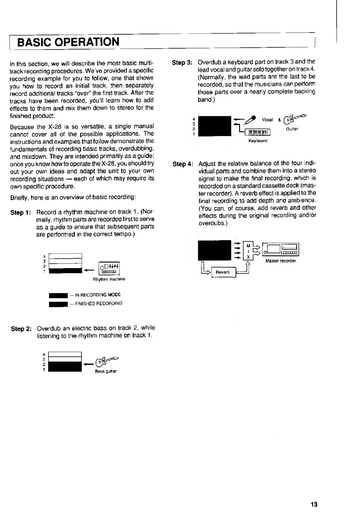
BASIC
OPERATION
In
this
section,
we
will
describe
the
most
basic
multi¬
track
recording
procedures.
We've
provided
a
specific
recording
example
for
you
to
follow,
one
that
shows
you
how
to
record
an
initial
track,
then
separately
record
additional
tracks
"over"
the
first
track.
After
the
tracks
have
been
recorded,
you’ll
learn
how
to
add
effects
to
them
and
mix
them
down
to
stereo
for
the
finished
product.
Because
the
X-28
is
so
versatile,
a
single
manual
cannot
cover
all
of
the
possible
applications.
The
instructions
and
examples
that
follow
demonstrate
the
fundamentals
of
recording
basic
tracks,
overdubbing,
and
mixdown.
They
are
intended
primarily
as
a
guide;
once
you
know
howto
operate
the
X-28,
you
should
try
out
your
own
ideas
and
adapt
the
unit
to
your
own
recording
situations
—
each
of
which
may
require
its
own
specific
procedure.
Briefly,
here
is
an
overview
of
basic
recording:
Step
1:
Record
a
rhythm
machine
on
track
1.
(Nor¬
mally,
rhythm
parts
are
recorded
first
to
serve
as
a
guide
to
ensure
that
subsequent
parts
are
performed
in
the
correct
tempo.)
4
3
2
1
oDW+*
aatrano
Rhythm
machine
-IN
RECORDING
MODE
I
—
FINISHED
RECORDING
Step
3:
Overdub
a
keyboard
part
on
track
3
and
the
lead
vocal
and
gu
itar
solo
together
on
track
4.
(Normally,
the
lead
parts
are
the
last
to
be
recorded,
so
that
the
musicians
can
perform
those
parts
over
a
nearly
complete
backing
band.)
4
3
2
1
*u
Vocal
Onm
Keyboard
&
Guitar
Step
4:
Adjust
the
relative
balance
of
the
four
indi¬
vidual
parts
and
combine
them
into
a
stereo
signal
to
make
the
final
recording,
which
is
recorded
on
a
standard
cassette
deck
(mas¬
ter
recorder).
A
reverb
effect
is
applied
to
the
final
recording
to
add
depth
and
ambience.
(You
can,
of
course,
add
reverb
and
other
effects
during
the
original
recording
and/or
overdubs.)
Master
recorder
Step
2:
Overdub
an
electric
bass
on
track
2,
while
listening
to
the
rhythm
machine
on
track
1,
4
3
2
1
Bass
guitar
13

Recording
the
First
Track
—
Rhythm
Machine
1.
First,
make
sure
that
all
controls
on
the
X-28
are
at
their
minimum
or
OFF
settings.
Most
importantly,
this
means
that
all
faders
should
be
down,
the
MONITOR
control
should
be
at
0,
the
REC
SE¬
LECT
switches
should
be
at
the
center
(OFF)
position,
and
the
TRIM
controls
should
be
set
to
-10.
Also,
make
sure
that
the
MONITOR
select
switch
is
setto
one
of
the
“LINE”
settings
(MONMIX
+
LINE
or
AUX
+
LINE).
2.
Make
the
necessary
connections
for
listening
to,
or
“monitoring"
your
recording.
Hyou
are
using
a
set
of
stereo
headphones,
plug
them
into
the
PHONES
jack.
If
you
are
using
an
amplifier/speaker
system,
connect
it
to
the
MON
OUT
jacks
on
the
X-28.
Headphone
monitoring
is
convenient,
and
some¬
times
even
necessary
—
when
recording
vocals
and
acoustic
instruments
—
in
orderto
avoid
feed¬
back
from
microphones.
However,
a
good
ampli¬
fier/speaker
system
provides
the
best
and
most
accurate
listening
source
and
should
be
used
whenever
possible.
3.
Plug
the
output
of
the
rhythm
machine
into
the
INPUT
1
jack.
4.
S
witch
the
leftmost
REC
SELECT
switch
to
1
and
press
the
REC
button.
In
the
display,
the
number
1
REC
TRACK
indicator
and
the
REC
indicator
flash
together,
indicating
that
track
1
is
set
up
for
record¬
ing
and
that
the
signal
can
be
monitored
on
the
level
meter
for
track
1.
Q
QipL
2-iirB
J-lil-l-
Press
REC
button.
14

REC
SELECT
SWITCH
AND
DIRECT-
RECORDING:
Setting
the
REC
SELECT
switches
to
the
numbered
positions
(1,2,
3
and
4)
enables
direct
recording.
This
means
that
the
signal
on
the
selected
input
channel
is
recorded
directly
to
the
corresponding
track,
bypassing
the
PAN
and
AUX
SEND
controls
of
the
channel,
as
well
as
the
EQ
controls
and
MASTER
fader.
The
REC
SELECT
switch
must
be
set
to
the
same
number
as
the
channel
to
which
the
input
signal
is
connected.
(For
example,
if
the
signal
is
connected
to
channel
1,
the
leftmost
REC
SE¬
LECT
switch
must
be
set
to
1.)
5.
N
ow,
adjust
the
level
of
the
input
signal.
Bring
the
MASTER
fader
up
to
around
7.
Do
the
same
with
the
INPUT
1
fader,
This
is
the
optimum
position
of
the
faders.
(The
word
"optimum"
does
not
mean
“maximum,”
but
indicates
the
“best”
position
—
in
this
case,
the
highest
level
with
the
least
distortion.)
1_
g
3
4
5
6
_
master
6.
S
tart
the
rhythm
machine
and
increase
its
volume
control
slowly
to
an
optimum
level.
Gradually
in¬
crease
the
TRIM
control
(toward
the
-60
position)
so
that
the
meter
indication
fortrack
1
in
the
display
peaks
around
0
or
+3.
Make
sure
that
the
loudest
signals
do
not
consistently
push
the
meter
into
the
+3
to
+6
range,
(if
you
are
recording
something
other
than
a
rhythm
machine
to
this
track,
such
as
a
vocal
or
an
acoustic
instrument,
the
TRIM
control
may
need
to
be
set
near
the
-60
position.)
Gradually
Increase
TRIM
Meter
should
peak
around
0
~
+3
At
this
stage,
you
are
setting
levels
so
you
needn't
worry
about
content.
If
your
level
readings
are
con¬
stantly
in
the
-10
to
-
20
range,
increase
the
level
by
bringing
up
the
faders
or
there
will
be
excessive
back¬
ground
noise.
If
your
level
readings
are
constantly
in
the
+3
to
+6
range,
bring
the
level
down
or
there
will
be
distortion.
When
recording
instruments
with
very
sharp
initial
attacks
such
as
bass
and
snare
drums,
you
may
find
it
necessary
to
set
the
levels
at
a
relatively
low
range
—
for
example,
around
-6
to
-10
—
just
to
keep
the
signal
from
distorting.
A
compressor
such
as
the
Fostex
MN-50
will
help
solve
this
problem,
Note:
The
left
and/or
right
meters
of
the
stereo
buss
will
tight
to
indicate
the
level
of
the
signal.
Whether
one
or
both
of
the
meters
lights
de¬
pends
on
the
setting
of
the
PAN
control
on
the
input
track;
for
example,
if
the
PAN
control
is
set
to
the
left,
the
left
meter
will
be
active.
The
PAN
setting
here
does
not
affect
the
recording.
How¬
ever,
for
monitoring
purposes,
it
is
best
to
set
this
at
the
center
position.
7.
N
ext,
make
the
necessary
settings
on
the
X-28
for
monitoring.
Whether
you
are
using
headphones
or
an
amptifier/speaker
system,
simply
turn
the
MONI¬
TOR
control
up
to
around
5,
or
to
a
comfortable
listening
level.
Note
that
you
may
also
have
to
make
adjustments
on
all
of
the
level
controls
in
the
re¬
cording
and
monitor
circuits
it
the
volume
is
too
loud
or
soft.
Note:
Since
this
first
recording
(basic
track)
will
be
used
as
a
reference
for
all
additional
recordings,
it's
a
good
idea
to
begin
with
a
rhythmic
count¬
off
with
the
snare
drum
before
the
actual
downbeat
or
upbeat
of
the
performance
begins.
(This
makes
overdubbing
a
lot
easier.)
Note:
Make
sure
that
the
noise
reduction
(DOLBY
NR)
switch
has
been
turned
on
—
both
for
recording
and
playback.
This
will
make
your
recording
sound
as
clean
and
clear
as
possible.
15

^Monitoring-
Understanding
the
concept
ol
monitoring
is
essen¬
tia!
to
mastering
the
multitrack
record
process.
To
monitor
a
recording
means
to
listen
to
it.
It
also
means
to
check
sound
levels
—
aurally,
over
the
headphones
or
speaker
system,
or
visually,
by
means
of
the
level
meters.
One
important
thing
you
should
understand
about
monitoring
is
that
you
can
be
recording
a
signal
at
one
level
and
yet
be
hearing
it
through
the
monitor
at
a
different
level.
This
is
particularly
crucial,
for
example,
if
the
MONITOR
control
is
set
nearO.
You
may
find
yourself
cranking
up
the
input
faders
and
TRIM
controls
just
to
be
able
to
hear
the
signal
—
which
could
result
in
a
horribly
distorted
recording,
and
even
possible
damage
to
the
recorder.
For
this
reason,
always
set
the
monitor
controls
to
their
optimum
positions
first,
then
adjust
the
input
levels.
Another
thing
to
remember
is
that
there
are
two
different
types
of
signals
that
are
monitored
during
the
recording
process:
those
currently
being
re¬
corded
(live
or
input
signals)
and
those
that
have
already
been
recorded
(tape
signals).
This
differ¬
ence
is
important
in
overdubbing.
You
must
adjust
the
levels
of
the
individual
tape
signals
with
the
faders
to
get
the
proper
balance
of
the
recorded
tracks
when
overdubbing
a
new
part.
The
X-28
always
gives
you
a
visual
monitor
of
the
tape
signals
with
the
level
meters
in
the
display,
regardless
of
the
monitor
settings.
However,
with
direct
recording
(setting
REC
SELECT
to
track
numbers),
the
input
bypasses
the
stereo
buss,
and
the
level
shown
in
the
stereo
buss
meter
is
NOT
a
true
indication
of
the
level
that
is
to
be
recorded
to
the
track.
Always
be
sure
to
press
the
REC
button
to
enable
input
monitoring
with
the
REC
TRACK
level
meters.
For
more
information
on
monitoring,
see
the
boxed
section,
AUX
(Auxiliary)
Send
and
Return,
page
20.
8.
Now
you’re
ready
to
record.
Press
the
PLAY
and
the
REC
button
simultaneously.
(The
REC
TRACK
indicator
for
track
1
will
be
lit
continuously,
as
will
the
record
and
play
TRANSPORT
indicators.)
tape
SQlMI
i
-
FEC
TRACK
-
-TRANSPORT-
FLAT
REYVHO
P
F
WO
3
T
O
p
i~“ii
--
imhH
i
Press
these
buttons
simultaneously.
These
indicartors
will
be
lit
continuously.
|
WifT
*lECT
<.
l
G
n
A
.
0
O
a
©
^
Press
to
select
Increase
fader
5.
TRK
1,
9.
After
stopping
the
recording,
you’ll
want
to
listen
to
it
and
check
that
everything
has
been
recorded
satisfactorily.
First,
switch
the
leftmost
REC
SE¬
LECT
switch
back
to
the
center
position
to
disable
recording.
Then,
press
the
INPUT
SELECT
switch
of
INPUT
B
channel
5
to
select
TRK
1
and
bring
up
fader
5
to
a
suitable
level
(around
7).
Doing
this
selects
tape
track
1
for
playback.
Set
the
PAN
control
to
the
center
position,
for
optimum
monitor¬
ing.
Alsomakesure
that
the
MONITOR
switch
is
set
to
MONMIX
+
LINE,
and
INPUT
Bis
set
to
MONMIX.
Listen
to
your
newly
recorded
track
carefully.
If
there
is
too
much
hiss
or
noise,
the
recording
level
might
have
been
too
low.
If
there
is
too
much
distortion,
the
recording
level
might
have
been
too
high.
Record
the
track
again,
readjusting
thesettings
as
necessary
to
get
the
sound
you
want.
FOUR-TRACK
SIMULTANEOUS
RECORDING:
The
direct
recording
method,
used
to
record
the
rhythm
machine
in
the
above
example,
can
also
be
used
to
record
four
instruments
at
the
same
time
to
different
tracks.
To
do
this:
simply
follow
the
above
steps,
setting
up
tracks
2,3
and
4
for
recording
just
as
you
did
for
track
1.
If,
for
example,
you
are
recording
a
four-
piece
band,
record
each
of
the
musicians
on
a
separate
track,
and
set
the
levels
appropriately
before
record¬
ing.
Once
you
have
recorded
the
performance,
follow
the
instructions
for
mixdown
in
the
section
Mixdown
and
Effects
Processing
—
Adding
Reverb,
page
19.
16
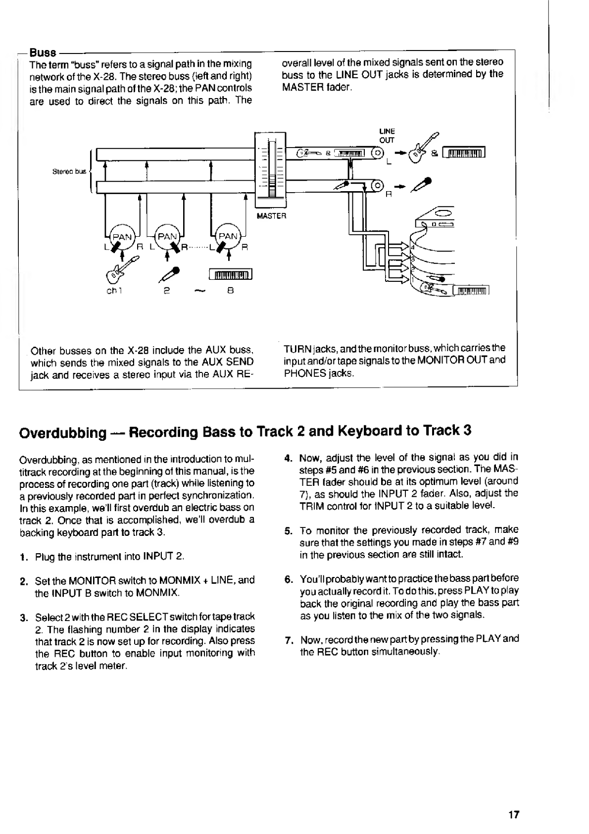
Buss-----
The
term
“buss”
refers
to
a
signal
path
in
the
mixing
network
of
the
X-28.
The
stereo
buss
{left
and
right)
is
the
main
signal
path
of
the
X-28;
the
PAN
controls
are
used
to
direct
the
signals
on
this
path.
The
overall
level
of
the
mixed
signals
sent
on
the
stereo
buss
to
the
LINE
OUT
jacks
is
determined
by
the
MASTER
fader.
Other
busses
on
the
X-28
include
the
AUX
buss,
which
sends
the
mixed
signals
to
the
AUX
SEND
jack
and
receives
a
stereo
input
via
the
AUX
RE¬
TURN
jacks,
and
the
monitor
buss,
which
carries
the
input
and/ortape
signals
to
the
MONITOR
OUT
and
PHONES
jacks.
—
Recording
Bass
to
Track
2
and
Keyboard
to
Track
3
Overdubbing
Overdubbing,
as
mentioned
in
the
introduction
to
mul¬
titrack
recording
at
the
beginning
ot
this
manual,
is
the
process
of
recording
one
part
(track)
while
listening
to
a
previously
recorded
part
in
perfect
synchronization.
In
this
example,
we
ll
first
overdub
an
electric
bass
on
track
2.
Once
that
is
accomplished,
we’ll
overdub
a
backing
keyboard
part
to
track
3.
1.
Plug
the
instrument
into
INPUT
2.
2.
Set
the
MONITOR
switch
to
MONMIX
+
LINE,
and
the
INPUT
B
switch
to
MONMIX.
3.
Select
2
with
the
REG
SELECT
switch
for
tape
track
2.
The
flashing
number
2
in
the
display
indicates
that
track
2
is
now
set
up
for
recording.
Also
press
the
REC
button
to
enable
input
monitoring
with
track
2's
level
meter.
4.
Now,
adjust
the
level
of
the
signal
as
you
did
in
steps
#5
and
#6
in
the
previous
section.
The
MAS¬
TER
fader
should
be
at
its
optimum
level
(around
7),
as
should
the
INPUT
2
fader.
Also,
adjust
the
TRIM
control
for
INPUT
2
to
a
suitable
level.
5.
To
monitor
the
previously
recorded
track,
make
sure
that
the
settings
you
made
in
steps
#7
and
#9
in
the
previous
section
are
still
intact.
6.
You'll
probably
want
to
practice
the
bass
part
before
you
actually
record
it.
To
do
this,
press
PLAY
to
play
back
the
original
recording
and
play
the
bass
part
as
you
listen
to
the
mix
of
the
two
signals.
7.
Now,
record
the
new
partby
pressing
the
PLAY
and
the
REC
button
simultaneously.
17

8.
To
hear
playback
of
the
two
tracks
together,
switch
the
REC
SELECT
switch
of
track
2
back
to
the
center
(off)
position,
then
switch
the
INPUT
SE¬
LECT
button
of
INPUT
B
channel
6
to
TRK
2
and
bring
up
fader
6
to
a
suitable
level.
Check
the
recording
by
listening
to
it
through
monitor
speak-
@
@
H
®
@
®
@
©
■
ers.
Use
the
faders
on
the
corresponding
INPUT
B
channels
(faders
5
and
6)
to
adjust
the
relative
balance
of
the
two
tracks.
9.
Overdub
the
backing
keyboard
parts
on
track
3,
following
the
same
procedure
given
above,
using
INPUT
3
this
time.
&
Press
to
select
TRK
2.
Vocal
and
Guitar
Overdubbing
the
Final
Track
—
Now
that
you
have
recorded
the
basic
parts
of
a
backing
band
(drums,
bass
and
keyboards)
to
on
the
first
three
tape
tracks,
you
can
use
track
4
to
record
the
lead
parts
of
the
song
—
the
vocals
and
a
guitar
solo.
1.
In
this
example,
since
you
will
be
recording
two
parts
at
one
time,
you’ll
need
to
use
two
input
channels.
Connect
the
vocal
microphone
to
INPUT
1
and
the
guitar
to
INPUT
2.
2.
Since
these
inputs
will
be
recorded
on
a
single
track,
you
must
use
the
stereo
buss
instead
of
the
direct
recording
function.
To
do
this,
set
track
4’s
REC
SELECT
switch
to
R.
Also
make
sure
the
PAN
controls
of
channels
f
and
2
are
set
all
the
way
to
R.
This
directs
both
input
signals
to
the
right
side
of
the
stereo
buss
and
records
them
on
track
4.
3.
Make
sure
to
use
headphones
for
monitoring,
to
avoid
feedback
when
recording
the
vocal
part,
The
signal
will
be
coming
from
the
right
side
of
your
headphones,
so
you
may
want
to
monitorthe
signal
from
the
center
ofthe
stereo
image.
Todothis,
refer
to
the
box,
MONO
MONITORING
IN
STEREO
RECORDING,
below.
Note:
The
following
instructions
(step#4,
in
particular)
assume
that
you
are
using
this
technique
of
monitoring
the
signal
from
the
center.
Even
if
you
don't,
though,
they
will
still
be
relevant
to
the
recording
of
your
vocal
and
guitar
parts.
4.
Make
sure
that
the
MONITOR
switch
is
set
to
AUX
+
LINE,
and
that
the
INPUT
B
switch
is
set
to
REMIX.
(Keep
them
at
these
settings
throughout
this
section.)
i-
MONO
MONITORING
IN
STEREO
RECORDING:
When
reoording
signals
over
the
stereo
buss
(set¬
ting
REC
SELECT
switches
to
L
or
R),
the
PAN
controls
for
the
relevant
channels
must
be
set
to
the
appropriate
side
of
the
stereo
buss.
This
means,
for
example,
that
if
you
are
recording
to
the
right
side
of
the
stereo
buss,
you
will
hear
the
signals
coming
from
only
the
right
side
ofthe
monitor.
This
is
fine
as
far
as
the
recording
is
concerned,
but
it
can
be
irritating
to
listen
to
—
especially
if
you
are
using
a
set
of
headphones.
You
can
eliminate
this
by
send¬
ing
the
monitor
signal
over
the
AUX
buss.
The
AUX
signal
isamix
that
is
sent
in
monotoboththe
left
and
right
channels
of
the
monitor.
To
do
this:
1.
Set
the
MONITOR
select
switch
to
AUX
(or
AUX
+
LINE),
and
make
sure
the
INPUT
B
switch
is
set
to
REMIX.
2.
Turn
up
the
AUX
SEND
controls
on
the
appropri¬
ate
channels.
(For
INPUT
B
channels,
they
should
be
set
most
or
all
the
way
clockwise
to
their
TRK
settings.)
Also
make
sure
that
the
master
AUX
SEND
control
0
is
set
to
a
suitable
level.
3.
With
the
MON
I
TOR
control
at
a
suitable
level,
you
can
now
hear
the
recorded
tracks
from
both
the
left
and
right
channels
of
your
headphones
or
speaker
system,
even
though
the
signal
is
being
recorded
over
just
one
side
of
the
stereo
buss.
18

5.
Press
the
REC
button
to
enable
input
monitoring
with
track
4’s
level
meter,
and
adjust
the
levels
of
the
signals.
The
MASTER
fader
should
be
at
its
optimum
level
(around
7),
as
should
the
INPUT
1
and
2
faders.
Also
adjust
the
TRIM
controls
for
the
inputs
to
suitable
levels.
6.
Monitor
the
previously
recorded
tracks.
Make
sure
that
the
INPUT
SELECT
switches
of
the
three
recorded
tracks
are
set
to
TRK.
Set
the
faders
for
the
channels
to
suitable
levels.
1
a
3
4
5
6
7
B
7.
P
ractice
the
vocal
and
guitar
parts
before
record¬
ing,
checking
the
level
of
the
signals
with
the
level
meters.
Press
the
REC
and
PLAY
buttons
simulta¬
neously
and
record
the
track
as
usual.
Mixdown
and
Effects
Processing
—
Adding
Reverb
Mixdown
is
the
process
of
playing
several
previously
Note:
This
example
assumes
that
you
have
a
reverb
recordedtracks(uptotour,irthecaseoftheX-28)and
unit,
preferably
one
with
stereo
outputs,
and
a
mixing
them
into
a
composite
signal
(stereo,
in
this
master
recording
deck
(cassette,
reel
to
reel,
or
case).
It
involves
adjusting
the
balance
of
the
individual
DAT).
tracks
in
terms
of
level
(gain),
stereo
placement
(pan),
and
depth
(reverb).
The
resulting
signal—the
finished
recording
—
is
normally
in
stereo,
and
is
copied
to
a
master
recorder,
usually
a
stereo
cassette
deck.
19
Other manuals for X-28
1
Table of contents
Other Fostex Recording Equipment manuals

Fostex
Fostex VF-16 User manual

Fostex
Fostex DV-824 User manual

Fostex
Fostex MTC1 User manual

Fostex
Fostex A-4 User manual

Fostex
Fostex A-2 User manual

Fostex
Fostex VF-16 User manual

Fostex
Fostex FR-2 Technical manual

Fostex
Fostex CR200 User manual

Fostex
Fostex DMT-8VL User manual

Fostex
Fostex XR-3 User manual

Fostex
Fostex 8345 User manual

Fostex
Fostex RD-8 User manual

Fostex
Fostex DV-824 Configuration guide

Fostex
Fostex DV-824 Configuration guide

Fostex
Fostex X-30 User manual

Fostex
Fostex VF80EX User manual

Fostex
Fostex D-10 User manual

Fostex
Fostex DV-824 User manual

Fostex
Fostex D-90 User manual

Fostex
Fostex VF-08 User manual


