7
Positionin the water softener
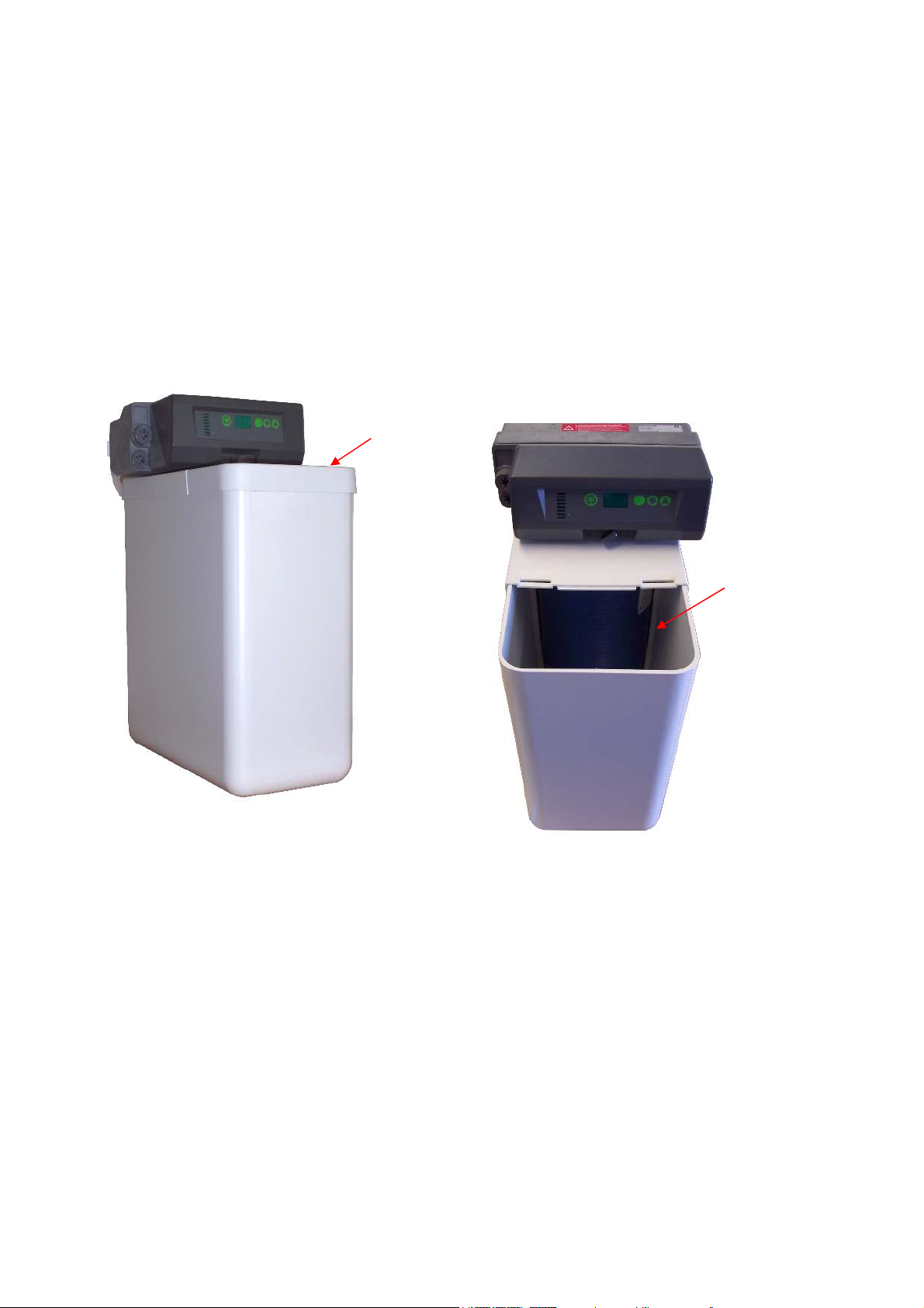
• Measure your water softener and the space where it will be installed. Remember to
allow extra space for connectin pipe work when you do your calculations and access
for future servicin and toppin up salt.
• Keep the distance of the incomin main and draina e to a minimum.
• The wei ht of the water softener is reatly increased when fully operational and filled
with salt so this needs to be taken into account when choosin where to site the
softener.
• Your softener is desi ned to operate effectively with an incomin water pressure of
between 1.5 and 6 bar. If your water supply is likely to fall outside these parameters we
recommend that a booster pump or pressure reducin valve should be fitted
accordin ly.
• Do not install your water softener next to a boiler or other heat source where the
ambient temperature will exceed 40’ C
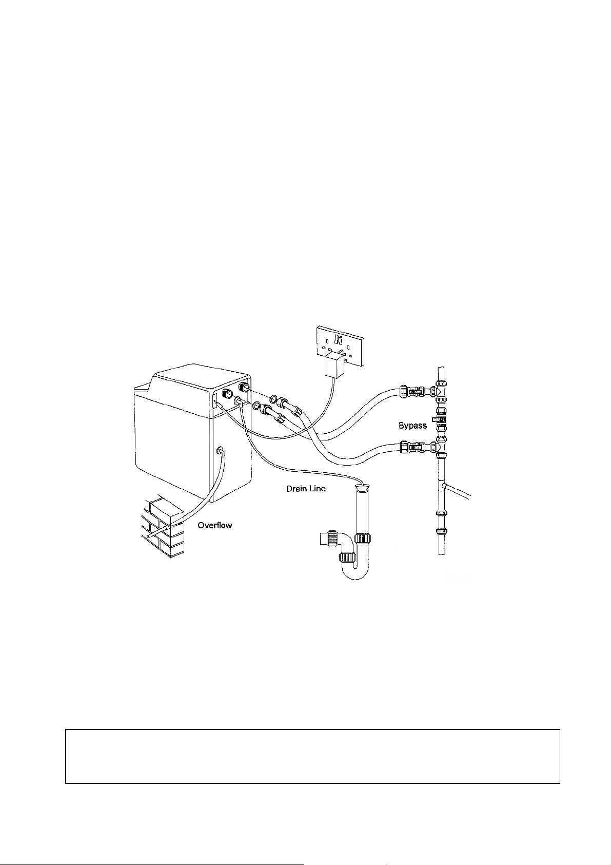
Bypass Connections
.
• A bypass loop should be installed on all softeners. The bypass valve isolates the Water
Softener from the water system and provides un-softened water to the water system
durin routine maintenance and servicin procedures. See fi ure 3..
Loft installation.
• The water softener may be installed in a loft or roof cavity but must be situated within a
safety bund tank of not less than 100 litre capacity. This tank should also be mounted
on a board stron enou h to spread the wei ht over a load bearin wall.
Drain Line Connection
.
• The unit should be above and not more than 6 meters from the drain. Use an
appropriate adapter fittin to connect 1.3cm plastic tubin to the drain line connection
of the control valve.
• The drain line may be elevated up to 1.8 meters providin the run does not exceed 4.6
meters and the water pressure at the softener is not less than 2.76 bar. Elevation can
increase by 61cm for each additional 0.69 bar of water pressure at the drain connector.
• Where the drain line is elevated but empties into a drain below the level of the control
valve, form an 18cm loop at the far end of the line so that the bottom of the loop is level
with the drain line connection. This will provide an adequate siphon tap.
• Where the drain empties into an overhead sewer line, a sin -type trap must be used.
• Secure the end of the drain line to prevent it from movin .
Safety Devices
A Backflow Prevention Device is required which has an air ap of 20 mm minimum on both
the independent re enerant drain and the brine tank overflow. The device needs to be in
accordance with EN 1717. The backflow prevention device is required to protect public water
from contamination.