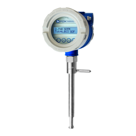
Fox Thermal FT1 User manual

831.384.4300 | 399 Reservation Rd, Marina, CA 93933 | foxthermal.com
MODEL
Instruction Manual
Document #106012
Rev L
Fox Thermal Gas Mass Flow Meter
FT1

| 2

Fox Thermal FT1 Manuals:
• Fox Thermal FT1 View™ Manual
All Fox Thermal Manuals and software available in English only.
Model FT1
Disclaimer
| 3
This publication must be read in its entirety before performing any operation. Failure to
understand and follow these instructions could result in serious personal injury and/or
damage to the equipment. Should this equipment require repair or adjustment beyond
the procedures given herein, contact the factory at:
FOX THERMAL INSTRUMENTS, INC.
399 RESERVATION ROAD
MARINA, CA 93933
TELEPHONE: 831-384-4300
EMAIL: SERVICE@FOXTHERMAL.COM
Download Technical Data Sheets from our website:
www.foxthermal.com
Fox Thermal Instruments, Inc. (Fox Thermal) believes that the information
provided herein is accurate; however, be advised that the information contained
herein is NOT a guarantee for satisfactory results. Specically, this information is
neither a warranty nor guarantee, expressed or implied, regarding performance,
merchantability, tness, or any other matter with respect to the products; nor
recommendation for the use of the product/process information in conict with
any patent. Please note that Fox Thermal reserves the right to change and/or
improve the product design and specication without notice.

| 4
Model FT1
Table of Contents
1. Introduction p. 6-18
a. Quick Start Guide .........................................................................p. 6
b. Menu Trees ..............................................................................p. 8
c. General ................................................................................p. 16
2. Installation (Mechanical) p. 19-30
a. Lateral Placement ........................................................................p. 20
b. Welding Branch Outlet to Pipe (Insertion)...................................................p. 22
c. Installation Depth ........................................................................p. 23
d. Orientation .............................................................................p. 24
e. Mounting Instructions ....................................................................p. 26
f. Retractor Installation......................................................................p. 28
3. Wiring (Electrical) p. 32-42
a. Wiring Access ...........................................................................p. 32
b. Input Power.............................................................................p. 34
c. 4-20mA Output Wiring ...................................................................p. 35
d. Pulse/Alarm Wiring (optional feature) ......................................................p. 37
e. RS485 Wiring: Modbus RTU or BACnet MS/TP (optional feature)...............................p. 39
f. HART Wiring.............................................................................p. 40
4. Operation (Standard Operation) p. 43-67
a. Start Up ................................................................................p. 43
b. Programming ...........................................................................p. 45
c. CAL-V™.................................................................................p. 61
d. Gas-SelectX® . . . . . . . . . . . . . . . . . . . . . . . . . . . . . . . . . . . . . . . . . . . . . . . . . . . . . . . . . . . . . . . . . . . . . . . . . . . p. 64
5. Communication Protocols p. 68-86
a. Modbus RTU (RS485).....................................................................p. 68
b. BACnet MS/TP (RS485) . . . . . . . . . . . . . . . . . . . . . . . . . . . . . . . . . . . . . . . . . . . . . . . . . . . . . . . . . . . . . . . . . . . p. 79
c. HART ...................................................................................p. 82

| 5
Model FT1
Table of Contents
6. Maintenance p. 87-97
a. Safe Meter Removal from Retractor ........................................................p. 89
b. Troubleshooting .........................................................................p. 93
7. Appendices p. 98-107
...........................................................................p. 98
b. Agency Approvals ......................................................................p. 101
c. Dimensions ............................................................................p. 102
d. Warranty ..............................................................................p. 106
e. Returning your meter ...................................................................p. 107
9. Index p. 109

1. Record inside diameter (ID). Ensure the actual pipe ID
matches the pipe ID shown on the factory calibration
2.
Record up/downstream straight-pipe requirements
based on Pipe ID and meter style (insertion or inline).
[refer to p. 20]
3. The Flow Direction Indicator must point in the
The housing can be rotated for a better view of the
meter's display. Note that the 2 set screws must be
loosened before the housing will turn. [refer to p.
24]
4.
pipe, please see note on p. 23.
5. Open the housing. If needed, the orientation of
display can be rotated in 90° increments for a better
view.
[refer to p. 25 for more information]
6. Ensure power wiring and output signal wiring are
properly connected. [refer to Wiring section p. 32
for more information]
The Pulse/Alarm and serial communication wiring
options are based on model type.
7.
8.
of the display or by using the FT1 View™ software tool. Record the settings in the spaces given for
items A - E on the following page.
Use the table below as a guide while using the worksheet on the next page to record your notes.
NOTE! Please read the entire quick-start procedure before beginning installation.
ID OD
FLOW
4X=Inline
10X=Insertion
8X=Inline
15X=Insertion
Pipe ID min.
INDICATOR:
- POINT IN DIRECTION
OF FLOW
- REMOVE TO ROTATE
HOUSING
- REPLACE INDICATOR
WHEN DONE
LOOSEN HOUSING
WITH 2 FRONT SET
SCREWS, RETIGHTEN
WHEN DONE
FLOW
FLOW
PIPE
0.73"
(18.5 mm)
L
C
F1 F2 F3 F4
ACCESS DISPLAY
BY UNSCREWING COVER
REMOVE SCREWS ON
DISPLAY TO ROTATE
DISPLAY ±180°
(
-
)(+) (
-
)(+)(
-
)(+)
Power
12-28VDC
4-20mA Pulse
/Alarm
!(
-
)(+)
Power
12-28VDC
4-20mA(
-
)
!
4-20mA(+)
Common
Tx/Rx(
-
)
Tx/Rx(+)
F1 F2 F3 F4
Initializing...
Quick Start Guide | 6
Model FT1
Quick Start Guide

Item to verify
Serial Number: Serial Number: Serial Number: Serial Number:
1. What is the Pipe ID? ID = ID = ID = ID =
2. Calculate the Upstream/
Downstream straight-pipe
requirements
UP =
DN =
UP =
DN =
UP =
DN =
UP =
DN =
3.
Must the housing be rotated for
easy viewing?
Y / N
Y / N
Y / N
Y / N
Y / N
Y / N
Y / N
Y / N
4. Is the probe depth setting correct? Y / N Y / N Y / N Y / N
5. Have you rotated the display for
easier viewing?
Y / N Y / N Y / N Y / N
6. Verify proper power wiring
7. Verify proper input/output wiring
After applying power to your meter, check items A - E below by accessing the meter settings either through
the front panel of the meter's display or by using the FT1 View™ software tool.
A.
meter? (SCFM, KG/H, etc..)
B. Correct values for reference
temperature and pressure?
Y / N Y / N Y / N Y / N
C.
D. Verify 4mA and 20mA meter
settings
4mA =
20mA =
4mA =
20mA =
4mA =
20mA =
4mA =
20mA =
E.
for your application in the Gas-
SelectX®menu
Your Notes:
Before applying power to your meter, use this worksheet to record your notes.
If you are experiencing any problems after completing this procedure, please call the Fox
Thermal Service Department at 831-384-4300 to review this information.
Quick Start Guide | 7
Model FT1
Quick Start Guide

MAIN MENU
I/O FLO DSP EXIT
SET I/O
COM 420 EXIT
Comm=Modbus
NXT OK
None
Modbus
BACnet
mA=Flow
NXT OK
20 mACnt=52900
CHG OK
4 mACnt=2515
CHG OK
20 mA=2345.6 SCFM
CHG OK
4 mA=0 SCFM
CHG OK
Temp
Flow Analog Outputs
Baud=9600
NXT OK
Parity=NONE
NXT OK
Address=02
CHG OK
Modbus
only
1200
2400
4800
9600
19200
38400
57600
76800
115200
NONE
ODD
EVEN
01-247
Enter menu by scrolling to display 4
and entering the password
mA Fault=Not used
NXT OK
Not used
3.6 mA
21 mA
Baud=9600
NXT OK
9600
19200
38400
57600
76800
115200 MAC_add=3
CHG OK
Max_master=127
CHG OK
ID=12345
CHG OK
Name=SITE1
CHG OK
BACnet
only
SET I/O
PUL 420 EXIT
If RS485 hardware detected
/with license
Communicaon
OR
Level 2
password
OR SET I/O
COM PUL 420 EXIT
Comm=HART
OK
Address=0
CHG OK
If pulse/alarm hardware detectedIf HART hardware detected/with license
0-63
Display Menu, p. 12
Flow Menu 1, p. 10
Digital Output Menu, p. 9
Model FT1
Introduction | 8
Introduction
Fig. 1.1: FT1 Menu Tree - Main Menu
NOTE! Some menus will only be available with a
level 2 password.
NOTE! Menu tree boxes are populated with
example values.

OUT=Pulse
NXTOK
Notused
Pulse
HiFloAlm
LoFloAlm
HiTempAlm
LoTempAlm
SystemAlm
PulseOutput
P/UU/PFEQEXIT
PLS/UNT=2
CHGOK
UNT/PLS=0.5
CHGOK
MaxFreq=100Hz
CHGOK
MaxFlo=5000SCFM
CHGOK
HiFloAlm=500SCFM
CHGOK
LoFloAlm=100SCFM
CHGOK
HiTmpAlm=250°F
CHGOK
LoTmpAlm=10F
CHGOK
HighFlowAlarm
LowFlowAlarm
HighTempAlarm
LowTempAlarm
Select1of3
methodstoscale
thepulseoutput
Pulse
OUT=HiFloAlm
NXTOK
OUT=LoFloAlm
NXTOK
OUT=HiTmpAlm
NXTOK
OUT=LoTmpAlm
NXTOK
SetI/O
PUL420EXIT
Alarmoutput
MAINMENU
I/OFLODSPEXIT
OUT=SystemAlm
NXTOK
SystemAlarm
(See Flow Menu 2, p. 11, for more alarm
settings)
NOTE! Enter a value of 0 to disable
the alarm. Factory default is 0.
Model FT1
Introduction | 9
Introduction
Fig. 1.2: FT1 Menu Tree - Digital Outputs

FLOW MENU 1
DGN UNT FM2 EXIT
DIAGNOSTIC
SIM CAL-V EXIT
FloSim=0 SCFM
CHG OK
TmpSim=0 ° F
CHG OK
FLO UNT=SCFM
NXT OK
SCFM
SCFH
NM3/H
NM3/M
KG/H
KG/M
KG/S
LBS/H
LBS/M
LBS/S
NLPH
NLPM
MMSCFD
LBS/D
SLPM
NLPS
MSCFD
SM3/H
MT/H
NM3/D
MMSCFM
MCFD
SCFD
SM3/M
SM3/D
TMP UNT=° F
NXT OK
Deg F
Deg C
TmpRef=60 °F
CHG OK
PRES UNT=Psia
NXT OK
PresRef=14.73
CHG OK
mmHG
Psia
bara
STP
(Standard Temperature
and Pressure)
Simulate Flow?
YES NO
Simulate Temp?
YES NO
DNS=1.2323 kg/m3
OK
MAIN MENU
I/O FLO DSP EXIT
ENABLE SIM?
YES NO
Flow Menu 2 Menu, p. 11
CAL-V™ Menu, p. 13
Model FT1
Introduction | 10
Introduction
Fig. 1.3: FT1 Menu Tree - Flow Menu 1

FLOW MENU 2
GAS SPC PRM EXIT
K fact = 0%
CHG OK
RESET CRC?
YES NO
Cutoff=12.5 SCFM
CHG OK
Pipe_id=4.026 In
CHG OK
Filter=0.8 Sec
CHG OK
Parameters
Flow cutoffin selected units
Pipe id in inches or mm
Flow Filter in seconds
Min = 0.8, max = 10
HiFloAlm=0 SCFM
CHG OK
LoFloAlm=0 SCFM
CHG OK
HiTmpAlm=0 SCFM
CHG OK
LoTmpAlm=0 SCFM
CHG OK
- These alarms can be used without the digital output assigned to the
alarm.
- If that is the case, the alarm status will only be shown on the display,
through serial communicaon or FT1 View™ .
- If the digital output is assigned to an alarm, changing the value here will
change that setting.
Level 2 password
RESTORE DATABASE?
YES NO
SET NRT?
YES NO
ARE YOU SURE?
YES NO
TOT RST DISABLED
OK
This message will show for 3 seconds
before returning to the Flow
Parameter 2 Menu.
WARNING: Once the non-reseable
totalizer is acvated, it cannot be
undone.
MAIN MENU
I/O FLO DSP EXIT
FLOW MENU 1
DGN UNT FM2 EXIT
Gas-SelectX
®
Menu, p. 14
Model FT1
Introduction | 11
Introduction
Fig. 1.4: FT1 Menu Tree - Flow Menu 2

DISPLAY/PASSWORD
DSPPSWEXIT
DSP1L1=FLorate
NXTOK
FLorate
Total
Elps
Temp
Alarm
DSP1L2=Total
NXTOK
DSP2L1=temp
NXTOK
DSP2L2=Elps
NXTOK
ALTERNATE=Off
NXTOK
On
Off
PASSWD=1234
CHGOK
FLorate
Total
Elps
Temp
Alarm
FLorate
Total
Elps
Temp
Alarm
FLorate
Total
Elps
Temp
Alarm
Whenalternate
"ON",flashes
betweenthe2
displays
Display1
Line1
Display2
Line1
Display2
Line2
MAINMENU
I/OFLODSPEXIT
Display1
Line2
Model FT1
Introduction | 12
Introduction
Fig. 1.5: FT1 Menu Tree - Display Menu
NOTE! All readings updated every second
•
Flo Rate = Flow rate of process gas
•
•
•
Temp = Temperature of process gas
•

DIAGNOSTIC
SIM CAL-V EXIT
CAL-V MENU
VER EXIT
Verifying CAL-V
Please Wait
Verifying CAL-V
0.512 T=123
CAL-V=0.259
Pass OK
Displays the test’s
count down �mer
Displays a CAL-V value
during test
VERIFY CAL-V?
YES NO
CAL-V=0.911
Warning OK
CAL-V=2.321
Fail OK
FLOW MENU 1
DGN UNT FM2 EXIT
MAIN MENU
I/O FLO DSP EXIT
CAL-V Fail
Greater than ±1.0
CAL-V Pass
Less than ±0.80
CAL-V Warning
Between ±0.80 to ±1.0
Flo: Hold value
NXT EXIT OK
Hold value
Go to zero
Take Control
Off-line EXIT OK
Model FT1
Introduction | 13
Introduction
Fig. 1.6: FT1 Menu Tree - CAL-V™ Menu

FLOWMENU2
GASSPCPRMEXIT
Propane=0%
UPDN OK
GAS=%Mix
NXT OK
Methane
CO2
Nitrogen
Helium
Natural Gas (mix)
Argon
Hydrogen
Air
Propane
Butane
Oxygen
Ethane
%Mix
Oxygen=0%
UPDN OK
GasMix(100%)
OK
Onlyfor
gasmix
CO2=30%
UPDN OK
Showsonlyifgasmix
doesnotequal100%.
PressingOKreturnsto
gasentry.
Air=0%
UPDN OK
Argon=0%
UPDN OK
MAINMENU
I/OFLODSPEXIT
FLOWMENU1
DGNUNTFM2EXIT
Err:Mix=(110%)
OK
Err:Max5gas
OK
Methane=65%
UPDN OK
Hydrogen=0%
UPDN OK
Butane=0%
UPDN OK
Nitrogen=5%
UPDN OK
Showsonlyifnoerroris
detected.PressingOK
allowsexittomenu.
Showsonlyiftoomany
gasesareselected.
Onlyfive(5)gasesare
allowed.PressingOK
returnstogasentry.
SelectuptofivegasesforGas
Mix.Besuremixtureequals100%.
OR OR
Helium=0%
UPDN OK
Ethane=0%
UPDN OK
GAS=Methane
NXT OK
Model FT1
Introduction | 14
Introduction
Fig. 1.7: FT1 Menu Tree - Gas-SelectX
®
Menu
The most recent list of available
gases can be found on the Fox
Thermal website:
www.foxthermal.com/products/FT1.php#gasSelectX

Model FT1
Introduction | 15
Introduction
3124.6 SCFM
CSV = 0.3432 Volt
Enter: Press F1 & F2 at the same me
Press F4 to return to normal mode
Screen 10
Screen 11
Screen 12
Screen 13
Pulse=1234.5 cnt
mA_420=5500 cnt
Screen 14
Elp=12.5 HR
Stat(hex)=2800
Screen 15
Alm=None
FT1 V8.2
Screen 16
Screen 17
MB_Sn=P23949
BB_Sn=P23945
Screen 18
MTR_Sn=123456
SNS_Sn=234567
Screen 19
TmpHi=0.0 C
TmpLo=0.0 C
F2 KeyF1 Key
F3 & F4 pressed at the same me will
iniate a "Total" reset
Pwr_Cycl=24
Err_tot=0
FloHi=0.00 SCFM
FloLo=0.00 SCFM
CAL-V= 0.1
Flow rate measured by the meter
Current Sense Voltage of sensor measurement circuit
Digital control counts of Pulse output
Digital control count of 4-20mA output
Elapsed me of meter operaon
Meter funcon and operaon status code
Meter’s acve alarms
Firmware version of meter
Main board serial number
Bridge board serial number
Meter serial number
Sensor serial number
Alarm seng
Alarm seng
Alarm seng
Alarm seng
Total number of power cycles
Number of errors in total flow measurement
CAL-V™ measurement value
Fig. 1.8: FT1 Menu Tree - Engineering Screens
3124.6 SCFM
csv = 0.3432 Volt
Enter Log Menu: Press F1 & F2 at the same me
Press F4 to return to normal mode
Display 10
Display 11
Display 12
Display 13
Pulse=1234.5 cnt
mA_420=234 cnt
Display 14
Elp=12.5 HR
Stat(hex)=2800
Display 15
Alarm=None
FT4X V5.3
Display 16
Display 17
MB_Sn=P23949
BB_Sn=P23945
Display 18
MTR_Sn=123456
SNS_Sn=234567
Display 19
TmpHi=0.0 °F
TmpLo=0.0 °F
F3 & F4 pressed at the same me will
iniate a "Total" reset
Pwr_Cycl=24
Err_tot=0
FloHi=0.00 SCFM
FloLo=0.00 SCFM
CAL-V= 0.1
Pwr Off=48.0
LOG MENU 1
LOG TOT ENG EXIT
Day1=0 SCF
NXT PRV EXIT
Day40=0 SCF
NXT PRV EXIT
40 24-hour totals listed
Press F1 to navigate up
Press F2 to navigate down
Press F4 to return to normal mode
Flow rate measured by the meter
Current Sense Voltage of sensor measurement circuit
Digital control counts of Pulse output
Digital control count of 4-20mA output
Elapsed me of meter operaon
Meter funcon and operaon status code
Meter’s acve alarms
Firmware version of meter
Main board serial number
Bridge board serial number
Meter serial number
Sensor serial number
Alarm seng
Alarm seng
Alarm seng
Alarm seng
Total number of power cycles
Number of errors in total flow measurement
CAL-V measurement value
Elapsed me of meter power off in hours
Reset Total?
NO YES
Rese�ng Total
PSWD:_
UP DN NXT OK
Fig. 1.9: FT1 Menu Tree - Reset Flow Total

Welcome
invested to deliver advanced features, accurate measurement performance and outstanding reliability.
This instruction manual contains the electrical and mechanical installation instructions as well as
details for programming, maintaining and troubleshooting the meter. This manual is divided into
the following sections: Introduction, Installation, Wiring, Operation, Communications, Maintenance,
Theory of Operation
gases absorb heat. A heated sensor placed in an air or gas stream transfers heat in proportion
to the stream’s mass velocity. There are two sensor elements. One sensor element detects the
gas temperature and a second element is maintained at a constant temperature above the gas
pressure range.
Mass Flow
As temperature and pressure changes, the gas volume changes but not its mass. Therefore a device
(NM3/hr, NLPM) with no additional temperature or pressure measurements required.
Calibration Validation
Validation is to provide operators with the ability to verify that the meter is capturing accurate data
at scheduled recalibration times - or at any time - instead of sending the meter back to the factory
accurately by testing the functionality of the sensor and its associated signal processing circuitry. This
test can be done in the pipe under normal process conditions.
Flow Calibration
the meter is ready to use. The Fox Thermal Calibration Lab maintains instrument calibration data on
Model FT1
Introduction | 16
Introduction

DDC-Sensor™Technology Description
The Fox Thermal DDC-Sensor™, a Direct Digitally Controlled sensor, is a state-of-the-art technology
circuitry, the DDC-Sensor™ is interfaced directly to the FT1 microprocessor for more control, precision,
and programmability. The DDC-Sensor™ quickly and accurately responds to changes in process
Fox Thermal's DDC-Sensor™provides a technology platform for calculating accurate gas correlations.
The FT1 correlation algorithms allow the meter to be calibrated on a single gas in the factory while
providing the user the ability to select other gases in the Gas-SelectX®gas menu. Fox Thermal's FT1
with its DDC-Sensor™, and state-of-the-art correlation algorithms provide an accurate, multi-gas-
I/O Description
The FT1 features a galvanically isolated 4-20mA analog output with HART communication option on
for Modbus RTU (RS485) or BACnet MS/TP (RS485). There is also a USB port for interfacing with a
laptop or computer.
FT1 View™ is a free PC-based software program from Fox Thermal that interfaces to the FT1 through
the USB port. FT1 View™
The software is available for download on the Fox Thermal website.
Model FT1
Introduction | 17
Introduction

Standard I/O
4-20 mA Flow or Temperature
Pulse or Alarm
USB (Mini-B)
(Free FT1 View™ Software)
Outputs and Communication are
Galvanically Isolated
Outputs and Serial Communication
Modbus RTU (RS 485)
BACnet MS/TP (RS485)
Standard Digital Communications
12-24VDC
Input Power
Display and
Configuration Panel
F1 F2 F3 F4
HART Communication
FT1 Functional Diagram
time, process gas temperature, and alarms. The display is also used in conjunction with the
communication parameters, and alarm limits.
Fig. 1.10: FT1 Function Diagram
Model FT1
Introduction | 18
Introduction

Installation Scope
This section describes how to install the Fox Thermal FT1 Flow Meter and how to get started.
For Insertion Types:
1. Determine lateral position on the pipe.
2. Determine radial position of probe if moisture or condensation is present in the gas.
3. Verify sensor installation depth.
4.
5. Determine if the display orientation must be changed.
6.
For Inline Types:
1. Determine lateral position on the pipe.
2.
3. Determine if the display orientation must be changed.
4.
Installation procedures must be performed using a combination of the end user’s best engineering
practices, in compliance with local codes, and with manufacturer’s recommendations.
General Precautions
The following general precautions should be observed:
1.
enclosure.
2.
application.
3.
4. Mounting FT1 in direct sunlight can cause the temperature inside the enclosure to increase
beyond design limits, resulting in failure of LCD display and reduced component life. It
is recommended that a sunshade be installed to avoid direct sunlight (see maximum
5.
in the pipe.
6. Do not install the FT1 enclosure near an igniter, igniter-controller or switching equipment.
7. Do not install an external power supply in a cabinet containing an igniter controller or
switching equipment.
8.
9.
or ejection of the probe from the pipe. For all applications above 60 psig, the standard
stainless steel ferrule is required.
Installation | 19
Model FT1
Installation

FLOW
10X Pipe ID min.
Proper
Flow
Profile
15X Pipe ID min.
F1 F2 F3 F4
FLOW
4X Pipe ID
Proper
Flow
Profile
8X Pipe ID
FC20 Flow Conditioner
installed between two flanges Proper
Flow
Profile
Irregular Flow
Profile
Branch Outlet
(installed by customer)
FLOW
5X Pipe ID min. 2 x
Pipe ID
Branch Outlet
(installed by
customer)
Irregular Flow
Profile
F1 F2 F3 F4
5X Pipe ID min.
F1 F2 F3 F4
Irregular Flow
Profile
INSERTION
INSERTION WITH FC20
INLINE
Instructions for Flow Meter Lateral Placement
Fig. 2.1: Upstream and Downstream Pipe IDs for Insertion and Inline Flow Meters
NOTE!
• Pipe ID = Inside Diameter
•
•
• See FC20 Installation Instructions (document # 109193) for more information
Installation | 20
Model FT1
Installation
Other manuals for FT1
3
Table of contents
Other Fox Thermal Measuring Instrument manuals

Fox Thermal
Fox Thermal FT1 User manual

Fox Thermal
Fox Thermal FT3 User manual

Fox Thermal
Fox Thermal FT4A User manual

Fox Thermal
Fox Thermal FT1 User manual

Fox Thermal
Fox Thermal FT1 User manual

Fox Thermal
Fox Thermal FT2A User manual

Fox Thermal
Fox Thermal FT3 User manual

Fox Thermal
Fox Thermal FT2A User manual