Fox Thermal FT2A User manual

105397
Rev. D
Model FT2A
Fox Thermal
www.foxthermal.com | 399 Reservation Road Marina, CA. 93933
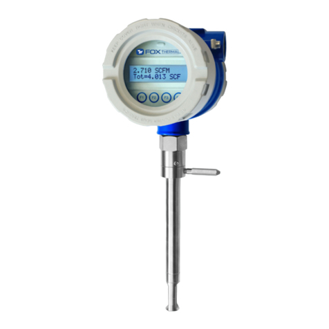
THERMAL MASS FLOW METER
& TEMPERATURE TRANSMITTER
Precision Mass Flow Measurement
An ON
I
CON Brand

Fox FT2A Manuals:
• Fox FT2A Modbus / BACnet MS/TP Manual
• Fox FT2A Probus, DeviceNet, Ethernet Manual
• Fox FT2A View™ Manual
Fox FT2A Manuals:
•
Fox FT2A Modbus / BACnet MS/TP Manual
•
Fox FT2A Probus, DeviceNet, Ethernet Manual
•
Fox FT2A View™ Manual
All Fox Manuals and software available in English only.
Notice
Model FT2A
FOX THERMAL
2
This publication must be read in its entirety before performing any
operation. Failure to understand and follow these instructions could result
in serious personal injury and/or damage to the equipment. Should this
equipment require repair or adjustment beyond the procedures given
herein, contact the factory at:
FOX THERMAL INSTRUMENTS, INC.
399 RESERVATION ROAD
MARINA, CA 93933
TELEPHONE: 831-384-4300
FAX: 831-337-5787
EMAIL: SERVICE@FOXTHERMAL.COM
Download Technical Data Sheets from our website:
www.foxthermal.com
Fox Thermal believes that the information provided herein is accurate;
however, be advised that the information contained herein is NOT
a guarantee for satisfactory results. Specically, this information is
neither a warranty nor guarantee, expressed or implied, regarding
performance, merchantability, tness, or any other matter with respect
to the products; nor recommendation for the use of the product/
process information in conict with any patent. Please note that Fox
Thermal reserves the right to change and/or improve the product
design and specication without notice.

Table Of Contents
Model FT2A
TABLE OF CONTENTS
1. Introduction Page 6
2. Installation (Mechanical) Page 9
a. Straight run requirements Page 10
3. Wiring (Electrical) Page 20
a. Local Wiring Page 23
b. Input Power Page 23
c. Signal Wiring Page 25
d. Alarm Wiring Page 28
e. Remote Switch Page 29
f. Remote Wiring Page 31
4. Operation (Standard Operation) Page 32
a. Start Up Page 32
b. Display Screens Page 33
c. Engineering Screens Page 34
d. Programming Page 35
e. Menu Trees Page 54
5. Maintenance Page 62
6. Troubleshooting Page 68
7. Appendices Page 74
a. Specications Page 74
b. Agency Approvals Page 77
c. FT2A with 2 Gas Curves Page 78
d. Dimensions Page 82
e. Mounting the FT2A Enclosure Page 90
f. Warranty Page 92
g. Returning your meter Page 93
8. Glossary of Terms and Abbreviations Page 94
9. Index Page 96
3

1. Record inside diameter (ID). Ensure the actual
pipe ID matches the pipe ID shown on the
factory calibration certicate. If IDs do not
match, refer to p. 423.
2. Record up/downstream straight-pipe
requirements based on Pipe ID and meter
style (insertion or inline). [refer to p. 19]
3. The Flow Direction Indicator must point in the
direction of ow.
4. Ensure correct probe depth setting. If using 1
½" size pipe, please see note on p. 21.
5. Ensure power wiring and 4-20mA wiring
properly connected. [refer to p. 30 - p. 32
for more information]
6. Ensure remote wiring is correct if remote
option ordered.
[refer to p. 38 - p. 39 for more
information]
7. Verify you have the proper output signal
wiring
[refer to p. 33 - p. 36 for more
information]
8. Power on the ow meter.
9. Check the remaining ow meter settings by accessing the meter settings either through the
front panel of the display or by using the FT2A View™ software tool. Record the settings in the
spaces given for items A - E on the following page.
Use the table below as a guide while using the worksheet on the next page to record your notes.
NOTE! Please read the entire quick-start procedure before beginning installation.
ID Outer
Diameter
(OD)
FLOW
4X = Inline
10X = Insertion
8X = Inline
15X = Insertion
Pipe ID min.
INDICATOR:
- POINT IN DIRECTION
OF FLOW
FLOW
MODEL FT2A
Gas Mass Flowmeter & Temperature Transmitter
FLOW
PIPE
0.87"
(22.098mm)
L
C
FT2A Enclosure
Main Board Electronics Inside Display/Cover
TS7 TS1
TS2
TS8
OPTIONAL
COMMUNICATION
(DEVICENET
PROFIBUS)
ETHERNET
USB
COMMUNICATION
1 2 3
1
1
2
3
4
5
1 2 3
1
2
3
4
5
6
7
8
9
10
11
1
2
3
4
5
6
7
8
TS3
J1
J4
AC POWER DC POWER
REMOTE
SENSOR
WIRING
I/O WIRING
AND
OPTIONAL
MODBUS
COMMUNICATION
#4
#6
#3
#5
#2
#1
Black Dot Denotes Pin #1
Cable Shield
Electronics Enclosure
RED
RED
WHT
WHT
GRN WHT
Shield
GRN
BRN
YEL
BLK
RED
Probe Sensor Wired By Fox
SENSOR
RED*
BLK*
BRN*
WHT*
GRN*
RED
RED
YEL
WHT
WHT
Remote Enclosure
Sensor Wires
TS7 TS1
TS2
TS8
1 2 3 1 2 3
1
2
3
4
5
6
7
8
9
10
11
Initializing...
TS7 TS1
TS2
TS8
1 2 3
1
1
2
3
4
5
1 2 3
1
2
3
4
5
6
7
8
9
10
11
+24VDC
+24VDC
4 to 20mA FLOW RATE
4 to 20mA TEMPERATURE OR
FLOW RATE
24VDC Return
Customer PLC or DCSFT2A
24VDC Return
* (see important note below)
4
Introduction: Quick Start Guide
Model FT2A
INTRODUCTION

5
Introduction: Quick Start Guide
Model FT2A
INTRODUCTION
Item to verify
Serial Number: Serial Number: Serial Number: Serial Number:
1. What is the Pipe ID? ID = ID = ID = ID =
2. Calculate the Upstream/
Downstream straight-pipe
requirements
UP =
DN =
UP =
DN =
UP =
DN =
UP =
DN =
3. a. Is the ow indicator
pointed in direction of
ow?
Y / N Y / N Y / N Y / N
4. Is the probe depth setting
correct?
Y / N Y / N Y / N Y / N
5. Verify proper power wiring
setup
6. Verify proper remote wiring
setup (if ordered)
7. Verify proper input/output
wiring setup
After powering on your meter, check items A - E below by accessing the meter settings either through the front
panel of the meter's display or by using the FT2A View™ software tool.
A. Which ow units have been
set in meter? (SCFM, KG/H,
etc..)
B. Correct values for reference
temperature and pressure?
Y / N Y / N Y / N Y / N
C. Conrm the pipe ID listed
above same as "Pipe_id="
D. Verify the 1st 4mA and
20mA meter settings
4mA =
20mA =
4mA =
20mA =
4mA =
20mA =
4mA =
20mA =
E. Verify the 2nd 4mA and
20mA meter settings
4mA =
20mA =
4mA =
20mA =
4mA =
20mA =
4mA =
20mA =
Your Notes:
Before powering on your meter, use this worksheet to record your notes.
If you are experiencing any problems after completing this procedure, please call the Fox
Thermal Service Department at 831-384-4300 to review this information.

Thank you for purchasing the Model FT2A Thermal Gas Mass Flow Meter and Temperature
Transmitter from Fox Thermal. The Model FT2A is one of the most technically advanced ow
meters in the world. Extensive engineering effort has been invested to deliver advanced
features, accuracy measurement performance and outstanding reliability.
This Instruction Manual contains the electrical and mechanical installation instructions as well
as details for programming, maintaining and troubleshooting the meter.
This manual is divided into the following sections: Introduction, Installation, Wiring, Operation,
Maintenance, Troubleshooting, Appendices, Glossary and Index.
Theory of Operation
The Model FT2A is an innovative Thermal Mass Gas Flow Meter and Temperature Transmitter.
It is microprocessor-based and eld programmable. The FT2A thermal sensor operates on
the law that gases absorb heat. A heated sensor placed in an air or gas stream transfers
heat in proportion to the stream’s mass velocity. There are two sensor elements connected
to a balanced bridge circuit. One sensor element detects the gas temperature and a second
element is maintained at a constant temperature above the gas temperature. The energy
applied to the heated sensor to maintain a constant temperature differential (constant ∆ T) is
directly proportional to the mass ow velocity. The FT2A ow meter maintains accurate ow
measurement over a large temperature and pressure range.
Mass Flow
The Model FT2A measures mass ow; an advantage over other ow meters which measure
volumetric ow rate. Volumetric ow is incomplete because temperature and pressure are
unknown and must be measured separately. For example, the mass ow of a gas depends on
its temperature and pressure. As temperature and pressure changes, the gas volume changes
but not its mass. Therefore a device measuring mass ow is independent of temperature
and pressure. The Model FT2A provides a direct measurement of gas ow in Mass units (kg/
hr, lb/hr), standard units (SCFM, SLPM) or normal units (NM3/hr, NLPM) with no additional
temperature or pressure measurements required.
6
Introduction
Model FT2A
INTRODUCTION

Flow Calibration
The Fox Calibration Lab maintains instrument calibration records on every ow meter. This
data can also be accessed via a computer using FT2A View™ software within the instrument.
Computer-generated calibration documents describe specic instrument details that can be
sorted by serial number, tag number or customer purchase order.
Calibration les include details on process conditions, calibration uid, line size and other
information. All NIST-traceable equipment utilized for the calibration procedure is identied,
as is the calibration history of all reference equipment.
In addition to the Calibration Certicate, a certied ow table that correlates current outputs
with scaled units of ow is produced for each calibrated device.
I/O Description
The FT2A features two galvanically isolated 4-20mA analog outputs, one isolated digital
output, one discrete input and a USB port for communication with a computer.
The rst 4-20mA output is for ow rate. The second 4-20mA output can be congured either
for ow rate or process gas temperature. Both 4-20mA outputs can be scaled by the user. The
digital output can be used for frequency or alarm, is programmable to represent ow rate and
can be scaled for maximum ow/maximum frequency, units-per-pulse or pulse-per-units. The
maximum frequency is 100 Hz.
FT2A View™ interfaces to the USB port and is a free Fox PC-based software program that
displays ow meter readings and permits ow meter conguration. The software is available
for download on the Fox website.
Industry standard communication options are available including optional RS485 Modbus,
BACnet MS/TP, Probus-DP, DeviceNet, or Ethernet Modbus TCP. These serial communication
options can be selected when ordering the meter. Modbus and BACnet may be enabled after
purchase.
7
Introduction
Model FT2A
INTRODUCTION

MODEL FT2A
Gas Mass Flowmeter & Temperature Transmitter
Standard I/O
4 to 20 mA Flow
Contact Input
4 to 20 mA Flow or Temperature
Frequency or Alarm
USB
(Free FT2A View Software)
Outputs and Communications are Galvanically Isolated
Optional Digital Communications
Profibus, DeviceNet, Ethernet
RS485 Modbus, BACnet MS/TP
Standard Digital Communications
24VDC Input Power
100-240VAC Optional
Display and
Configuration Panel
FT2A Functional Diagram
An on-board 2 line x 16 character backlit LCD display shows ow rate, total ow, elapsed
time, process gas temperature and alarms. The display is also used in conjunction with the
Conguration Panel for eld conguration of ow meter settings such as 4-20mA scaling,
frequency output scaling, pipe area, zero ow cutoff, ow ltering or damping, display
congurations, diagnostics and alarm limits.
Fig. 1.1: FT2A Function Diagram
8
Model FT2A
INTRODUCTION
Introduction Installation

Scope
This section describes how to install the Fox Model FT2A Flow Meter and how to get started.
Installation methods will vary according to the ow meter type (insertion or inline).
For Insertion Types:
1. Determine lateral position on the pipe
2. Sensor installation depth
3. Sensor orientation in relation to sensor length and direction of ow
4. Proper tightening of compression tting for mounting meter
For Inline Types:
1. Determine lateral position on the pipe
2. Flow body orientation in relation to direction of ow in pipe
3. Proper tightening of compression tting
Installation procedures must be performed using a combination of the end user’s best
engineering practices, in compliance with local codes, and manufacturer’s recommendations.
General Precautions
The following general precautions should be observed:
1. Exercise care when handling the ow meter to avoid damaging the probe, sensor or
enclosure.
2. Close any unused conduit openings in the enclosure with plugs certied for your
application.
3. The enclosure covers must be closed except during installation.
4. Mounting FT2A in direct sunlight can cause the temperature inside the enclosure
to increase beyond design limits, resulting in failure of LCD display and reduced
component life. It is recommended that a sunshade be installed to avoid direct
sunlight.
5. Ensure the ow direction arrow points in the direction of ow.
6. Do not install the FT2A enclosure near an igniter, igniter-controller or switching
equipment.
7. Do not install an external power supply in a cabinet containing an igniter controller
or switching equipment.
8. Ensure that good engineering practices and applicable industry codes are followed
throughout the installation process.
9. For accurate ow measurement: review ow meter placement instructions before
installation to ensure a proper ow prole in the pipe.
9
Model FT2A
INSTALLATION
Installation

FLOW
10X Pipe ID
Proper
Flow
Profile
15X Pipe ID
Irregular
Profile
Irregular
Profile
FLOW
4X Pipe ID
Proper
Flow
Profile
8X Pipe ID
Branch Outlet
(installed by
customer)
INSERTION
INLINE
Instructions for Flow Meter Lateral Placement
Install the Model FT2A ow meter so that it is far enough away from bends in the pipe,
obstructions, or changes in line sizes to ensure a consistent ow prole. See Fig. 2.1 below for
your meter type.
NOTE! Pipe ID = Inside Diameter.
Fig. 2.1: Upstream and Downstream Pipe IDs for Flow Meters
i
NOTE!
• The probe diameter is ½"
• An irregular ow prole will affect sensor accuracy
NOTE!
•
The probe diameter is
½
"
•
An irregular ow prole will affect sensor accuracy
i
Installation
10
Model FT2A
INSTALLATION

Welding NPT Female Fitting to Pipe
The probe of the FT2A must be installed perpendicular in the pipe to measure ow accurately.
Use the following steps to ensure that the 1" NPT female tting is correctly welded to the pipe.
Directions:
1. Drill a 0.781-inch hole inside the tting through the wall of the pipe (1 wall only).
2. Assemble the compression tting and NPT tting hand tight onto the probe of the FT2A.
3. Insert the probe into the hole in the pipe and use the FT2A probe and compression tting
to align the NPT tting with the hole and the probe perpendicular to the pipe.
4. Tack-weld the NPT female tting carefully onto the pipe.
• Before welding the tting completely, verify the probe is aligned to the center of the
pipe and the hole is centered in the NPT tting (see Figure 2.2).
5. To verify that the correct hole position has been achieved,carefully slide the 0.75-inch
sensor in and out of the NPT female tting and 0.781-inch hole.
WARNING! Do not force the 0.75-inch sensor through the 0.781-inch hole. Forcing it
through the 0.781-inch hole can damage the probe!
6. Verify that the temporary weld of the NPT female tting positions the probe window on the
pipe's centerline.
• Figure 2.2 shows an incorrect welding of the NPT female tting, causing the 0.75-inch
sensor to be "off center".
7. Once the NPT tting is aligned properly, remove the 0.75-inch sensor from the NPT female
tting and nish welding. Then verify the probe is still aligned with the center of the pipe.
8. Set the depth of the ow meter (see "Fig. 2.3: Cross Section of Insertion Sensor Depth in
Pipe" on page 21).
• Do not tighten Swage tting until proper depth of ow meter is determined. See Fig.
2.3.
Fig. 2.2: Alignment of NPT Female Fitting
PIPE
CENTERLINE
CORRECT NPT FEMALE
FITTING
CENTERED
0.75”
HOLE
PIPE
Ø.50"
PROBE
PIPE
CENTERLINE
INCORRECT NPT FEMALE
FITTING
OFF
CENTER
0.75”
HOLE
PIPE
Ø.50"
PROBE
11
Model FT2A
INSTALLATION
Installation

Half Coupling,
3/4" NPT Female
(
Supplied by
Customer
)
Compression Fitting
(Supplied by Fox)
Customer’s Pipe
.87" (22.098 mm)
L
C
Probe Diameter, 1/2”
Gas Mass Flowmeter & Temperature Transmitter
MODEL FT2A
Specic Conditions of Use:
• The ameproof joints of the equipment are not intended to be repaired.
Consult the manufacturer if dimensional information on the ameproof
joints is necessary.
• The amepaths of the equipment are not intended to be repaired. Consult
the manufacturer if repair of the amepath joints is necessary.
• Follow the manufacturer's instructions to reduce the potential of an
electrostatic charging hazard.
Specic Conditions of Use:
•
The ameproof joints of the equipment are not intended to be repaired.
Consult the manufacturer if dimensional information on the ameproof
joints is necessary.
•
The amepaths of the equipment are not intended to be repaired. Consult
the manufacturer if repair of the amepath joints is necessary.
•
Follow the manufacturer's instructions to reduce the potential of an
electrostatic charging hazard.
Installation Depth
The installation depth of the sensor in the pipe is dependent on the pipe size. To get the most
accurate reading, proper placement of the sensor window within the pipe is necessary. As
shown in Fig 2.2, the end of the sensor window should be 0.87" past the center line of the pipe.
Fig. 2.3: Cross Section of Insertion Sensor Depth in Pipe
12
Model FT2A
INSTALLATION
Installation

FLOW
Flow Direction Arrow
Gas Mass Flowmeter & Temperature Transmitter
MODEL FT2A
CUSTOMER
PIPE
Note: Rotational
misalignment
should not exceed
±2°
TOP VIEW
FRONT VIEW
+2°
-2°
FLOW
CUSTOMER
PIPE
Fig. 2.4: Orientation of Type Flow Meter
iNOTE! Some ow meters are shipped with the sensor elements that are offset (see
gure 2.4). Others are shipped with sensors that have equal length elements (see
gure 2.5). The sensor type supplied was selected at the factory to be the best suited
for your application. Follow the appropriate sensor orientation instructions.
13
Model FT2A
INSTALLATION
Installation

+2°
-2°
FLOW
FLOW
+2°
-2°
FLOW
FLOW
Unequal Length Sensor Elements
Install the shorter sensor element upstream from the longer one.
Fig. 2.5: Unequal Length Sensor Elements
Equal Length Sensor Elements
Install ow meter with both sensor elements facing the ow stream within ±2˚.
Fig. 2.6: Equal Length Sensor Elements
Installation
14
Model FT2A
INSTALLATION
14
INSTALLATION
Model FT2A
INSTALLATION

Mounting Instructions - Compression Fittings
The Model FT2A is mounted through a 7/8" hole and a ¾" female NPT half coupling provided
in the customer's pipe. Insertion style ow meters are not designed for use in pipes smaller
than 1½".
• Install the compression tting into the ¾-inch female NPT half coupling.
• When installing in a 2" pipe or larger, install the end of the probe 0.87" past the center
line of the pipe and tighten the compression tting nut (refer to gure 2.2 on p. 12).
• When installing into a 1½" pipe carefully install the probe into the pipe until it touches
the opposite wall and pull back 0.1". Tighten the compression tting nut.
• While holding the tting body steady, tighten the nut one and one-quarter turn to the 9
o'clock position. See Figure 2.6.
CAUTION! For a 1½" pipe, do not tighten compression tting without 0.2” distance
from wall or damage to probe will occur.
CAUTION! Once the compression tting ferrule is locked onto the probe, the
probe can be removed or rotated, but the insertion depth is locked in place.
CAUTION! If the stainless steel or teon ferrules are not properly tightened, and/or
the recommended pressure is exceeded, the ferrules can slip on the stainless steel
tubing causing damage to the meter or bodily harm.
Fig. 2.7: Proper Tightening of the Compression Fitting Nut
15
Model FT2A
INSTALLATION
Installation

Installation of a New Retractor Assembly
1. Remove collar clamp from probe using a 3/16" Hex Key.
2. Remove meter probe from retractor assembly and leave the ball valve open. Keep the collar
spacer on the probe so it is not misplaced.
3. Install the valve assembly on the pipe, by tightening the Hex Nipple with a 1 3/8" wrench.
Fig. 2.8: Retractor Assembly With and Without Probe Installed
Gas Mass Flowmeter & Temperature Transmitter
MODEL FT2A
Hex Nipple
Collar clamp
Collar
spacer
16
Installation
Model FT2A
INSTALLATION

4. Carefully slide the probe through the retractor assembly and through the hole to see if there
is interference by touching the pipe wall with the end of the probe on the far side or until the
probe cannot go deeper. Remove the probe. Remove the retractor and rework the hole, if
required.
Fig. 2.9: Verify Probe Insertion
Gas Mass Flowmeter & Temperature Transmitter
MODEL FT2A
17
Installation
Model FT2A
INSTALLATION

5. Using the equation (L + D/2 + 0.73") from Figure 2.9, calculate the insertion depth and mark on
the probe while measuring from the end of the probe.
6. The Retractor Clearance table of Figure 2.9 lists the space required to remove the meter from
the retractor. Use the model code of your meter to determine the dimension.
Fig. 2.10: Determining and Marking Insertion Depth
"D"
.87
[22.098mm]
"D/2"
"L"
HALF COUPLING
3/4 INCH NPT, FEMALE
"RC"
RETRACTOR
CLEARANCE
MARK ON PROBE
INSERTION DEPTH:
L + D/2 + .87"
RETRACTOR CLEARANCE
CODE
23.9" [60.7 CM]15R
26.5" [68.3 CM]18R
32.5" [83.6 CM]24R
38.5" [98.8 CM]30R
44.5" [114.0 CM]36R
"RC" DIMENSION
Gas Mass Flowmeter & Temperature Transmitter
MODEL FT2A
18
Installation
Model FT2A
INSTALLATION

7. Insert probe back into the retractor to the depth mark and hand-tighten the compression
tting.
8. Verify that ow direction indicator is in line with pipe and in the direction of ow.
Fig. 2.11: Installed Retractor
9. Fully tighten compression tting (refer to "Mounting Instructions - Compression Fittings" on
page 15).
Gas Mass Flowmeter & Temperature Transmitter
MODEL FT2A
Swage Nut &
Ferrules
Flow Direction
Indicator
Swage Fitting
Collar Clamp
Collar Spacer
Bracket
19
Installation
Model FT2A
INSTALLATION

Wiring Instructions
Wire the FT2A by opening the enclosure cover, bringing customer supplied wires in through the
conduit openings and connecting to the terminal blocks. The FT2A has two conduit openings to
maintain separation between AC input power and output signal wiring. To eliminate the possibility
of noise interference; use a separate conduit for AC power, cut all wires short for a minimum service
loop and keep the wires within the area of the FT2A internal metal shields.
Wiring Precautions
• WARNING - DO NOT OPEN THE ENCLOSURE WHEN ENERGIZED OR AN EXPLOSIVE
ATMOSPHERE IS PRESENT.
• All plumbing and electrical installations of ow meters must be in compliance with local
codes, the end user’s best engineering practices, and manufacturer’s recommendations.
• An external power disconnect and 16A over-current protection are required for the AC
and DC powered FT2A.
• Do not install the FT2A enclosure near an igniter, igniter-controller or switching
equipment.
• Do not install an external power supply in a cabinet containing an igniter controller or
switching equipment.
• This ow meter contains components that can be damaged by static electricity. You must
discharge yourself by touching a grounded steel pipe or other grounded steel material
prior to working inside this ow meter.
• For the remote sensor option, the serial number of the electronics enclosure must match
the remote sensor probe.
• Close any unused conduit entries using suitably certied plugs
•
Installation wiring: Cut all wires short for a minimum service loop.
Obtain the correct
length for the FT2A wires using one of these methods:
• Trim the wires to extend 5 inches out of the enclosure after the conduit and wires are
routed to the FT2A.
• Trim the wires to extend 6 inches from the end of the conduit before attaching them
to the FT2A.
Power Wiring
For power wiring, use stranded copper wire, no larger than 16-gauge. If an external 24VDC power
source is used, twisted pair shielded cable is recommended. Supply connection wiring must be
rated for at least 90°C.
Grounding
The enclosure must be properly grounded with a quality earth ground. 16 gauge, stranded wire is
recommended.
Wiring
20
Model FT2A
WIRING
Other manuals for FT2A
1
Table of contents
Other Fox Thermal Measuring Instrument manuals

Fox Thermal
Fox Thermal FT1 User manual

Fox Thermal
Fox Thermal FT3 User manual

Fox Thermal
Fox Thermal FT1 User manual

Fox Thermal
Fox Thermal FT4A User manual

Fox Thermal
Fox Thermal FT2A User manual

Fox Thermal
Fox Thermal FT3 User manual

Fox Thermal
Fox Thermal FT1 User manual

Fox Thermal
Fox Thermal FT1 User manual
Popular Measuring Instrument manuals by other brands

Rohde & Schwarz
Rohde & Schwarz ZPV manual

evertz
evertz 7880SA user manual

HP
HP 37718A OmniBER 718 Installation and verification manual

Agilent Technologies
Agilent Technologies ADM2000 operating instructions

Veeder-Root
Veeder-Root SERIES 7886 Installation, operation and service instructions

V2
V2 HURRICANE-RS quick start guide