Fröling RBG 3200 User manual

Operating instructions
Control Panel RBG 3200
Core module version 50.04 - Build 05.19
Translation of original German version of operating instructions for operators.
Read and follow all instructions and safety instructions.
All errors and omissions excepted.
B0640421_en | Edition 06/09/2021

Contents
ii B0640421_en | Operating instructions Control Panel RBG 3200
1 General ......................................................................................................................................................... 4
1.1 About these instructions ....................................................................................................................... 4
1.2 Safety information................................................................................................................................. 4
2 Installing the RBG 3200 .............................................................................................................................. 5
2.1 Connecting the bus cable ..................................................................................................................... 5
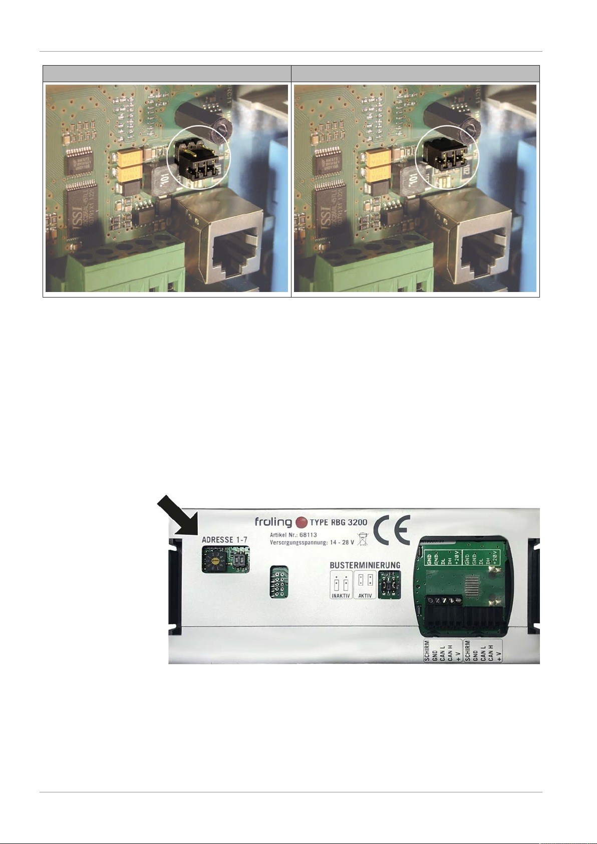
2.2 Setting end jumpers.............................................................................................................................. 5
2.3 Setting the module address .................................................................................................................. 6
2.4 Initial startup ......................................................................................................................................... 7
3 Overview of the basic functions ................................................................................................................ 8
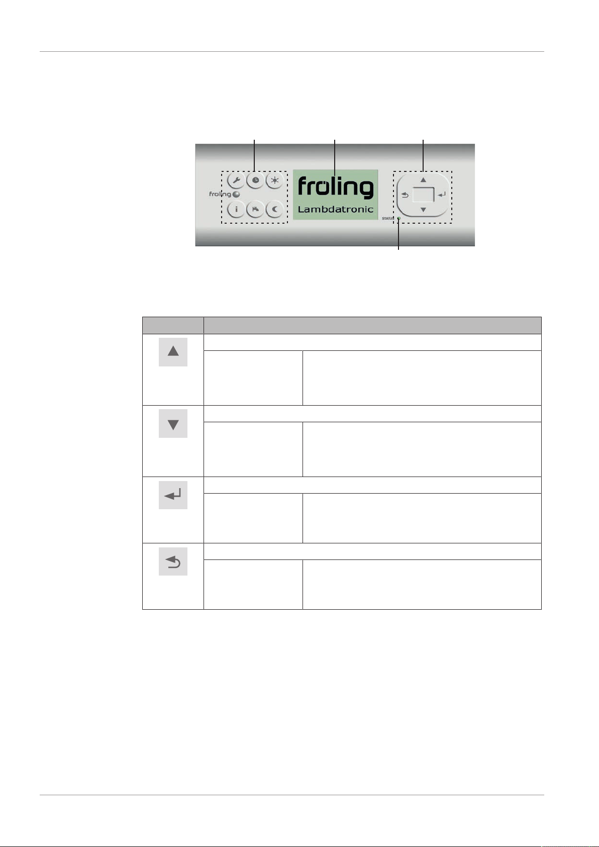
3.1 Control keys and display....................................................................................................................... 8
3.1.1 Navigation keys.......................................................................................................................... 8
3.1.2 Status LED................................................................................................................................. 8
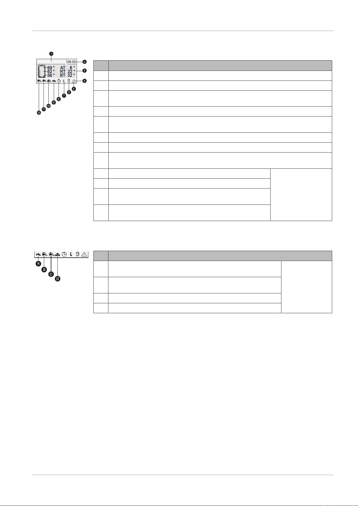
3.1.3 Graphic display .......................................................................................................................... 9
3.2 Function keys........................................................................................................................................ 10
3.2.1 Info key ...................................................................................................................................... 10
3.2.2 Service program key .................................................................................................................. 11
3.2.3 DHW tank program key.............................................................................................................. 11
3.2.4 Party program key...................................................................................................................... 12
3.2.5 Setback program key ................................................................................................................. 13
4 Operation...................................................................................................................................................... 14
4.1 Setting parameters ............................................................................................................................... 14
4.2 Setting times ......................................................................................................................................... 14
4.2.1 Deleting a time window .............................................................................................................. 15
5 Parameters overview................................................................................................................................... 16
5.1 Heating ................................................................................................................................................. 16
5.1.1 Heating - Status ......................................................................................................................... 16
5.1.2 Heating - Temperatures ............................................................................................................. 17
5.1.3 Heating - Times.......................................................................................................................... 18
5.2 Water .................................................................................................................................................... 18
5.2.1 Water - Status ............................................................................................................................ 18
5.2.2 Water - Temperatures................................................................................................................ 19
5.2.3 Water - Times ............................................................................................................................ 19
5.3 Solar ..................................................................................................................................................... 19
5.3.1 Solar - Status ............................................................................................................................. 19
5.3.2 Solar - Temperatures ................................................................................................................. 21
5.4 Buffer tank ............................................................................................................................................ 21
5.4.1 Buffer tank - Status .................................................................................................................... 21
5.4.2 Buffer tank - Temperatures ........................................................................................................ 22
5.5 Boiler 2.................................................................................................................................................. 22
5.5.1 Boiler 2 - Status ......................................................................................................................... 22
5.5.2 Boiler 2 - Temperatures ............................................................................................................. 23
5.6 Difference regulator .............................................................................................................................. 24
5.6.1 Difference regulator - Status ...................................................................................................... 24
5.7 Circulation pump................................................................................................................................... 24
5.7.1 Circulation pump - Status........................................................................................................... 24
5.7.2 Circulation pump - Temperatures .............................................................................................. 25
5.7.3 Circulation pump - Times ........................................................................................................... 25
5.8 System.................................................................................................................................................. 25
5.8.1 System - Current values ............................................................................................................ 25
5.8.2 System - Error............................................................................................................................ 25
5.8.3 System - Basic display parameters............................................................................................ 26
5.8.4 System - Language.................................................................................................................... 26

Contents
B0640421_en | Operating instructions Control Panel RBG 3200 iii
5.8.5 System - Current Date ............................................................................................................... 26
5.8.6 System - Current Time............................................................................................................... 27
5.8.7 System - Current User Level...................................................................................................... 27
6 Troubleshooting .......................................................................................................................................... 28
6.1 Procedure for fault messages............................................................................................................... 28

1 | General
4 B0640421_en | Operating instructions Control Panel RBG 3200
1 General
1.1 About these instructions
Please read and follow the operating instructions, in particular the safety information
contained therein. Keep them available next to the boiler.
These operating instructions include important information about operation, electrical
connection and troubleshooting. The parameters shown depend on the set boiler type
and the system configuration!
The constant further development of our products means that there may be minor
differences from the pictures and content. If you discover any errors, please let us know:
1.2 Safety information
DANGER
When working on electrical components:
Risk of electrocution!
When work is carried out on electrical components:
rAlways have work carried out by a qualified electrician
rObserve the applicable standards and regulations
ÄWork must not be carried out on electrical components by unauthorised persons

Installing the RBG 3200 | 2
B0640421_en | Operating instructions Control Panel RBG 3200 5
2 Installing the RBG 3200
take cable through
rFit the holding frame as shown at the desired position in the room using the
anchors and screws provided
ÄThe large grommet must be on the left!
ÄIt is recommended to install the device above a flush-mounted socket so that
there is plenty of space to stow away the bus cable.
2.1 Connecting the bus cable
For the bus connections between the individual modules, cable type LIYCY paired
2x2x0.5 should be used. The connection to the 5-pin plugs should be carried out
according to the following diagram:
Braided shield
white
green
yellow
brown
Braided shield
white
green
yellow
brown
2.2 Setting end jumpers
NOTICE!To ensure smooth running of the bus system, the jumper must be set
on the first and last module.
When using a bus repeater, the two galvanically separated sub-networks must be
considered separately. The jumpers for each network must be set on the first and last
module.

2 | Installing the RBG 3200
6 B0640421_en | Operating instructions Control Panel RBG 3200
End jumper not set End jumper set
If the contacts at the base of the end jumper are not bridged (image left), it is referred
to as “not set". In this case there is no bus termination. If the contacts are closed
(image right), the end jumper is set and the bus connection is terminated.
2.3 Setting the module address
You must set the required order with the module addresses for the RBG 3200 (display
module). The standard boiler comes with a display module (boiler display) with the
address 0 (except S3 Turbo with S-Tronic controller). If you, therefore, install an
additional display module, set it to address 1 so that the standard hydraulic system
settings do not need to be reconfigured. Set all further RBG 3200s module addresses
in ascending order (2 to 7).
Important! Only set the module address when the device is disconnected from
the power supply!

Installing the RBG 3200 | 2
B0640421_en | Operating instructions Control Panel RBG 3200 7
2.4 Initial startup
NOTICE
You should have the initial startup carried out by the authorised heating engineer from
Froling customer services.
Once you have connected the device to the power supply and switched on the main
switch, the start logo will appear and the control will perform a system check.
After the system check the basic display will appear.
The default basic display provides information about the two main parameters,
however it can be customised to the user's individual requirements.
Ü "System - Basic display parameters" [}26]

3 | Overview of the basic functions
8 B0640421_en | Operating instructions Control Panel RBG 3200
3 Overview of the basic functions
3.1 Control keys and display
Function keys Visual display Navigation keys
Status LED
3.1.1 Navigation keys
The navigation keys are used to move within the menu and to change parameter values.
Key Function for
UP arrow
navigation: move up a menu level
parameter change: depending on how long the key is pressed:
- short: increase value
- long: increase value in increments of 10
- long (>10 secs): increase value in increments of 100
DOWN arrow
navigation: move down a menu level
parameter change: depending on how long the key is pressed:
- short: reduce value
- long: reduce value in increments of 10
- long (>10 secs): reduce value in increments of 100
Enter
key
navigation: go to selected menu
parameter change: release the parameter for editing, or save parameter
value after changing
Back
key
navigation: go back up a menu level
parameter change: depending on how long the key is pressed:
- short: do not save parameter
- long: back to basic display without saving
3.1.2 Status LED
The status LED shows the operating status of the system:
▪ GREEN flashing (interval: 5 sec OFF, 1 sec ON):
▪ GREEN constant: BOILER SWITCHED ON
▪ ORANGE flashing: WARNING
▪ RED flashing: FAULT

Overview of the basic functions | 3
B0640421_en | Operating instructions Control Panel RBG 3200 9
3.1.3 Graphic display
Heating
Ref. Description
1 Shows operating status or menu name
2 Shows the current time
3 Displays the main values in the basic display (adjustable)
menu contents, parameters and info texts
4 Status toolbar
5 Displayed when a fault is pending.
Press the info key to display texts describing the fault and the solution
6 Shows the storage tank loading status (storage tank is optional)
7 Indicates that an info text is displayed. Info texts are also identified by a frame
8 Shows which function is active
Ü "Function keys" [}10]
9 Shows that the DHW tank loading pump is active Only shown in the
basic display
!
10 Shows that the storage tank loading pump is active
11 Shows that the heating circuit pump of the 2nd heating circuit is
active
12 Shows that the heating circuit pump of the 1st heating circuit is
active
In the service technician user level, the function of the relevant components is also shown
in the individual status menus by the corresponding status display:
Ref. Description
A Shows whether the storage tank (or oil boiler) is hot enough for hot
water preparation
Only for service
technicians in the
status menus
B Shown when the DHW tank or return temperature control pump is
active
C Shown when the heating circuit or storage tank loading pump is active
D Shows the status of the heating circuit mixer

3 | Overview of the basic functions
10 B0640421_en | Operating instructions Control Panel RBG 3200
3.2 Function keys
The function keys of the key control partially have dual functions. Short or long pressing
of the keys can access different functions (see below):
short keystroke …….. < 1 sec
long keystroke …….. > 4 sec
3.2.1 Info key
Keystroke Function
short Shows plain text information about the menu items or fault
messages
long Choose language: Deutsch, English, Francais, Italiano, Slovenski,
Cesky, Polski, Svenska, Espanol, Magyar, Suomi, Dansk,
Nederlands, Russian, Serbian
The info key can be pressed at any time and always shows information about the current
menu item or the current fault message. Fault messages take highest priority.
Info key in normal mode:
In normal operation (without pending fault messages)
the info key can be pressed to display information or
an explanation for every menu item or parameter.
The info text is also identified by the frame and the
info symbol in the status line.
Info key when there is a pending fault:
Heating
Boiler
Flue gas
Error no. 60
Sensor in DHW tank 01
faulty
If a fault has been acknowledged after arising, but not
resolved, this is shown by a warning symbol at the
bottom right on the status line.
Pressing the info key calls up the information on the
currently pending fault message again.
Procedure for troubleshooting:
Ü "Troubleshooting" [}28]

Overview of the basic functions | 3
B0640421_en | Operating instructions Control Panel RBG 3200 11
3.2.2 Service program key
Keystroke Function
Short Chimney
sweep
Only with boiler display!
NOTICE!See operating instructions for boiler
controller!
Long Service mode Only with boiler display!
NOTICE!See operating instructions for boiler
controller!
3.2.3 DHW tank program key
Keystroke Function
short One-off manual loading of domestic hot water. The function is
indicated during DHW tank loading by the tap symbol in the
status line. After loading, the mode that was previously set
becomes active again.
long Only with boiler display!
IMPORTANT! See operating instructions for boiler
controller!

3 | Overview of the basic functions
12 B0640421_en | Operating instructions Control Panel RBG 3200
3.2.4 Party program key
Keystroke Function
Short The allocated heating circuit is switched to
daytime mode after an optional change of the
room temperature setpoint until the end of the
next heating phase or until automatic mode is
activated.
Long The allocated heating circuit and the domestic
water heating for the allocated DHW are
activated for 6 hours.
Activate party mode
After you press the party mode key, an input field for optionally changing the
"Temperature setpoint in the room" will appear on the display. If you do not
press any other key, daytime mode will be launched for the allocated heating
circuit at the preset temperature setpoint until the end of the next heating
phase or until automatic mode is activated.
After pressing the enter key, set the "Temperature setpoint in room" using the
UP and DOWN arrow keys.
After confirming by pressing the enter key, the info text shown will appear and
daytime mode will be active for the allocated heating circuit until the end of
the set time or until automatic mode is activated.

Overview of the basic functions | 3
B0640421_en | Operating instructions Control Panel RBG 3200 13
3.2.5 Setback program key
Keystroke Function
Short After an optional change to the setback
temperature the heating circuit controller remains
in setback mode until the start of the next heating
time or until activation of another mode.
Long The room temperature is reduced to the preset
setback temperature until another mode is
activated.
Activate setback mode
After you press the setback mode key, an input field for optionally changing the
"Setback temperature setpoint in room" will appear on the display. If you do not
press any other key, setback mode will be launched at the preset "Setback
temperature setpoint" for the allocated heating circuit until the end of the next
heating phase or until automatic mode is activated.
After pressing the enter key, you can set the "Setback temperature setpoint in
room" using the UP and DOWN arrow keys.
After confirming by pressing the enter key, the info text shown will appear and
setback mode will be active for the allocated heating circuit until the end of the set
time or until automatic mode is activated.

4 | Operation
14 B0640421_en | Operating instructions Control Panel RBG 3200
4 Operation
4.1 Setting parameters
Unlock parameter
for processing
Navigate to the
desired parameter
Save value and go back
Back without saving
larger
smaller
4.2 Setting times
The desired time window for the component can be set in the "Times" submenu in the
individual menus of the heating components (heating circuits, DHW tanks ...). The
structure of the time menu and the procedure for changing the times are always the
same.
Example - Setting times for heating circuit 01:
In the "Heating" menu -> "Times":
Heating Circuit 01
Heating Times
Times
Times
Current
program
Change program
Default
program
Current settings for the individual weekdays are displayed.
Pressing the arrow keys changes to the next/previous weekday.
See example below…
The factory-set times are loaded by confirming again (06:00 –
22:00).
Caution - the customer specific time settings are lost in the process!
… In the "Change program" menu:

Operation | 4
B0640421_en | Operating instructions Control Panel RBG 3200 15
Abort without
saving
Change program
Which day do you want to
change?
Change program
MON - FRI
Which day do you want to
change?
SUN MON - FRI?
Save and go back
After pressing the enter key you can select the day or the time
period, for which the heating times are to be set:
- MO, TU, .., SU
- MO - FR
- SA - SU
- SAME ALL DAYS
After pressing the enter key again the time window for the desired
day/time period is displayed.
Up to 4 different heating times can be entered sequentially here.
When the enter key is pressed, the cursor jumps to the next
position, even if no time has been entered. If the cursor is in the last
position, pressing the enter key saves the time window and
switches to the previous menu.
4.2.1 Deleting a time window
To delete a time window, the end time of the desired time window must be put to
24:00. If you press the up arrow key repeatedly, the time disappears and is replaced
by dashes. Then carry out the same process with the start time. After the enter key
has been pressed repeatedly, the changes are adopted and it returns to the previous
menu.

5 | Parameters overview
16 B0640421_en | Operating instructions Control Panel RBG 3200
5 Parameters overview
5.1 Heating
5.1.1 Heating - Status
Basic
display Heating Heating
circuit 1 State
Heating circuit mode
Display and setting the heating circuit mode:
Auto:
Automatic: heating phases according to the set heating times
Extra heating:
The heating circuit is regulated to the set room temperature with no time limitation.
To cancel this function, activate another mode/function
Setback:
Setback mode; the current or next heating phase is ignored
Continuous setback mode:
Heating circuit remains in setback mode until another mode is activated
Party:
Party mode; the current or next setback phase is ignored
OFF:
Switched off; heating circuit deactivated, only frost protection!
Actual flow temperature
Display of the current flow temperature.
Flow temperature setpoint
Display of the calculated flow temperature setpoint.
Room temperature
Prerequisite: Heating circuit used in conjunction with remote control
Display of the current room temperature.
Outside air temperature
Display of the current outside air temperature.

Parameters overview | 5
B0640421_en | Operating instructions Control Panel RBG 3200 17
5.1.2 Heating - Temperatures
Basic display Heating Heating circuit 1 Temperatures
Desired room temperature during heating mode
Prerequisite: Heating circuit used in conjunction with remote control
Room temperature which is regulated during the set heating times.
Desired room temperature during setback mode
Prerequisite: Heating circuit used in conjunction with remote control
Room temperature which is regulated outside of the set heating times.
Flow temperature SP at outside air temperature of +10°C
First setting point for definition of heating curve.
Flow temperature SP at outside air temperature of -10°C
Second setting point for definition of heating curve.
Outside air temperature
Flow temperature
Example for
underfloor heating
Example for
radiators
Reduction of flow temperature in setback mode
The flow temperature is reduced by this value during setback mode.
External temperature, at which heating circuit pump switches off in heating mode
If the outside air temperature exceeds this value during heating, the heating circuit pumps and
mixing valve are deactivated.
External temperature, at which heating circuit pump switches off in setback mode
If the outside air temperature falls below this value in setback mode, the heating circuit pumps
and mixing valve are activated.
Frost protection temperature
If the room temperature or the flow temperature is lower than the set value, the heating circuit
pump will be switched on and the heating circuit mixer keeps to the maximum heating circuit
flow temperature that is set.

5 | Parameters overview
18 B0640421_en | Operating instructions Control Panel RBG 3200
From which temperature at storage tank top should the overheating protection be
activated?
If the temperature at top storage tank exceeds the set value, the heating circuit is activated
regardless of mode (boiler, remote control) and set heating times. The flow temperature is
controlled to the value set in the parameter “Flow temperature SP at outside air
temperature of -10°C”. The function will remain active until the value falls below 2°C.
Recommendation: The overheating protection should be assigned to a high temperature
heating circuit (e.g. radiators).
5.1.3 Heating - Times
Basic display Heating Heating circuit 1 Times
Ü "Setting times" [}14]
5.2 Water
5.2.1 Water - Status
Basic display Water State
DHW tank top temperature
Current temperature of the DHW tank. If the time window for DHW tank loading is reached and
the temperature falls below the value set under parameter “Reload if DHW tank
temperature is below“, the DHW tank will be loaded. The DHW tank is loaded either until
the time window has elapsed or the temperature set under “Desired DHW tank
temperature“ has been reached.
DHW tank bottom temperature
Prerequisite: Solar panel system is regulated by Froling!
Current temperature in the area of the reference sensor of the solar panel system.
DHW tank pump control
Specifies the speed of the DHW tank pump as a percentage of maximum speed.

Parameters overview | 5
B0640421_en | Operating instructions Control Panel RBG 3200 19
5.2.2 Water - Temperatures
Basic display Water Temperatures
Set DHW temperature
When this DHW temperature is reached, DHW tank loading is stopped.
Reload if DHW tank temperature is below
If the DHW tank temperature falls below the value set here, the time window is active and the
loading source (boiler or buffer tank) indicates the set loading increase, and the DHW tank
loading is started.
5.2.3 Water - Times
Basic display Water Times
Ü "Setting times" [}14]
5.3 Solar
5.3.1 Solar - Status
Basic display Solar State
Collector temperature
Display of the current temperature at the solar collector.
Top storage tank solar sensor
Display of the current temperature at the solar reference sensor in the top part of the buffer
tank.
Solar temperature buffer tank bottom
Display of the current temperature at the solar reference sensor in the lower part of the buffer
tank.
Actual power from solar heat meter [kW]
Display of the current output which is generated by the solar collector. The calculation of the
output is only performed either when a per litre output of the collector pump has been set or an
external volume pulse transmitter is used. In order to perform the calculation more precisely,
the use of a collector return sensor is recommended.

5 | Parameters overview
20 B0640421_en | Operating instructions Control Panel RBG 3200
Flow through [l/h]
Prerequisite: External volume pulse transmitter installed
Display of the water quantity currently being pumped through the solar collector.
Todays yield [kWh]
Display of the heat quantity that has been supplied by the solar panel system today.
Daily yield 1 ... 6 days ago [kWh]
Shows the historical progression of the solar panel system. The yields of the last 6 days are
available.
Total yield [kWh]
Display of the heat quantity which has been supplied by the solar panel system since
activation of the heat meter.
DHW tank bottom temperature
Current temperature in the area of the reference sensor of the solar panel system.
Heat exchanger sec. return temperature (line to buffer tank)
Prerequisite: Hydraulic system 12 or 13
Current temperature at heat exchanger flow on the secondary side.
Collector pump runtime
Display of the total runtime of the collector pump.
Collector pump control
Display of the current speed of the collector pump as a percentage of maximum speed.
Pump between heat exchanger and buffer tank
Prerequisite: Hydraulic system 12 or 13
Display of the current speed of the pump between heat exchanger and buffer tank.
Pump between heat exchanger and DHW tank
Prerequisite: Hydraulic system 12
Display of the current speed of the pump between heat exchanger and DHW tank.
Diverter valve for top/bottom coils
Prerequisite: Hydraulic system 12 or 13
Current control of the isolating valve on the solar side.
▪0% … bottom buffer tank
▪100% … top buffer tank
Outfeed: 80°C / RL: 50°C
P: 0.0 kW / DFL: 0
Today: 0 kWh
Total: 0 kWh
▪OUTFEED: Current collector flow temperature
▪Return:Current collector return feed temperature
▪P:Current output which is generated by the solar collector
▪DFL:Current flow rate of solar collector
▪Today: Heat quantity that has been produced by the solar panel system today
▪Total: Heat quantity that has been produced since activation of the solar panel system
Table of contents