5
BDF200-SD
BDF200-FB
Operating instructions
Control panel with emergency stop
EN
5. Combinations and functions of control elements
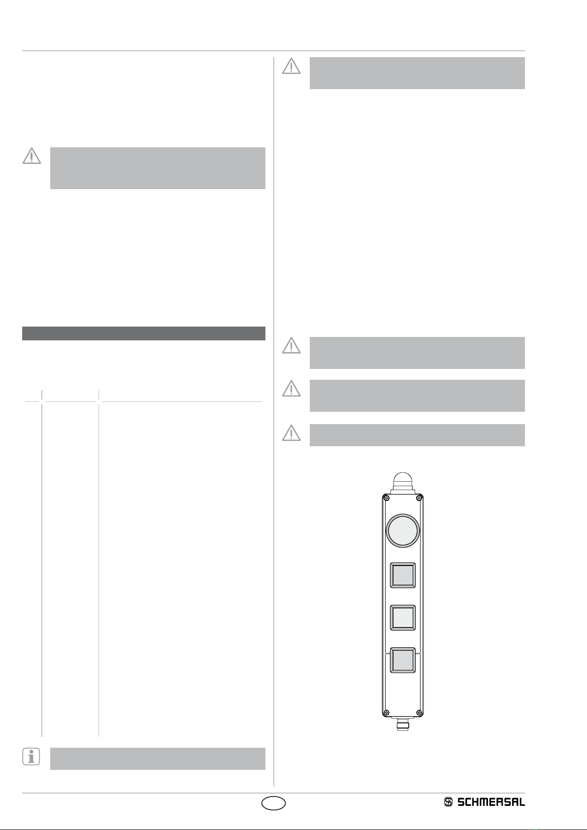
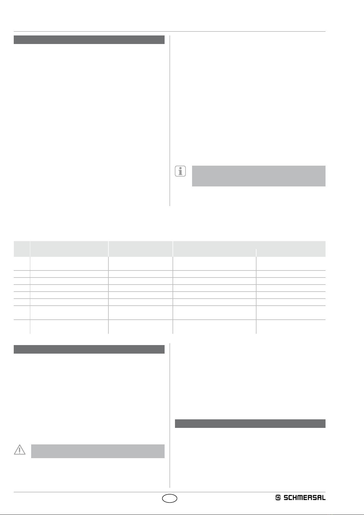
5.1 Combination possibilities of control elements
Pos. 1
Pos. 2
Pos. 3
Pos. 4
optional:
- G24 indicator lamp red / green
Position 1:
- NH, emergency stop impact button
- NHK, emergency stop impact button with collar
Position 2 and position 3:
- Illuminated pushbutton LT
- Illuminated signal LM
- Pushbutton DT
- Mushroom push button PT
- WS2./ WT2., selector switch / button, 2 positions
- WS3./ WT3., selector switch / button, 3 positions
- WTS3., selector button switch, 3 positions
- SWS20 key selector switch, 2 positions
Position 4:
- Illuminated pushbutton LT
- Illuminated signal LM
- Pushbutton DT
- Mushroom push button PT
5.2 Emergency stop function
The emergency stop impact button switches off the safety OSSDs.
Release details of the emergency stop impact button are transmitted to
the control system via the response byte in the SD/FB protocol.
The bit assignment in the SD/FB response byte is as follows:
Position 1: Emergency stop
• Unactuated Authorised operation: Response bit 0 = 1
• Actuated Switched off: Response bit 0 = 0
5.3 Mode of operation of the safety outputs
The safety outputs of the emergency stop function can be integrated
directly into the safety-relevant part of the user control system for circuit
connection. Actuation of the emergency stop impact button causes
immediate deactivation of the safety outputs.
Any error that does not immediately affect the functionality of
the emergency stop function (e.g. ambient temperature too high,
interference potential at safety output, short circuit) will lead to a
warning message and delayed shut-down of the safety outputs.
safety outputs are disabled if the error warning is active for 30 minutes.
Once the error has been rectified, it can be acknowledged by actuating
and disengaging the emergency stop impact button. The safety outputs
enable and allow a restart. Error acknowledgement can be carried out
by setting / deleting bit 7 in the SD/FB query telegram.
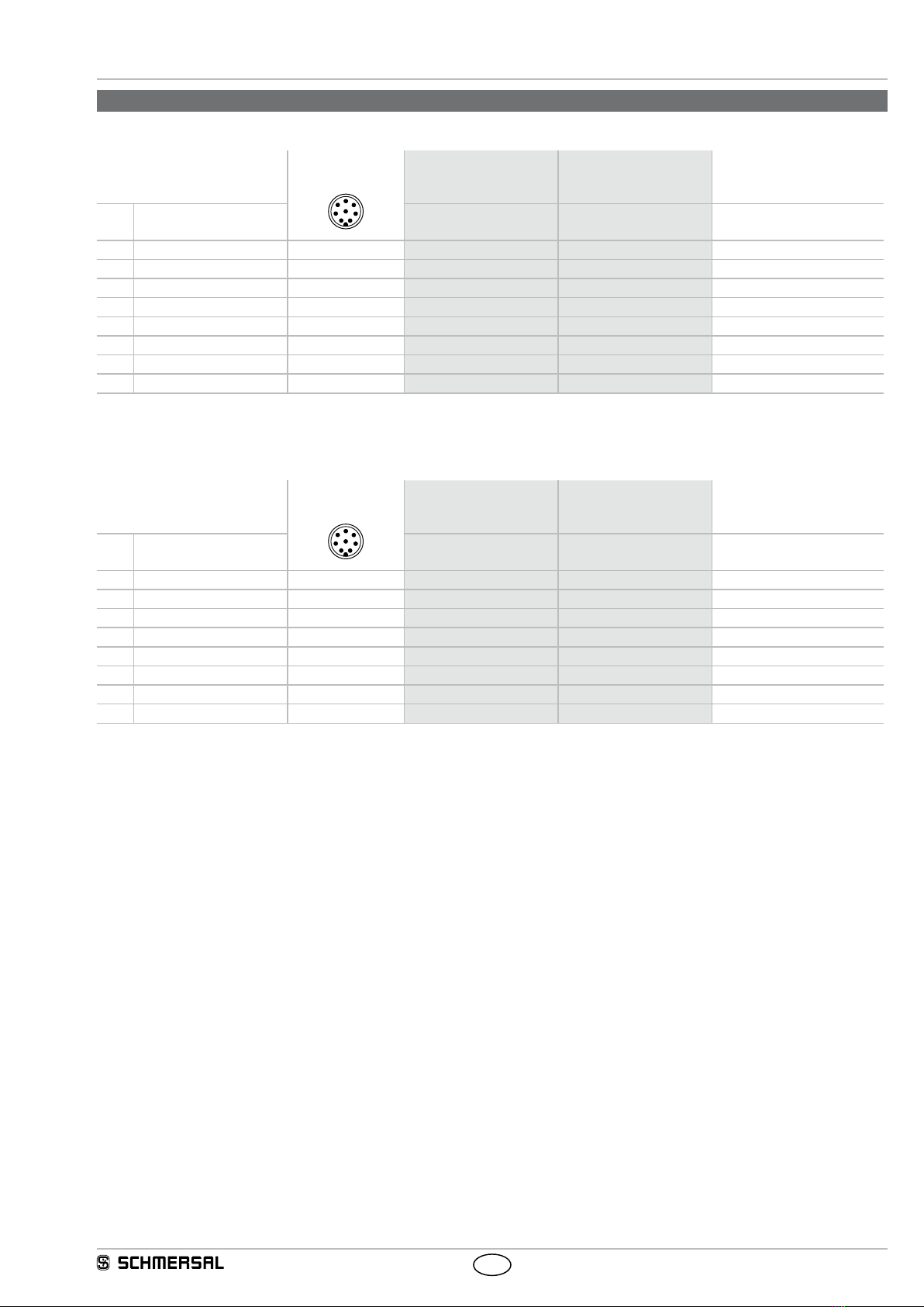
5.4 Function of the command and signalling devices
The non-safety signals of the command devices are transmitted to
the control system via the response byte in the SD/FB protocol. The
Illuminated signals are controlled by the control system via the query
byte in the SD/FB protocol.
The bit assignment of the SD/FB response byte / query byte is as follows:
Position 2:
Illuminated pushbutton, indicator lights, pushbutton and
mushroom pushbutton
LT.., LM.., DT.., PT..
• Pushbutton function NO contact Response bit 1 = 1
NC contact: Response bit 2 = 0
• Indicator lights LED Query bit 3
Maintained selector switch / spring-return selector switch,
2 positions:
WS2., WT2., SWS20, SWT20
1
0
• Position 0 NO contact: Response bit 1 = 0
NC contact: Response bit 2 = 1
• Position 1 NO contact: Response bit 1 = 1
NC contact: Response bit 2 = 0
Maintained selector switch / spring-return selector switch,
3 positions:
WS3., WT3., WTS3.
• Position 1 NO contact Response bit 1 = 0
0
1
2
NC contact Response bit 2 = 0
• Position 0 NO contact: Response bit 1 = 0
NC contact Response bit 2 = 1
• Position 2 NO contact: Response bit 1 = 1
NC contact Response bit 2 = 1
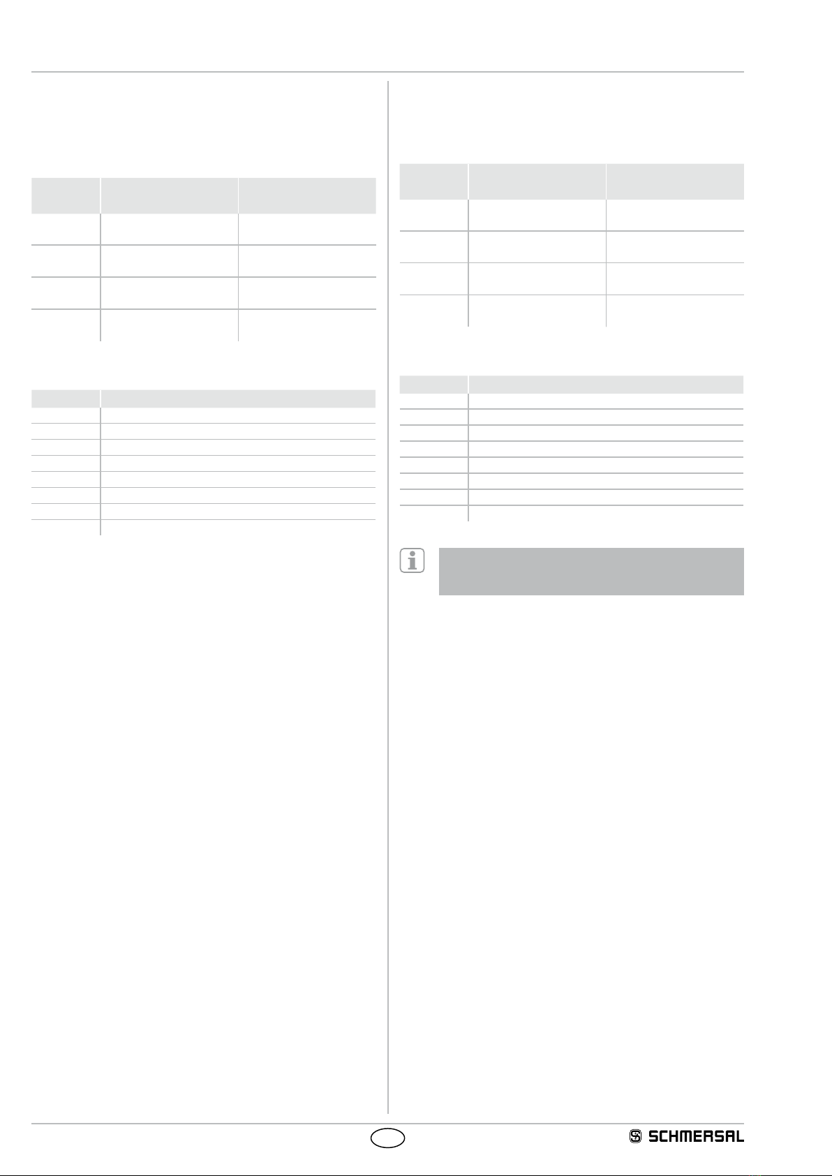
Position 3:
Illuminated pushbutton, indicator lights, pushbutton and
mushroom pushbutton
LT.., LM.., DT.., PT..
• Pushbutton function NO contact Response bit 3 = 1
NC contact Response bit 4 = 0
• Indicator lights LED Query bit 4
Maintained selector switch / spring-return selector switch,
2 positions:
WS2., WT2., SWS20, SWT20
1
0
• Position 0 NO contact Response bit 3 = 0
NC contact Response bit 4 = 1
• Position 1 NO contact Response bit 3 = 1
NC contact Response bit 4 = 0
Maintained selector switch / spring-return selector switch,
3 positions:
WS3., WT3., WTS3.
• Position 1 NO contact Response bit 3 = 0
0
1
2
NC contact Response bit 4 = 0
• Position 0 NO contact Response bit 3 = 0
NC contact Response bit 4 = 1
• Position 2 NO contact Response bit 3 = 1
NC contact Response bit 1 = 1
Position 4:
Illuminated pushbutton, indicator lights, pushbutton and
mushroom pushbutton
LT.., LM.., DT.., PT..
• Pushbutton function NO contact Response bit 5 = 1
• Indicator lights LED Query bit 5
5.5 Function of G24 indicator lamp
The G24 indicator lamp is controlled by the control system via the query
byte in the SD/FB protocol.
The bit assignment of the query byte is as follows:
• G24 Red LED Query bit 1
• G24 green LED Query bit 2