FireFlex TOTALPAC 2 PAR-3 User manual

Page 1 of 10
TOTALPAC2 Integrated Fire Protection System
PAR-3 Control Panel
FM-072G-0-05 C
Controls Section
1. Product Description
The Control Panel Section of the Self-Contained TOTALPAC2
unit is an add-on cabinet that is installed on the top of the trim
enclosure at the factory. This cabinet is fabricated of Gauge
14 steel, painted fire red with baked powder paint making it
rustproof, the same finish as the Trim Enclosure.
The Control Panel Section is provided with a locked stainless
steel door on the front giving access to the basic controls of
the Control Panel. Once opened, the cabinet door gives
access to the Contractor's Terminal Strip (refer to FIELD
WIRING DIAGRAM for additional details), the control panel
main board, emergency batteries and other related
equipment. Refer to Figures 1 and 2 for additional details.
2. Self-contained TOTALPAC2Unit (with Viking PAR-3 Model
B-2 Control Panel)
The Viking PAR-3 Model B-2 Control Panel is a supervised,
24 Volt, microprocessor-controlled release control panel.
The panel is designed to operate the electric release
solenoid, in the release piping of deluge or preaction
systems. The panel is available for use with either 120VAC-
60Hz or 220VAC-50Hz power supplies. The battery
compartment can hold two 12 volt batteries which are
charged by an internal battery charger. Batteries are
available to provide up to 90 hours of backup power during
AC power failure.
The PAR-3 panel can be used with a wide range of
compatible initiating devices such as pull stations, heat
detectors (including linear heat detectors), photo-electric and
ionization smoke detectors.
A dip switch 'Function Selector' allows field programming for
one of four possible input/output combinations, of which only
two are available and Listed for use with the TOTALPAC2
System: Single Hazard Two Zone and Single Hazard
Crossed Zone.
Changing the position of the dip switch will cause the panel to
go on trouble condition.
Warning ! Only the two configurations above are
Listed/Approved with the TOTALPAC2Unit. Changing the
position of the factory set dip switches may eliminate the
Fire Protection capabilities of the system and/or void
Listing/Approval and Warranty. Consult FireFlex Systems
before making any change !
In fire conditions when an initiating device circuit (or
predetermined combination of circuits) is energized, the panel
activates the release and signaling circuits according to the
'Function Selector' setting.
On the panel's display board, the appropriate Alarm, Trouble
and Supervisory LED's will flash until the event has been
acknowledged. After depressing the Tone or Alarm Silence
button, the LED will remain steadily illuminated until the panel
is reset.
3. Technical Data
Approvals:
The PAR-3 Control Panel when provided in the Control
Panel Section of the TOTALPAC2Unit forms an assembly
that is Underwriters Laboratories Inc. Listed (Model B2
for UL Listed systems & B-2C for ULC Listed systems)
and Factory Mutual Research <FM> Approved. Refer to
GENERAL SECTION for additional details.
Cabinet:
Vented enclosure:
1 ½" to 3" Dia. Units: 36" x 20" x 14"
4" & 6" Dia. Units: 46" x 24" x 14"
Environment:
Temperature: 32oF. (0oC) to 120oF (49oC)
Humidity: 85% Relative Humidity (non-condensing) at
86oF (30oC) maximum.
Recommended nominal room temperature: 60-80oF
(15-27oC).
AC Power:
PAR-3C: 120VAC, 50/60Hz, 1.2 amps.
Wire size: minimum #14 AWG with 600 Volt insulation.
PAR-3E: 220/240VAC, 50/60Hz, 0.6 amps.
Wire size: minimum #14 AWG with 600 Volt insulation.
Battery:
Lead Acid only
Maximum charging circuit: 27.6 V, 1.5A
Initiating Device (input) Circuits:
Four style B (Class B)/Style D (Class A) circuits factory
wired: Input 1: Detection Circuit
Input 2: Detection Circuit
Input 3: Water flow (Alarm pressure switch)
Input 4: Supervisory circuit.
Power limited circuitry
Normal operating voltage: 24VDC (ripple = 1.0V p-p)
Alarm current: 15mA minimum
Short circuit current: 40mA maximum
Maximum detector current in standby: 2mA (max) per
zone
Maximum loop resistance: 100 ohms
End-of-Line resistor: 4,7K-½Watt (provided) - Note:
leave EOL resistor provided on all unused circuits.
Detector loop current is sufficient to ensure operation of
one alarmed detector per zone.
Supervisory current: 5mA (including EOL resistor)
Heat Detectors: Detection circuits allow for installation
of any number of listed or approved normally open
thermal detectors.
Smoke Detectors: Refer to Device Compatibility
Document on our Web site for a list of compatible smoke
detectors, information concerning the maximum number
of smoke detectors allowed per zone, and standby
requirements for the smoke detector used.
Also, refer to appropriate Fire Protection Equipment
Approval Guides.

Page 2 of 10
TOTALPAC2 Integrated Fire Protection System
PAR-3 Control Panel
FM-072G-0-05 C
For supervised four-wire smoke detectors, connect the Power
Supervision Relay to the last detector base 24V screw
terminals. See ACCESSORIES.
Notification Appliance and Releasing Circuits:
Power limited circuitry
Two Style Y and two Style Y/Z circuits
Output 1: Alarm Bell (Style Y/Z)
Output 2: Waterflow or Trouble Horn (Style Y/Z)
Output 3: Releasing Circuit 1 (Style Y)
Output 4: Trouble Horn (Style Y)
Normal operating voltage: 24VDC
Total current available to all external devices: 2.25Amps
Maximum signaling current per circuit: 1.5Amps
Supervised circuitry
Maximum allowable voltage drop due to wiring: 2VDC
End-of-Line resistor: 4.7K-½Watt (provided) - Note: leave
EOL resistor provided on all unused circuits.
Refer to Device Compatibility Document on our Web site for a
list of compatible indicating appliances. Also, refer to
appropriate Fire Protection Equipment Approval Guides.
Alarm Relay:
Basic panel includes one non-silenceable Form-C dry alarm
contact rated 2 Amps at 30VDC and 0.5 amps at 20 VAC
(resistive).
Trouble Relay:
Basic panel includes one Form-C dry alarm contact rated at
2Amps at 30VDC and 0.5Amps at 30VAC (resistive).
Trouble relay will silence when trouble condition is cleared.
Zone Relay Module:
Model PAR-3 panel includes one Zone Relay Module (4XZM)
providing dry Form-C contacts controlled by each of the four
output circuits plus one general alarm and one panel/field
wiring trouble relay. See TABLE 2.
Power Outputs:
Four-wire Smoke Detector Power (resettable): Up to 200mA
total DC current available. Maximum ripple voltage: 1.0V p-p.
Non-resettable Power: Up to 200mA total (substracted from
four-wire smoke detector power) DC current available.
Maximum ripple voltage: 1.0V p-p.
RMS Regulated Power: Total current available for external
devices: 0.5Amp. (subtracted from the 2.25A available to
notification appliance circuits). Maximum ripple voltage:
100mV p-p.
4. Other features:
Front Panel Control Switches: (Refer to Figure 3).
Switch 1: Tone Silence
Switch 2: Alarm Silence
Tone Silence and Alarm Silence control switches can
be activated to acknowledge alarms. A second
"trouble" will resound the buzzer.
Switch 3: Alarm Activate
The Alarm Activate switch may be used to activate
signaling circuits and relays.
Switch 4: System reset.
The Reset switch clears any activated output
circuit. If alarm or trouble conditions exist when
the reset switch is pushed, they will re-activate
the panel.
Front Panel Zone Status LEDs:
When the panel is activated, zone status LEDs
illuminate, to indicate the status of Zone 1, Zone 2,
Alarm Pressure and Auxiliary Supervisory circuits.
Alarm (red) LEDs indicate activation of a detection
device.
Trouble (yellow) LED's indicate electrical circuit
failure such as short circuits and loose wiring.
Buzzer sounder
Alarm signals are latching.
Trouble signals are self restoring.
Alarm and Trouble resound.
Last event recall & Zone disable functions: Follow
procedure described in chapters 7 & 8.
Battery Fail and Earth Fault Supervision (see Figure 3
for location of LEDs).
Output circuits protected against false activation by a
two step command sequence.
Slide-in zone identification labels: Separate labels
included with PAR-3 Panel.
5. Accessories (order separately):
Batteries: Two batteries of the same AH rating are
required. Battery AH capacity shall be calculated with
the Battery Calculation Form provided in Chapter 9.
Battery sizes available are:
12V-7Amp-Hour – PN BATPS02407
12V-12Amp-Hour - PN BATPS02412
The 7AH Battery is normally sufficient to satisfy the 5
minutes of alarm after 24 hours requirement. For
FM's 90 Hours stand-by, the 12AH is normally used.
Batteries with larger AH capacity are also available
upon request.
Batteries plug-in connector is provided with the panel.
See BATTERIES TECHNICAL DATA to determine
which batteries meet standby battery requirements.
Wiring for 4-Wire type Smoke Detectors:
Depending on which Listed Smoke Detector is used
with the PAR-3 Model B-2 Control Panel, detector
maximum quantity is limited to between 15 and 30
per detection zone. For applications requiring more
detectors per detection zone, 4-Wire type smoke
detectors must be used. Refer to FIELD WIRING
DIAGRAM for additional details.
Optional Modules: One additional expansion connector is
available for installation of one of the following plug-in
modules:
LED Interface Module (4XLM): Provides the
interface required for connection of the PAR-3 Panel
to a Remote Status Annunciator (RZA-4X). Terminals

Page 3 of 10
TOTALPAC2 Integrated Fire Protection System
PAR-3 Control Panel
FM-072G-0-05 C
are factory connected to the TBR Terminal Strip as shown
in the CONTROL PANEL OPTIONS data sheet.
Should a remote annunciator be required with the TOTALPAC2
system (not to be confused with connection to the building's
existing Fire Alarm Control Panel which is achieved through
the standard dry output contacts), a Remote Annunciator
RZA-4X is available. This annunciator requires the
installation of the LED Interface Module 4XLM, which must
be factory installed. Refer to CONTROLS OPTIONS
datasheet for additional details.
Zone Relay Module (4XZM): Provides and additional 4
sets of Form "C" relays. Terminals are factory connected to
the TBC Terminal Strip as shown herewith:
TBC
1
2
4
3
7
8
6
5
10
12
11
9
NO
NC
C
NO
NC
C
NO
NC
C
NO
NC
C
SYSTEM ALARM
SYSTEM TROUBLE
WATER FLOW
SUPERVISORY
Activated by detection zone
OR water flow condition.
Activated by any abnormal electrical
Activated by the opening of the deluge or
Activated by a supervised valve in abnormal
position OR by low air pressure condition
condition of the system
flow control valve OR by alarm line verification
RATED 2 Amp. at 30V.dc / 0.5 Amp. at 30 V.ac (resistive)
NOTE: AUXILIARY DRY CONTACT RELAY OUTPUTS
USE ONLY WITH POWER LIMITED CIRCUITS.
FM-072Q-0-53 A.dwg
6. Installation:
Prior to installation of external devices and wiring, review and
observe all instructions provided herewith. Field wiring must
be according to FIELD WIRING DIAGRAM for the specific
mode of operation required.
.1 All wiring must be done in accordance with national and/or
Local codes for fire alarm systems. The Authority having
Jurisdiction may have additional requirements.
.2 Mount the cabinet in a clean, dry, vibration free area where
temperature and humidity conditions do not exceed
limitations indicated in TECHNICAL DATA above.
.3 Verify that all initiating devices (detectors, pull stations) and
indicating appliances (bells, horns and strobes) are
compatible with the PAR-3 Control Panel. Refer to Device
Compatibility Document on our Web site and appropriate
Fire Protection Equipment Approval Guides.
.4 Wire all alarm initiating devices sequentially for proper
supervision.
.5 Pull required conductors and drill knockouts as
required.
Note: The control panel motherboard is factory pre-wired
and programmed for the configuration selected at the
time of purchase. All field wiring should be terminated
on the terminals provided as shown on the FIELD
WIRING DIAGRAM. No connection needs nor should
be made directly to the panel motherboard as this would
void warranty and might prevent the normal operation of
the unit.
.6 Prior to connecting to the panel, verify continuity of all
circuitry. Check for, and correct any short circuits.
.7 Make electrical connections to TBA terminal strip for
the detection and alarm circuits according to the
FIELD WIRING DIAGRAM for the system used.
.a Where indicated on the FIELD WIRING DIAGRAM,
install the 4.7 kΩ½ Watt End of Line Resistor
(provided in panel) at the remote end of circuit.
.b On all un-used circuits, leave the 4.7 kΩ½ Watt
End of Line Resistor (provided in panel) in place.
.c Maintain polarity on alarm bell and trouble bell
circuits. Do not energize the panel until all
associated modules and associated cables have
been connected.
.8 Prior to energizing the panel:
.a Verify that dip switches controlling panel operation
are in the proper position for the system used.
Refer to TABLE 1 and FIELD WIRING DIAGRAM.
.b Verify that all modules are securely and properly
positioned on their pins. If a module is loose,
carefully align all pins and press firmly into position.
TABLE 1 – Basic Program
Mode #1
Single Hazard
Two Zone
Mode #2
Single Hazard
Crossed Zone
Switch 1
Switch 2
OFF
OFF
ON
OFF
Outputs 1 & 3 –
Activated by an alarm
on either Zone 1 or
Zone 2.
Output 2 – Activated by
a waterflow alarm on
Zone 3.
Output 4 – Activated by
a supervisory condition
on Zone 4.
Output 1 – Activated by
an alarm on either Zone
1 or Zone 2.
Output 2 – Activated by
a waterflow alarm on
Zone 3.
Output 3 – Activated by
alarms on both Zone 1
and Zone 2
Output 4 – Activated by
a supervisory condition
on Zone 4.
Zones 1 and 2 refer to Initiating Device Circuits 1 and 2.

Page 4 of 10
TOTALPAC2 Integrated Fire Protection System
PAR-3 Control Panel
FM-072G-0-05 C
Figure 1: Cabinet Door Assembly:
FM-072Q-0-20 A.dwg
Control section hinged door
(recessed hinges on top)
Releasing panel controls
access door (stainless steel)
Control Panel
annunciator window
Door Lock
(with key alike keys) Flush door handle
Figure 2: Typical Control Equipment Layout:
FM-072Q-0-19 C.dwg
NOTE: Front door assembly not shown for clarity.
Spare Sprinkler Heads
Storage Rack
(12 heads capacity)
'TBA' Field Wiring Terminals Strip
('TBC' & 'TBR' also when provided)
Typical Control Panel
Motherboard Placement
'TBB' Field Wiring Terminal Strip
for 120 / 220 Vac Power Feed
(under protective cover)
Air Compressor Isolating
Switch - rated 20 Amp.
(E15)
Placement of optional
Status Annunciator Module (MEA)
or Fail-Safe Timer (Elevators)
Emergency Batteries

Page 5 of 10
TOTALPAC2 Integrated Fire Protection System
PAR-3 Control Panel
FM-072G-0-05 C
Figure 3 – Detail of PAR-3 Model B-2 Panel Annunciator:
NOTE: Front door assembly not shown for clarity.
Spare Sprinkler Heads
Storage Rack
(12 heads capacity)
'TBA' - 'TBC' & 'TBR' Field Wiring
Terminals Strip
PAR-3 Control Panel
Motherboard Placement
Emergency Batteries
BATT EARTH MICRO FAIL
DIP Switches for
System Programming
J9
Troubleshooting LEDs (3)
Placement of optional
Status Annunciator Module (MEA)
or Fail-Safe Timer (Elevators) J9 Battery connector
AC Circuit Breaker
OPT-1
OPT-2
Refer to labels
description for detail.
FM-072Q-0-24C.dwg

Page 6 of 10
TOTALPAC2 Integrated Fire Protection System
PAR-3 Control Panel
FM-072G-0-05 C
6. System Status LEDs:
Alarm, Trouble and Supervisory LEDs will flash on and off
until the event(s) has been acknowledged (TONE or
ALARM SILENCE), at which point the LED will illuminate
steadily.
AC POWER: Green LED that illuminates steadily to
indicate presence of AC power.
SYSTEM ALARM: Red LED that flashes when an alarm
occurs.
SOLENOID OPERATED: Red LED that illuminates
steadily when the solenoid valve is activated.
SUPERVISORY: Yellow LED that flashes upon activation
of a supervisory device (main valve or Low air pressure).
SYSTEM TROUBLE: Yellow LED that flashes for any
trouble condition, including those associated with option
boards.
CIRCUIT TROUBLE: Yellow LED that flashes for trouble
conditions on output circuits.
ALARM SILENCED: Yellow LED that illuminates steadily
when the ALARM SILENCE switch has been pushed after
an alarm.
POWER TROUBLE: Yellow LED that flashes for low or
disconnected batteries and earth fault conditions.
BATT: Yellow LED that illuminates steadily on
motherboard when battery is low or not detected.
EARTH: Yellow LED that illuminates steadily on
motherboard during a ground fault condition.
MICRO FAIL: Yellow LED that illuminates on motherboard
when watchdog timer detects microprocessor failure.
Control Switches:
TONE SILENCE: Acknowledge alarms, troubles and
supervisory. The panel has alarm and trouble resound
with LED flash of new conditions.
The flashing trouble LED(s) illuminate steadily on TONE
SILENCE and the buzzer silences.
A Second trouble will resound the piezo. The piezo has
three sounds for alarm, trouble, and supervisory. Trouble
conditions are self restoring. Alarms and supervisories
latch and require RESET to clear.
ALARM SILENCE: Acknowledge for alarms and
supervisories. The ALARM SILENCE switch will silence
the local piezo, change any flashing alarm LEDs to steady,
and turn off the notification appliance circuits (not the
Releasing Circuits). The "ALARM SILENCED" LED will
illuminate. Alarm silence is a latching function and
requires a RESET to clear.
ALARM ACTIVATE: The ALARM ACTIVATE switch may
be used to activate Notification Appliance Circuits.
ALARM ACTIVATE also activates the System Alarm relay.
ALARM ACTIVATE is a latching function. Pressing
ALARM SILENCE silences the notification appliance
circuits and System Alarm Relay and lights the Alarm
Silenced LED. Pressing RESET returns the system to
normal.
SYSTEM RESET: The RESET switch breaks power to all
initiating circuits, 4-wire smoke power and option boards
and will clear any activated output circuits. If any alarm or
trouble still exists after reset, they will reactivate the panel.
Holding RESET down will perform a LAMP TEST function
and will activate the buzzer.
Zone Status LED(s):
The alarm and/or trouble LED(s) will flash until the
event(s) has been acknowledged (TONE or ALARM
SILENCE), at which point the LED(s) will illuminate
steadily. See detail below for the various configurations:
Double Interlocked
Preaction
Electric / PneuLectric
Deluge
ALARM LED
TROUBLE LED
ALARM LED
TROUBLE LED
ALARM LED
TROUBLE LED
(NOT USED)
TROUBLE LED
Double Interlocked
Preaction
Electric / Pneumatic
Double Interlocked
Preaction
Elevator Configuration
Single Interlocked
Preaction
DETECTION
ZONE 1
WATER FLOW
LOW AIR PRESS.
OR MAIN VALVE
WATER FLOW
LOW AIR PRESS.
OR MAIN VALVE
DETECTION
ALARM LOW AIR
PRESSURE
SYSTEM
PRESSURIZED
LOW AIR PRESS.
OR MAIN VALVE
DETECTION
ZONE 2
DETECTION
ZONE 1
DETECTION
ZONE 2
WATER FLOW
LOW AIR PRESS.
OR MAIN VALVE
DETECTION
ZONE 1
ELEVATOR AT
DESIGNATED
LOBBY
FAIL SAFE TIMER
DETECTION
ZONE 1
DETECTION
ZONE 2
WATER FLOW
MAIN VALVE
CONFIGURATION:

Page 7 of 10
TOTALPAC2 Integrated Fire Protection System
PAR-3 Control Panel
FM-072G-0-05 C
7. Zone Disable:
Disabling a detection or a supervisory zone will prevent
the internal audible signal in the control panel or any
output circuit from activating upon activation of a
detection device in this zone. All four entry zones can be
disabled.
Note: The system could become non-operational
depending on the zones being disabled. Furthermore,
the control panel must not be in alarm condition to effect
this function.
.1 To disable a zone, the following routine must be
followed:
.a Press the button identified TONE SILENCE and hold
it until all lamps go out.
.b While holding the button identified TONE SILENCE,
press the following buttons in this order: ALARM
SILENCE, ALARM ACTIVATE and then SYSTEM
RESET.
Note: Do not release the button identified TONE
SILENCE until the routine is completed.
.c The red lamp identified DETECTION or DETECTION
ZONE X will now begin to flash.
.d To disable that zone, press the button identified
SYSTEM RESET. A disabled zone is identified by
an illuminated yellow lamp on the zone.
Note: The button identified SYSTEM RESET operates
alternately; therefore press this button again to
reactivate the zone.
.2 To select the next zone, simply press the button
identified ALARM SILENCE. To select the previous
zone, press the button identified ALARM ACTIVATE.
.a When selection of the disabled zones is completed,
release the button identified TONE SILENCE.
.b The yellow lamp identified SYSTEM TROUBLE will
flash. Silence the audible signal by pressing the
button identified TONE SILENCE.
.3 To reactivate the zones previously disabled, repeat the
procedure to disable the zones. Pressing the button
identified SYSTEM RESET will deactivate the yellow
lamp of the selected zone, and thus reactivate the zones
that were disabled.
Note: Resetting the control panel will not reactivate the
disabled zones. However if the control panel is in alarm
condition and you wish to reactivate zones that were
previously disabled, then the control panel must be
reset.
8. Last Event recall:
This function allows the user to review the previous
condition of the control panel.
Note: The control panel must not be in alarm condition
when performing this function.
To recall the last event, the following routine must be
followed:
.1 Press the button identified TONE SILENCE and hold it
until all lamps go out.
.2 While holding the button identified TONE SILENCE,
press the following buttons in this order: SYSTEM
RESET, ALARM ACTIVATE and then ALARM
SILENCE.
.3 The lamps in the control panel will indicate the previous
condition since the last control panel reset.
.4 Release the button identified TONE SILENCE to return
to the normal operation mode.

Page 8 of 10
TOTALPAC2 Integrated Fire Protection System
PAR-3 Control Panel
FM-072G-0-05 C
9. BATTERIES TECHNICAL DATA:
Batteries are sealed construction, lead-acid rechargeable
that allow a trouble-free, safe operation in any position.
There is no need to add electrolyte as gases generated
during overcharge are recombined in a unique "Oxygen
Cycle".
No special handling precautions or shipping containers –
surface or air – are required due to the leak-proof
construction.
Under normal operating conditions four two five years of
dependable service can be expected in stand-by
applications or between 200 and 1000 charge/discharge
cycles depending upon depth of discharge.
The capacity of the batteries is expressed in amperes-hours
(AH) and is the total amount of electrical energy available
from a fully charged cell. The standard batteries provided
with the TOTALPAC2unit is 7AH capacity and should provide
enough power to provide the 5 minutes of alarm after 24
hours on stand-by required by UL and C-UL. 12AH batteries
are also available on option for the 90 Hrs standby period
requested by Factory Mutual (FM). The calculation chart
below shall be used to confirm batteries will be adequate.
.1 Standby Battery Requirements
The Standby Battery Current figure obtained in this table represents the amount of current that must be supplied by the
secondary power source (batteries) to sustain the control panel operation for one hour.
Control Panel (including a 4XZM Relay module) ..............................................................
with AC power lamp OFF, System trouble lamp and audible signal ON .096
If using an extra 4XZM Relay module ............................................................... add .008
If using a 4XLM / RZA-4X Driver / Annunciator combination ............................. add .019
Number
in use
Device current
(see Device
Compatibility Document
for data)
Total
current
Two-wire smoke detectors heads X =
Four-wire smoke detectors heads X =
End-of-line relays X =
Add Total current from the three lines above ª
If using 24Vdc RMS-Regulated Source (TBA-28/29) ............................ add load current
Total Standby Battery Current Amps
.2 Standby Period Required: Total Standby
Battery Current
Standby Time
(enter 24 or 90 hours
of operation)
amps X hours
Place result here for Standby AH ªAH
3. Alarm Battery Requirements +
Alarm AH (enter 0.25 for 5 minutes in alarm, or 0.5 for 10 minutes in alarm) AH
4. Total Ampere-Hour Calculations =
Total AH needed (add Standby AH & Alarm AH then multiply by 1.2 de-rating factor)AH
Select a battery with equal or greater AH rating than the Total AH obtained above. Batteries must be lead-acid type.
Notes:
1) Alarm AH assumes a maximum system draw of 3 amps in alarm for 5 minutes (0.25 AH) or for 10 minutes (0.5 AH).
2) NFPA 72-1993 Local Fire Alarm Systems standard requires 24 hours of standby power.
3) Factory Mutual Systems require 90 hours of standby power.
4) The battery charger in this panel will charge a maximum of 18 AH of batteries within 48 hours (7 AH minimum).

Page 9 of 10
TOTALPAC2 Integrated Fire Protection System
PAR-3 Control Panel
FM-072G-0-05 C
TROUBLE SHOOTING:
SYMPTOMS PROBLEM SOLUTION
Circuit trouble LED
ON Notification appliance circuit trouble
1. Check TBA for proper connections.
2. Remove all field wiring and install dummy
ELR at ourput circuit. Check for supervisory
voltage across it (normal –2,3V), if problem
persists, replace circuit board.
3. Remove dummy ELR, reconnect field wiring
and measure voltage across output; (tourble –
5V, short 0V).
4. Check for ELR at last device.
5. Check field wiring.
Any of the right
column yellow LEDs
flashing
Initiating zone open circuit trouble
1. Check TBA for proper connections.
2. Remove field wiring for zone in trouble and
install dummy ELR (4,7K for 24V; 2,2K for
12V). If problem persists, replace circuit
board.
Any of the right
column yellow LED
steady ON
Zone disable Check ZONE DISABLE section
Missing or
Disconnected Check battery connections
Battery trouble Batt
yellow LED ON Low or damaged
battery
1. Remove batteries, check voltage across
charger output (17 to 19V for 24V; 8-10V for
12V), otherwise, replace circuit board.
2. Reconnect batteries, measure battery
voltage at battery terminals. If voltage is less
than 85% of rated voltage, allow them to
charge for 48 hours.
3. If problem persists, replace batteries.
Ground fault trouble Earth yellow LED
ON
1. Remove field wiring from TBA. Install
dummy ELR (4,7K for 24V, 2,2K for 12V).
2. Remove both battery leads.
3. If trouble clears, connect one circuit at the
time to pinpoint the problem.
4. If trouble does not clear, replace circuit
board.
System Trouble LED
ON
Power trouble LED
ON
OPT1, OPT2 jumper cutted Install optional module or replace jumper if
module is not used.
Any of the right column red LEDs ON Short on initiating circuit wiring
Remove field wiring and install ELR. If trouble
clears, look for faulty or incorrectly wired
devices.
4XZM: Associated LED doesn't activate for
alarm, trouble or supervisory conditions. Optional module trouble
1. Make sure module is properly installed.
2. Move disable switch SW1 on 4XZM to the
left.
RZA-4X buzzer doesn't sound for alarm,
trouble or supervisory conditions. 4XLM
1. Make sure that the 4XLM module is
installed on J7 and J8.
2. Check field wiring.
All RZA-4X LEDs stay ON Power wasn't removed prior to
installation Press system reset.
AC Power LED ON
Micro Fail yellow LED ON Microprocessor damaged. Replace circuit board.
Loss of main power Check incoming power (TBB).
System trouble LED ON Damaged circuit breaker Replace circuit board.
AC power LED OFF
Micro Fail yellow LED ON Microprocessor damaged. Replace circuit board.

Page 10 of 10
TOTALPAC2 Integrated Fire Protection System
PAR-3 Control Panel
FM-072G-0-05 C
Table of contents
Popular Control Panel manuals by other brands

Helo
Helo RA 18 product manual
Siemens
Siemens Sinamics G130 Basic Operator Panel 20 operating instructions
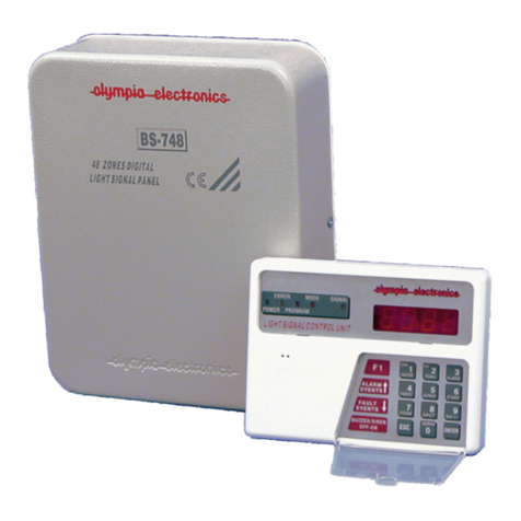
olympia electronics
olympia electronics BS-746 operating instructions
C & K Systems
C & K Systems Securit 802 Features
C & K Systems
C & K Systems System 2316E installation instructions
Spraying Systems
Spraying Systems AutoJet 1000+ quick start guide


