Fröling Lambdamat LM 1500 KOM User manual

Installation instructions
Lambdamat LM 1500 KOM
Translation of original German version of installation instructions for technicians.
Read and follow all instructions and safety instructions.
All errors and omissions excepted.
M2050222_en | Edition 18/08/2022

Table of contents
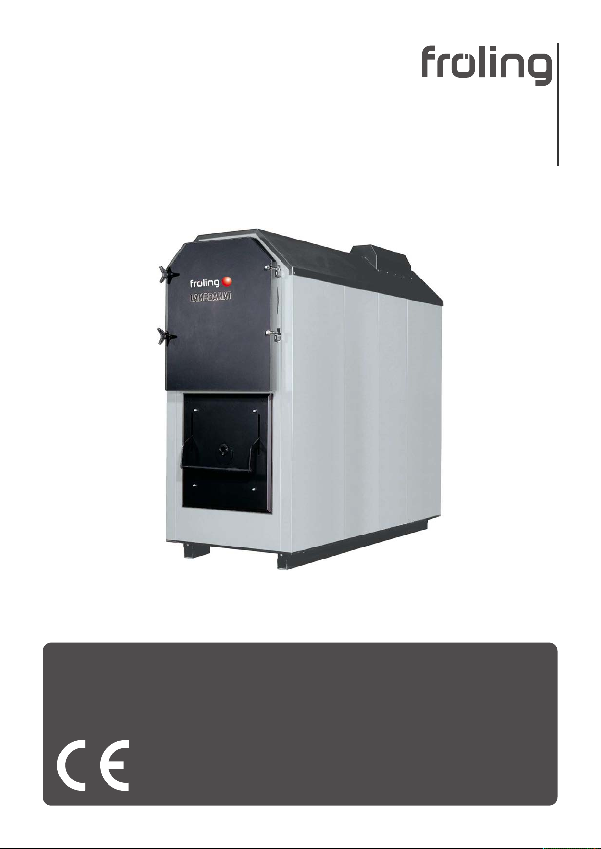
ii M2050222_en | Installation instructions Lambdamat LM 1500 KOM
1 General ......................................................................................................................................................... 4
2 Safety............................................................................................................................................................ 5
2.1 Hazard levels of warnings ..................................................................................................................... 5
2.2 Qualification of assembly staff .............................................................................................................. 6
2.3 Personal protective equipment for assembly staff ................................................................................ 6
3 Design Information...................................................................................................................................... 7
3.1 Overview of standards .......................................................................................................................... 7
3.1.1 General standards for heating systems ..................................................................................... 7
3.1.2 Standards for structural and safety devices............................................................................... 7
3.1.3 Standards for heating water....................................................................................................... 7
3.1.4 Regulations and standards for permitted fuels .......................................................................... 8
3.2 Installation and approval ....................................................................................................................... 8
3.3 Installation site ...................................................................................................................................... 8
3.4 Chimney connection/chimney system................................................................................................... 9
3.4.1 Connection line to the chimney.................................................................................................. 10
3.4.2 Measuring port ........................................................................................................................... 11
3.4.3 Draught limiter............................................................................................................................ 11
3.5 Domestic hot water ............................................................................................................................... 12
3.6 Pressure maintenance systems ............................................................................................................ 13
3.7 Storage tank.......................................................................................................................................... 14
3.8 Return lift............................................................................................................................................... 14
4 Technical information ................................................................................................................................. 15
4.1 Dimensions ........................................................................................................................................... 15
4.2 Components and connections............................................................................................................... 16
4.3 Technical specifications ........................................................................................................................ 17
5 Installation ................................................................................................................................................... 18
5.1 Transport............................................................................................................................................... 18
5.2 Temporary storage................................................................................................................................ 18
5.3 Positioning............................................................................................................................................. 18
5.3.1 Fit the ash duct for ash removal of the combustion chamber (only with Lambdamat 750)........ 19
5.3.2 Bolting together the combustion chamber and heat exchanger................................................. 19
5.4 Positioning at the installation site .......................................................................................................... 20
5.4.1 Moving the boiler in the boiler room........................................................................................... 20
5.4.2 Operating and maintenance areas of the equipment................................................................. 20
5.5 Laying firebricks in the combustion chamber ........................................................................................ 21
5.5.1 General ...................................................................................................................................... 21
5.5.2 Laying firebricks ......................................................................................................................... 22
5.6 Installing the boiler ................................................................................................................................ 23
5.6.1 General information ................................................................................................................... 23
5.6.2 Installing the stoker unit ............................................................................................................. 23
5.6.3 Installing the hydraulic stoker unit.............................................................................................. 24
5.6.4 Fitting the burn back slide valve................................................................................................. 25
5.6.5 Installing the air controllers ........................................................................................................ 26
5.6.6 Fitting the immersion sleeves for the thermal discharge valve and undergrate sensor............. 27
5.6.7 Fitting thermal insulation to the boiler ........................................................................................ 27
5.6.8 Fitting the insulation base frame ................................................................................................ 28
5.6.9 Fitting the side panels ................................................................................................................ 31
5.6.10 Fitting various covers ................................................................................................................. 34
5.6.11 Fitting the door contact switch ................................................................................................... 35
5.6.12 Fitting the combustion chamber ash removal unit (optional) ..................................................... 37
5.6.13 Installing the underpressure controller....................................................................................... 39

Table of contents
M2050222_en | Installation instructions Lambdamat LM 1500 KOM iii
5.6.14 Installing the combustion chamber overpressure and temperature sensors ............................. 39
5.6.15 Fitting the Lambda probe and various sensors.......................................................................... 40
5.6.16 Installing the servo-motors......................................................................................................... 41
5.6.17 Fitting the combustion air fan..................................................................................................... 42
5.6.18 Fitting the automatic ignition (optional) ...................................................................................... 43
5.6.19 Fitting an additional ignition for hydraulic stoker unit (optional) ................................................. 43
5.6.20 Fitting the compressed air cleaner (optional)............................................................................. 44
5.6.21 Fitting the ash sliding system (optional)..................................................................................... 45
5.6.22 Installing flue gas recirculation FGR (optional) .......................................................................... 46
5.7 Flue gas piping...................................................................................................................................... 50
5.8 Hydraulic connection............................................................................................................................. 51
5.8.1 Thermal discharge safety device connection............................................................................. 51
5.8.2 Thermal discharge safety device with zone valve...................................................................... 52
5.8.3 Connecting up the slide-on duct cooling .................................................................................... 54
5.9 Power connection and wiring ................................................................................................................ 55
5.9.1 Potential equalisation................................................................................................................. 55
5.10 Connecting the hydraulic cylinder ......................................................................................................... 55
6 Commissioning ........................................................................................................................................... 56
6.1 Before commissioning / configuring the boiler ...................................................................................... 56
6.1.1 Compressed air cleaner (optional)............................................................................................. 57
6.2 Initial startup.......................................................................................................................................... 57
6.2.1 Permitted fuels ........................................................................................................................... 57
6.2.2 Non-permitted fuels.................................................................................................................... 59
6.3 Heating up for the first time ................................................................................................................... 59
6.3.1 Screed drying............................................................................................................................. 60
7 Decommissioning ....................................................................................................................................... 61
7.1 Out of service for long periods .............................................................................................................. 61
7.2 Disassembly.......................................................................................................................................... 61
7.3 Disposal ................................................................................................................................................ 61

1 | General
4 M2050222_en | Installation instructions Lambdamat LM 1500 KOM
1 General
Thank you for choosing a quality product from Froling. The product features a state-of-
the-art design and conforms to all currently applicable standards and testing guidelines.
Please read and observe the documentation provided and always keep it close to the
system for reference. Observing the requirements and safety information in the
documentation makes a significant contribution to safe, appropriate, environmentally
friendly and economical operation of the system.
The constant further development of our products means that there may be minor
differences from the pictures and content. If you discover any errors, please let us know:
Subject to technical change.
Issuing a delivery
certificate The EC Declaration of Conformity is only valid in conjunction with a delivery certificate,
which has been filled in correctly and signed as part of the commissioning process. The
original document remains at the installation site. Commissioning installers or heating
engineers are requested to return a copy of the delivery certificate together with the
guarantee card to Froling. On commissioning by FROLING Customer Service the validity
of the delivery certificate will be noted on the customer service record.

Safety | 2
M2050222_en | Installation instructions Lambdamat LM 1500 KOM 5
2 Safety
2.1 Hazard levels of warnings
This documentation uses warnings with the following hazard levels to indicate direct
hazards and important safety instructions:
DANGER
The dangerous situation is imminent and if measures are not observed it will lead
to serious injury or death. You must follow the instructions!
WARNING
The dangerous situation may occur and if measures are not observed it will lead to
serious injury or death. Work with extreme care.
CAUTION
The dangerous situation may occur and if measures are not observed it will lead to
minor injuries.
NOTICE
The dangerous situation may occur and if measures are not observed it will lead to
damage to property or pollution.

2 | Safety
6 M2050222_en | Installation instructions Lambdamat LM 1500 KOM
2.2 Qualification of assembly staff
CAUTION
Assembly and installation by unqualified persons:
Risk of personal injury and damage to property
During assembly and installation:
rObserve the instructions and information in the manuals
rOnly allow appropriately qualified personnel to work on the system
Assembly, installation, initial startup and servicing must only be carried out by qualified
personnel:
▪ Heating technicians/building technicians
▪ Electrical installation technicians
▪ Froling customer services
The assembly staff must have read and understood the instructions in the documentation.
2.3 Personal protective equipment for assembly staff
You must ensure that staff have the protective equipment specified by accident
prevention regulations!
▪ During transport, erection and installation:
- wear suitable work wear
- wear protective gloves
- wear safety shoes (min. protection class S1P)

Design Information | 3
M2050222_en | Installation instructions Lambdamat LM 1500 KOM 7
3 Design Information
3.1 Overview of standards
Perform installation and commissioning of the system in accordance with the local fire
and building regulations. Unless contrary to other national regulations, the latest versions
of the following standards and guidelines apply:
3.1.1 General standards for heating systems
EN 303-5 Boilers for solid fuels, manually and automatically fed combustion
systems, nominal heat output up to 500 kW
EN 12828 Heating systems in buildings - design of water-based heating
systems
EN 13384-1 Chimneys - Thermal and fluid dynamic calculation methods
Part 1: Chimneys serving one appliance
ÖNORM H 5151 Planning of central hot water heating systems with or without hot
water preparation
ÖNORM M 7510-1 Guidelines for checking central heating systems
Part 1: General requirements and one-off inspections
ÖNORM M 7510-4 Guidelines for checking central heating systems
Part 4: Simple check for heating plants for solid fuels
3.1.2 Standards for structural and safety devices
ÖNORM H 5170 Heating installation - Requirements for construction and safety
engineering, as well as fire prevention and environmental protection
TRVB H 118 Technical directives for fire protection/prevention (Austria)
3.1.3 Standards for heating water
ÖNORM H 5195-1 Prevention of damage by corrosion and scale formation in closed
warm water heating systems at operating temperatures up to 100°C
(Austria).
VDI 2035 Prevention of damage hot water heating systems (Germany)
SWKI BT 102-01 Water quality for heating, steam, cooling and air conditioning
systems (Switzerland)
UNI 8065 Technical standard regulating hot water preparation.
DM 26.06.2015 (Ministerial Decree specifying the minimum
requirements)
Follow the instructions of this standard and any related updates.
(Italy)

3 | Design Information
8 M2050222_en | Installation instructions Lambdamat LM 1500 KOM
3.1.4 Regulations and standards for permitted fuels
1. BImSchV First Order of the German Federal Government for the
implementation of the Federal Law on Emission Protection
(Ordinance on Small and Medium Combustion Plants) in the version
published on 26 January 2010,
BGBl. JG 2010 Part I No. 4.
EN ISO 17225-2 Solid bio-fuel - Fuel specifications and classes
Part 2: Wood pellets for use in industrial and domestic systems
EN ISO 17225-4 Solid bio-fuel - Fuel specifications and classes
Part 4: Wood chips for non-industrial use
3.2 Installation and approval
The boiler should be operated in a closed heating system. The following standards
govern the installation:
Note on standards EN 12828 - Heating Systems in Buildings
IMPORTANT: Every heating system must be officially approved.
The appropriate supervisory authority (inspection agency) must always be informed when
installing or modifying a heating system, and authorisation must be obtained from the
building authorities:
Austria: report to the construction authorities of the community or magistrate
Germany: report new installations to an approved chimney sweep / the building
authorities.
3.3 Installation site
Requirements for the load bearing substrate:
▪ Flat, clean and dry
▪ Non-combustible and with sufficient load-bearing capacity
Conditions at the installation site:
▪ Frost-free
▪ Sufficiently well lit
▪ Free of explosive atmospheres such as flammable substances, hydrogen halides,
cleaning agents and consumables
▪ Installation at altitude higher than 2000 metres above sea level only after consultation
with the manufacturer
▪ The system must be protected against gnawing and nesting by animals (such as
rodents)
▪ No flammable materials in proximity to the system

Design Information | 3
M2050222_en | Installation instructions Lambdamat LM 1500 KOM 9
3.4 Chimney connection/chimney system
1
2
3
4
5
1Connection line to the chimney
2Measuring port
3Draught limiter
4Explosion flap (for automatic boilers)
5Thermal insulation
NOTICE!The chimney must be authorised by a smoke trap sweeper or chimney
sweep.
The entire flue gas system (chimney and connection) must be laid out as per ÖNORM /
DIN EN 13384-1 or ÖNORM M 7515 / DIN 4705-1.
The flue gas temperatures (for clean systems) and additional flue gas values can be
found in the table in the technical data.
Local regulations and other statutory regulations are also applicable.
EN 303-5 specifies that the entire flue gas system must be designed to prevent, wherever
possible, damage caused by seepage, insufficient feed pressure and condensation.
Please note within the permissible operating range of the boiler flue gas temperatures
lower than 160K above room temperature may occur.

3 | Design Information
10 M2050222_en | Installation instructions Lambdamat LM 1500 KOM
3.4.1 Connection line to the chimney
Requirements for the connection line:
▪ this should be as short as possible and follow an upward incline to the chimney (30 -
45° recommended)
▪ thermally insulated
MFeuV1) (Germany) EN 15287-1 and EN 15287-2
400
100
[mm]
D
20
23
3 x D
[mm]
D
(min. 375)
1,5 x D
(min. 200)
2
4
1. Observe the fire regulations of the respective federal state
2. Component made of flammable material
3. Nonflammable insulating material
4. Radiation shield with rear ventilation
Minimum distance from flammable substances as per MFeuV1) (Germany):
▪ 400 mm excluding thermal insulation
▪ 100 mm if at least 20 mm thermal insulation is installed
Minimum distance from flammable materials as per EN 15287-1 and EN 15287-2:
▪ 3 x nominal diameter of connection line, but at least 375 mm (NM)
▪ 1.5 x nominal diameter of connection line for radiation shield with rear ventilation, but
at least 200 mm (NM)
NOTICE!The minimum distances must be observed in accordance with the
standards and guidelines applicable in the region

Design Information | 3
M2050222_en | Installation instructions Lambdamat LM 1500 KOM 11
3.4.2 Measuring port
For emissions measurement on the system, a suitable measuring port must be installed
in the connection line between the boiler and chimney system.
2 x D
D
D
M
Upstream of the measuring port (M) there should be a straight run-in section with a length
about twice the diameter (D) of the connection line. Downstream of the measuring port
(M) there should be a straight run-out section with a length about the diameter (D) of the
connection line. The measuring port must remain closed whenever the system is in
operation.
The diameter of the measuring probe used by Froling customer service is 14 mm. To
avoid measuring errors due to the ingress of false air, the diameter of the measuring port
must not exceed 21mm.
3.4.3 Draught limiter
We generally recommend the installation of a draught limiter. A draught limiter must be
installed if the maximum permissible feed pressure as given in the boiler data for planning
the flue gas system is exceeded.
NOTICE!Install the draught limiter directly under the mouth of the flue line, as the
pressure is constantly low at this point.

3 | Design Information
12 M2050222_en | Installation instructions Lambdamat LM 1500 KOM
3.5 Domestic hot water
Unless contrary to other national regulations, the latest versions of the following
standards and guidelines apply:
Austria:
Germany:
ÖNORM H 5195
VDI 2035
Switzerland:
Italy:
SWKI BT 102-01
UNI 8065
Observe the standards and also follow the recommendations below:
rAim for a pH value of between 8.2 and 10.0. If the central heating water comes into
contact with aluminium, the pH value must be between 8.2 and 9.0
rUse prepared water which complies with the standards cited above for filling and
make-up water
rAvoid leaks and use a closed heating system to maintain water quality during
operation
rWhen filling with make-up water, always bleed the filling hose before connecting, in
order to prevent air from entering the system
rThe heating water must be clear and free from substances that lead to sediments.
rWith regard to corrosion protection, the use of fully demineralised filling and make-up
water with an electrical conductivity of up to 100 µS/cm is recommended in
accordance with EN 14868
Advantages of low-salt or fully demineralised water:
▪ Complies with the applicable standards
▪ Less of a drop in output due to reduced limescale build-up
▪ Less corrosion due to fewer aggressive substances
▪ Long-term cost savings thanks to improved energy efficiency
Filling and make-up water as well as heating water in accordance with VDI 2035:
Total heat output in kW Total earth alkalis in mol/m³ (total hardness in °dH)
Specific system volume in l/kW heat output1)
≤ 20 20 to ≤40 > 40
≤ 50
specific water content
heat generator ≥ 0.3 l/kW2)
none ≤ 3.0 (16.8) < 0.05 (0.3)
≤ 50
specific water content
heat generator < 0.3 l/kW2)
(e.g. circulation water heater) and
systems with electric heating
elements
≤ 3.0 (16.8) ≤ 1.5 (8.4)
> 50 to ≤ 200 ≤ 2.0 (11.2) ≤ 1.0 (5.6)
> 200 to ≤ 600 ≤ 1.5 (8.4) < 0.05 (0.3)
> 600 < 0.05 (0.3)
1. For calculating the specific system volume, the smallest individual heating capacity is to be used for systems with several heat generators.
2. In systems with several heat generators with different specific water contents, the smallest specific water content is decisive in each case.

Design Information | 3
M2050222_en | Installation instructions Lambdamat LM 1500 KOM 13
Additional requirements for Switzerland
The filling and make-up water must be demineralised (fully purified)
▪ The water must not contain any ingredients that could settle and accumulate in the system
▪ This makes the water non-electroconductive, which prevents corrosion
▪ It also removes all the neutral salts such as chloride, sulphate and nitrate which can weaken
corrosive materials in certain conditions
If some of the system water is lost, e.g. during repairs, the make-up water must also be
demineralised. It is not enough to soften the water. The heating system must be professionally
cleaned and rinsed before filling the units.
Inspection:
▪ After eight weeks, the pH value of the water must be between 8.2 and 10.0. If the central
heating water comes into contact with aluminium, the pH value must be between 8.0 and 8.5
▪ Yearly. Values must be recorded by the owner
3.6 Pressure maintenance systems
Pressure maintenance systems in hot-water heating systems keep the required pressure
within predefined limits and balance out volume variations caused by changes in the hot-
water temperature. Two main systems are used:
Compressor-controlled pressure maintenance
In compressor-controlled pressure maintenance units, a variable air cushion in the
expansion tank is responsible for volume compensation and pressure maintenance. If the
pressure is too low, the compressor pumps air into the tank. If the pressure is too high, air
is released by means of a solenoid valve. The systems are built solely with closed-
diaphragm expansion tanks to prevent the damaging introduction of oxygen into the
heating water.
Pump-controlled pressure maintenance
A pump-controlled pressure maintenance unit essentially consists of a pressure-
maintenance pump, relief valve and an unpressurised receiving tank. The valve releases
hot water into the receiving tank if the pressure is too high. If the pressure drops below a
preset value, the pump draws water from the receiving tank and feeds it back into the
heating system. Pump-controlled pressure maintenance systems with open expansion
tanks (e.g. without a diaphragm) introduce ambient oxygen via the surface of the water,
exposing the connected system components to the risk of corrosion. These systems offer
no oxygen removal for the purposes of corrosion control as required by VDI 2035 and in
the interests of corrosion protection should not be used.

3 | Design Information
14 M2050222_en | Installation instructions Lambdamat LM 1500 KOM
3.7 Storage tank
NOTICE
In principle it is not necessary to use a storage tank for the system to run smoothly.
However we recommend that you use the system with a storage tank, as this ensures a
continuous supply of fuel in the ideal output range of the boiler.
For the correct dimensions of the storage tank and the line insulation (in accordance with
ÖNORM M 7510 or guideline UZ37) please consult your installer or Fröling.
Additional requirements for Switzerland in accordance with LRV Appendix 3, section 523
Automatic boilers with a rated thermal output ≤ 500 kW must be equipped with a heat
accumulator of a volume of at least 25 litres per kW rated thermal output.
3.8 Return lift
If the hot water return temperature is below the minimum return temperature, some of the
hot water outfeed will be mixed in.
NOTICE
Risk of dropping below dew point/condensation formation if operated without return
temperature control.
Condensation water forms an aggressive condensate when combined with
combustion residue, leading to damage to the boiler.
Take the following precautions:
rRegulations stipulate the use of a return temperature control.
ÄThe minimum return temperature is 60 °C. We recommend fitting some kind of
control device (e.g. thermometer).

Technical information | 4
M2050222_en | Installation instructions Lambdamat LM 1500 KOM 15
4 Technical information
4.1 Dimensions
B3
B1
H4 H3
H2
H1
L2 L3
L1
L2
L4
B2 B4
B5
B6
H4
L5
Dimensi
on
Description Unit LM 1500
H1 Height, flow/return connection mm 4660
H2 Height, boiler 4585
H3 Height, flue pipe connection 4200
H4 Height of stoker connection incl. burn back protection
system
(wood chips BBF 300)
1500
Height of hydraulic slide-on duct connection 1,095
B1 Total width of boiler 3,960
B2 Width of blower fan 750
B3 Width, boiler 1840
B4 Width of ash container (optional) 1370
B5Width of compressed air cleaner (optional) 605
B6 Width of flue gas recirculation (optional) 1075
L1 Length of boiler incl. stoker 5,655
Length of boiler incl. hydraulic slide-on duct 7,075
L2 Length, stoker incl. gears 1290
Length of hydraulic slide-on duct 2715
L3 Length of boiler 4,065
L4 Length of compressed air cleaner (optional) 295
L5 Length, flue gas collection box 500

4 | Technical information
16 M2050222_en | Installation instructions Lambdamat LM 1500 KOM
4.2 Components and connections
E
I
D
GFHBAC C C
Item Description LM 1500
ABoiler flow connection DN150 / PN 6
BBoiler return connection DN150 / PN 6
CConnection to safety heat exchanger (2) 1” ET
DFlue gas pipe connection 500 mm
EFGR (flue gas recirculation) connection 300 mm
FBroadband probe connection -
GFlue gas temperature sensor connection -
HSafety valve connection (provided by the customer) DN80 / PN 6
IDrainage connection 2“ IT

Technical information | 4
M2050222_en | Installation instructions Lambdamat LM 1500 KOM 17
4.3 Technical specifications
Description LM 1500
Nominal heat output kW 1500
Output range 450 - 1500
Nominal fuel heating efficiency with wood chips 1667
Efficiency at nominal load / partial load % > 90.0
Quantity of wood chips required at nominal load kg/h 490
Electrical connection 400V / 50Hz
Electric fuses1) A as per circuit diagram
Electrical power consumption W as per circuit diagram
Dimensions required for combustion chamber
installation (LxWxH)
mm 4780 x 1830 x 2700
Dimensions required for heat exchanger installation
(LxWxH)
3980 x 1850 x 1950
Weight – combustion chamber kg 7600
Weight - heat exchanger 8,200
Weight – fireclay 7500
Total weight excl. fittings 23300
Heat exchanger water capacity l 4,240
Water pressure drop (ΔT = 20 K) mbar 63
Flow rate (ΔT = 10 K) m³/h 129.3
Flow rate (ΔT = 15 K) 86.2
Flow rate (ΔT = 20 K) 64.7
Minimum ventilation opening as per ÖNORM H 5170 cm² 3338
Minimum boiler return temperature °C 60
Maximum permitted operating temperature 952)
Maximum permitted working over-pressure bar 6
Permitted fuel acc. to EN ISO 172253) Part 4: Wood chips class A2 / P16S-P45S
Airborne sound level dB(A) <70
1. Electric fuses and power consumption vary depending on design and features
2. > 95 °C upon request
3. Detailed information on the fuel can be found in the operating instructions in the section entitled “Permitted fuels”
Boiler data for planning the flue gas system
Description LM 1500
Flue gas temperature at nominal load / partial load °C 220 / 160
Draught requirement at ID fan outlet at
nominal load / partial load
Pa 5 / 2
mbar 0.05 / 0.02
CO2- volume concentration at nominal load / partial
load
% 10.3 / 10.3
Flue gas mass flow with wood chip W30, 12% O21) m3/h (kg/
h)
8,838 (6,240)
Flue gas mass flow with wood chips W30, 9% O26,285 (4,428)
Recommended maximum chimney draught Pa 60
mbar 0.6
1. use the maximum attainable oxygen content for chimney design

5 | Installation
18 M2050222_en | Installation instructions Lambdamat LM 1500 KOM
5 Installation
WARNING
Risk of falling when working at a height
Therefore:
rImplement appropriate measures in accordance with the applicable national industrial
safety guidelines to protect against the risk of falling (e.g. ladders, platforms, etc.)
5.1 Transport
NOTICE
Possibility of damage to components if handled incorrectly
rFollow the transport instructions on the packaging
rTransport components with care to avoid damage
rProtect components against damp
rUnloading, positioning and installation should only be performed by trained
professionals! Staff must be trained in techniques for moving heavy loads (correct
tools and lifting equipment, hooking and slinging points, etc.)
5.2 Temporary storage
If the system is to be assembled at a later stage:
rStore components at a protected location, which is dry and free from dust
ÄDamp conditions and frost can damage components, particularly electric ones!
5.3 Positioning
rSecure cable winch or similar lifting device to the attachment points on the heat
exchanger (A) and the combustion chamber (B) and position the components.

Installation | 5
M2050222_en | Installation instructions Lambdamat LM 1500 KOM 19
5.3.1 Fit the ash duct for ash removal of the combustion chamber (only with
Lambdamat 750).
NOTICE!If ash is to be removed from the boiler via an ash screw, a base must be
provided by the customer beneath the boiler.
Ü "Dimensions" [}15]
If an ash screw (optional) is provided for removing ash from the combustion chamber, the
ash duct should be fitted as follows when the combustion chamber is being positioned.
rFit the ash duct to the underside of the combustion chamber.
5.3.2 Bolting together the combustion chamber and heat exchanger
rPosition the heat exchanger on the centre of the combustion chamber and secure to
the combustion chamber with 4x screws and nuts.
ÄAlso screw on the earthing wire (supplied) with the toothed washer as potential
equalisation.

5 | Installation
20 M2050222_en | Installation instructions Lambdamat LM 1500 KOM
5.4 Positioning at the installation site
5.4.1 Moving the boiler in the boiler room
rPosition a lifting device with a suitable load-bearing capacity at the base frame.
rLift and transport to the intended position in the installation room.
ÄObserve the minimum distances in the boiler room.
5.4.2 Operating and maintenance areas of the equipment
▪ The system should generally be set up so that it is accessible from all sides to allow
quick and easy maintenance!
▪ Regional regulations regarding necessary maintenance areas for inspecting the
chimney should be observed in addition to the specified distances!
▪ Observe the applicable standards and regulations when setting up the system!
▪ Comply with additional standards for noise protection!
(ÖNORM H 5190 - Noise protection measures)
D1
B1
B2
A1
C1
E1
A1 3,650 mm
B1 1,400 mm
B2 1,800 mm
(2,100 mm for dismantling the ash screw for maintenance tasks)
C1 Stoker: 2,240 mm
hydraulic slide-on duct: 3,000 mm
D1 900 mm
E1 5,100 mm
Table of contents
Other Fröling Heating System manuals
Popular Heating System manuals by other brands

Pichler
Pichler LG 250 A Operating and installation instructions

BLAUBERG Ventilatoren
BLAUBERG Ventilatoren KOMFORT Roto EC S6K 200 user manual

Viessmann
Viessmann Vitotronic 200 Series Operating Instructions for the System User

UFESA
UFESA Multiaqua Series operating instructions

Hydro-Hot
Hydro-Hot HHE-200-09E owner's manual

Baxi
Baxi LUNA SAT Installation and operating manual

EBECO
EBECO Snowmelt Assembly instructions

Okofen
Okofen PE 08 operating manual

oventrop
oventrop Flypass 4TZ Installation and operating instructions

Valsir
Valsir ARIA EVO V Series manual

nVent RAYCHEM
nVent RAYCHEM Mat installation instructions

GammaSwiss
GammaSwiss RoofMate Assembly, installation and operation instructions