Fröling PE1e User manual

Installation instructions
Electrostatic particle separator
PE1e Pellet 45-60
Translation of original German version of installation instructions for technicians.
Read and follow all instructions and safety instructions.
All errors and omissions excepted.
M2420223_en | Edition 13/02/2023

1 | General
2 M2420223_en | Installation instructions Electrostatic particle separator
1 General
The pellet boiler PE1e Pellet 45-60 can be equipped with an electrostatic particle
separator.
rSwitch off the boiler and allow it to cool down
rSwitch off the power supply to the boiler
CAUTION
Assembly and installation by unqualified persons:
Risk of personal injury and damage to property
During assembly and installation:
rObserve the instructions and information in the manuals
rOnly allow appropriately qualified personnel to work on the system
rIn addition to these instructions, please also note the warnings in the operating/
installation manual for the boiler.
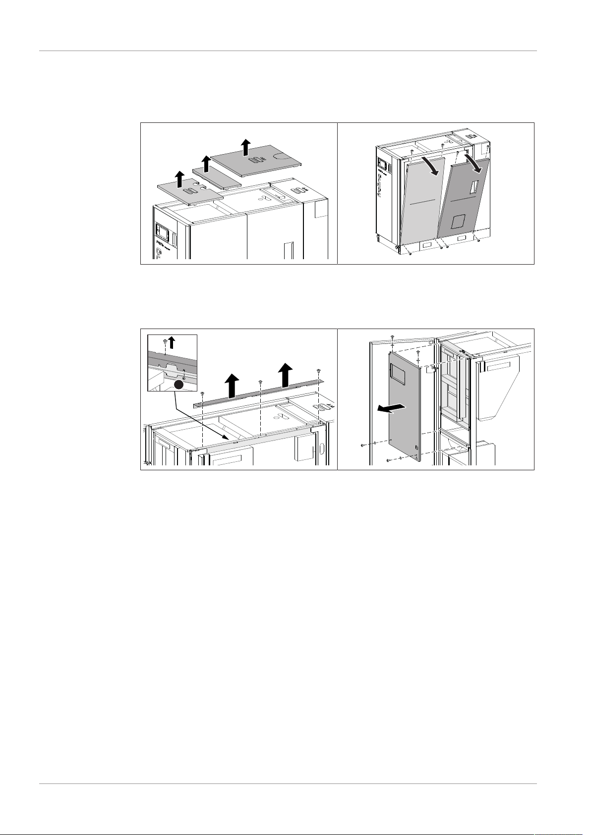
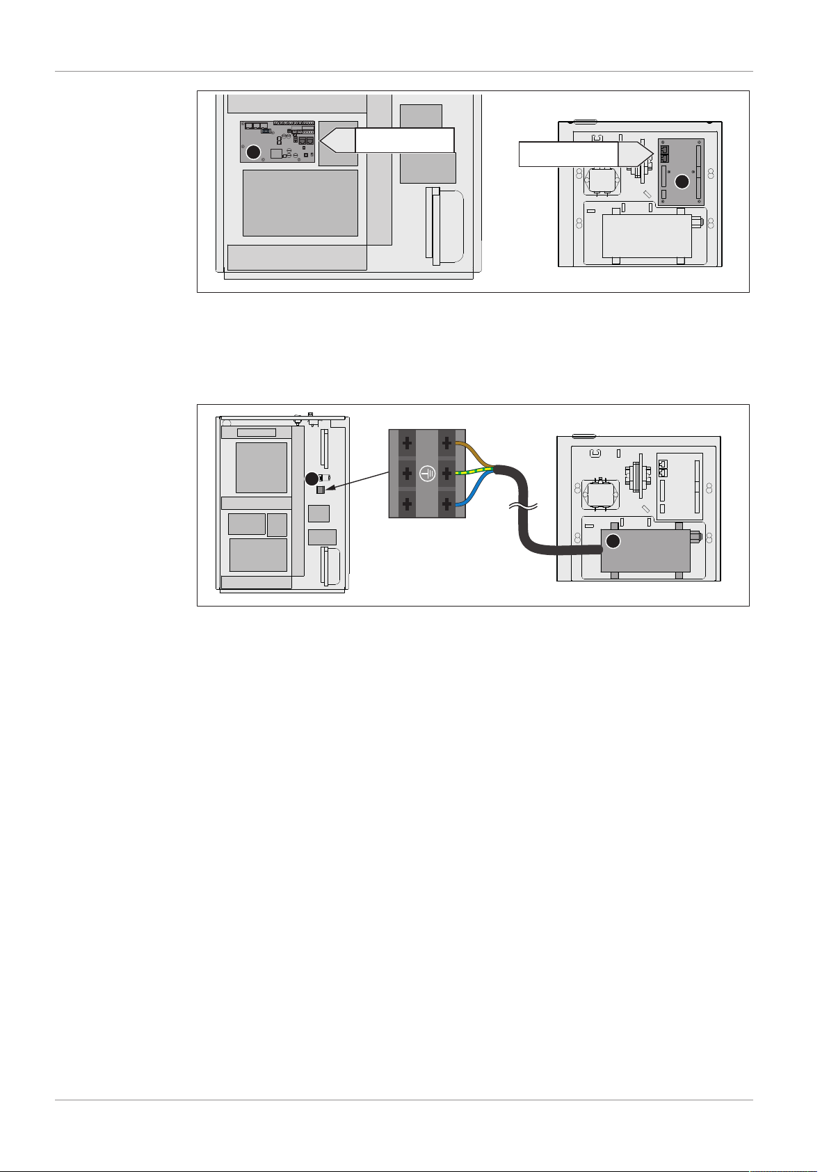
The following assembly steps illustrate the retrofitting of the electrostatic particle
separator on a PE1e Pellet condensing boiler 45-60. Retrofitting a PE1e Pellet 45-60
pellet boiler is analogous.
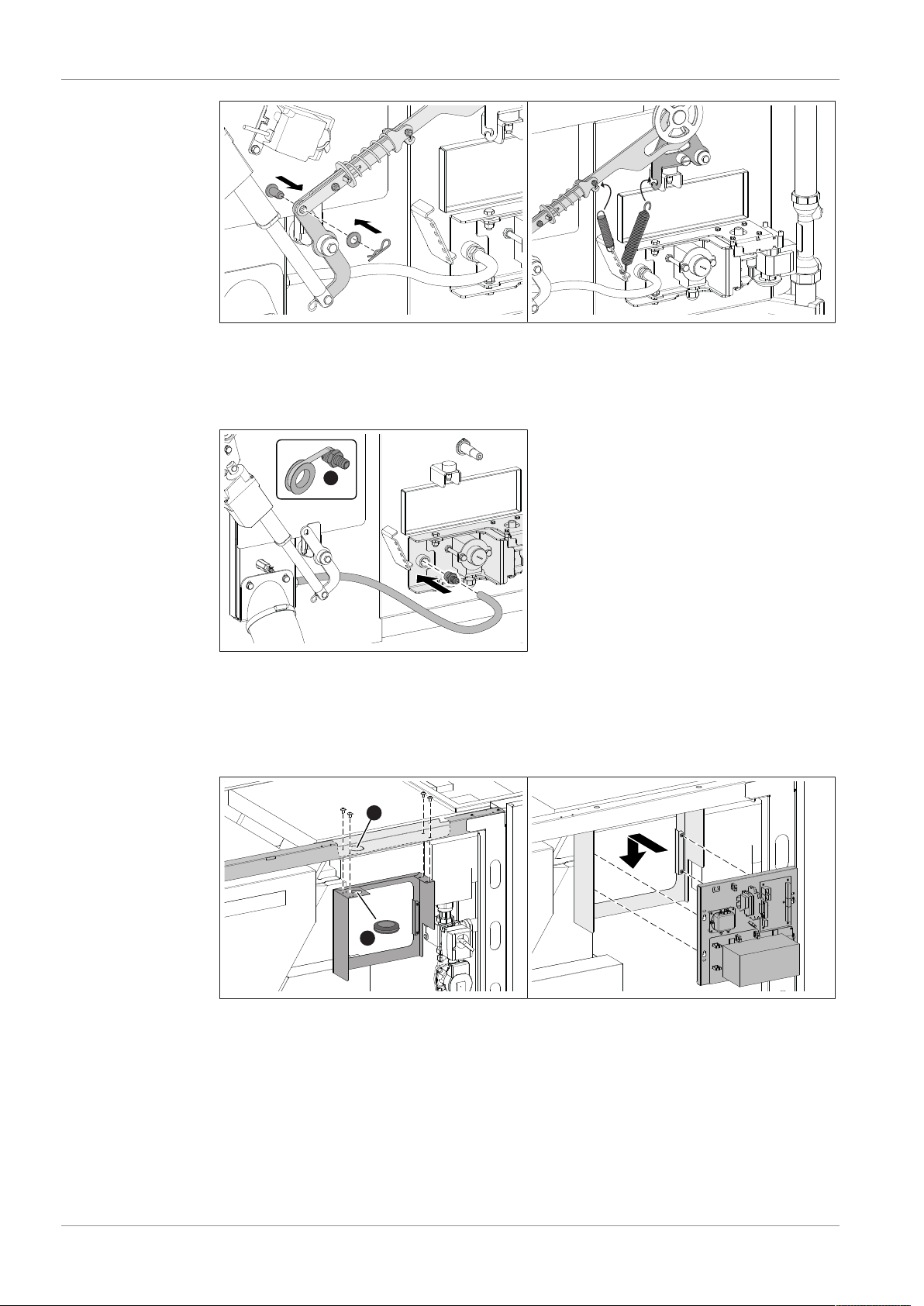
Some assembly steps illustrate additional activities for boilers with room air-independent
operation.
Boilers without room air-independent
operation
Boilers with room air-independent operation

General | 1
M2420223_en | Installation instructions Electrostatic particle separator 3
1.1 Materials supplied
A B C D
E F G H
AControl unit ECable grommet
WFrame for distributor box FHigh-voltage cable
CHook in plates GElectrode unit
DBulkhead plate HScrew-in plate

2 | Assembly
4 M2420223_en | Installation instructions Electrostatic particle separator
2 Assembly
2.1 Boiler preparation
rRemove the cover on the upper side of the boiler
rRemoving the side panels
- 4x lens-head screws M6 x 12 per side panel
A
rRemove the cover of the cable duct
- loosen the 3 lens-head screws M4 x 8 on the top
- loosen the 4 lens-head screws M4 x 8 on the inside (A)
rOpen the insulated door and remove the controller cover behind
- 4x lens-head screws M4 x 8 incl. contact washer

Assembly | 2
M2420223_en | Installation instructions Electrostatic particle separator 5
A
rUnhook tension springs on the connecting rod of the WOS
ÄTIP: Mark hook-in positions
rLift the driver lever in the upper area (A) and remove the pin as well as spring cotter
rDismantle the drive lever and remove the key from WOS shaft
- 1 hexagonal screw M8 x 16
rRemove the heat exchanger cover
- 4x hexagonal screws M8 x 45

2 | Assembly
6 M2420223_en | Installation instructions Electrostatic particle separator
2.2 Particle separator assembly
A
B
A
rInstall screw-in plate on the rear connection plate
- 2x hexagonal screws M6 x 12
rRelease the pin clasp (A) on the connection plate
rHook the hook-in plate into both pins and secure with the pin clasp (A)
ÄMake sure that the tilting (B) points in the direction of the back of the boiler
A
B
rInstall the bulkhead plate on the tabs underneath the square shaft
- 2x round-head screws M8 x 20
rRelease the pin clasp (A) on the connection plate
rHook the hook-in plate into both pins and secure with the pin clasp (A)
ÄMake sure that the tilting (B) points in the direction of the back of the boiler

Assembly | 2
M2420223_en | Installation instructions Electrostatic particle separator 7
rInstall the side heat exchanger cover on the body of the boiler
- 4x hexagonal screws M8 x 45
rRemove bottom cover
- 4x hexagonal screws M8 x 30
A
rRemove the top cover
- 4x hexagonal screws M8 x 30
rInsert the electrode unit into the bottom opening and install
- 4x hexagonal screws M8 x 30
ÄIn so doing, position the electrode centrally between the linking plates by tightening
the hexagonal screws (A)
rInstall top cover
- 4x hexagonal screws M8 x 30
rInsert key into groove of the WOS shaft and install the drive lever
-1x hexagonal screw M8 x 16

2 | Assembly
8 M2420223_en | Installation instructions Electrostatic particle separator
rSecure driver lever with pin and spring cotter
rHook tension springs on the connecting rod of the WOS
ÄUse the previously marked holes
A
For room air-independent operation:
rSeal the hose support (A) thread with Teflon and screw into the electrode unit in the
sleeve
rSlide the silicone hose onto the hose support
A
B
rRemove round perforation (A) on the upper frame and remove the burrs using a half-
round file
rInsert the cable grommet (B) into the round cut-out on the frame.
rInstall the frame on the top support
- 4x lens-head screws M4 x 8
rHook the control unit on the screw heads and secure it

Assembly | 2
M2420223_en | Installation instructions Electrostatic particle separator 9
2.3 Electrical connection
rRun the high voltage cable from the HV module to the electrode unit
ÄUse cable ties to attach the high voltage cable to the side frame
rInsert the connector into the electrode unit and tighten the connection
ÄThe connector must click noticeably into place
rRun the cleaning cable from the terminal block to the drive and connect the plug
ÄPlug on the terminal block pre-wired
+24V
IN
GND PM-13
+24V
GND AN-05
A
B
rConnect 24 V power supply from the pellet module (A) in the boiler controller to the
analogue module (B) of the control unit
ÄLay the cable in the upper cable duct

2 | Assembly
10 M2420223_en | Installation instructions Electrostatic particle separator
HY-01 / HY-02 AN-03 / AN-04
C
D
rConnect the bus connection from the hydraulic module (C) in the boiler controller to
the analogue module (D) in the control unit
ÄConnect the bus cable at an available socket
ÄLay the cable in the upper cable duct
L1N
HV
E
F
rConnect 230 V power supply from the connecting terminal (E) in the boiler controller to
the HV module (F) of the control unit
ÄLay the cable in the upper cable duct

Assembly | 2
M2420223_en | Installation instructions Electrostatic particle separator 11
2.4 Final installation steps
rInstall controller cover
- 4x lens-head screws M4 x 8 incl. contact washer
rClose the insulating door
rInstall side panel
- 4x lens-head screws M6 x 12 per side panel
rPlace the cover on the boiler
2.5 Configuring the particle separator in the controller
In the controller, navigate to the “Boiler type” menu as follows.
System menu System System selection
Boiler type
rIn the “Boiler type” menu, select the available boiler
rIn the “Filter type” menu, activate the “E-Filter internal” parameter

Manufacturer’s address
Fröling Heizkessel- und
Behälterbau GesmbH
Industriestraße 12
A-4710 Grieskirchen
+43 (0) 7248 606 0
Zweigniederlassung
Aschheim
Max-Planck-Straße 6
85609 Aschheim
+49 (0) 89 927 926 0
Froling srl
Via J. Ressel 2H
I-39100 Bolzano (BZ)
+39 (0) 471 060460
Froling SARL
1, rue Kellermann
F-67450 Mundolsheim
+33 (0) 388 193 269
Installer’s address
Stamp
Froling customer services
Austria
Germany
Worldwide
0043 (0) 7248 606 7000
0049 (0) 89 927 926 400
0043 (0) 7248 606 0
www.froeling.com
Other manuals for PE1e
3
This manual suits for next models
3
Table of contents
Popular Water Filtration System manuals by other brands

Aqua Flo
Aqua Flo AQUV-8R1 owner's manual

Sapphire Audio
Sapphire Audio SAWTERFLIT3 Use and safety instructions

Aquant
Aquant BWT Series installation manual

Oase
Oase Aquarius Universal Classic 1000 / 12 V operating instructions

Watts
Watts BB-C100 instruction sheet

Spectra Watermakers
Spectra Watermakers Newport 700C Installation and operating manual