Fracarro SIG7710 User manual

ISTRUZIONI PER L’USO
OPERATING INSTRUCTIONS
INSTRUCTIONS D’EMPLOI
INSTRUCCIONES DE USO
INSTRUÇÕES DE FUNCIONAMENTO
BETRIEBSANLEITUNG
SIG7710
QPSK - DVB-IP STREAMER

24
ENGLISH
1. SAFETY WARNINGS
The product must be installed only by qualified persons, according to the local safety standards and
regulations. It is classified as Class II, in accordance with EN 60065 and, for this reason, it shall not be
connect to the protective earth (PE) of the supply mains. The product must be installed in an Headline
Sub-rack and it must not be connected directly with an external power cable.
Installation warnings
The product must not be exposed to dripping or splashing and thus it shall be installed indoors, in
a dry place.
Humidity and condensation could damage the product. In case of condensation, wait until the prod-
uct is dry before using it.
Don’t install the product above or close to heat sources, in dusty places or where it might come into
contact with corrosive substances.
Leave enough space around the product housing to ensure sufficient ventilation; an excessive tem-
perature and/or an excessive heating may affect the performance and the life of the product.
To prevent injury, this product must be securely connected to a Sub-rack, in accordance with the
mounting instructions, given in Chapter 3.
In accordance with the European Directive 2004/108/EC (EMC), the product shall be installed using de-
vices, cables and connectors that allow to comply with this directive requirements for fixed installations.
Earthing of the antenna system
The Sub-rack, where the unit will be installed, must be connected, directly or through the rack, to the
earth electrode of the antenna system, in accordance with standard EN 50083-1, section 10.It is rec-
ommended to follow the provisions of EN 50083-1 and not to connect the Sub-rack or the rack to the
protective earth (PE) of the supply mains.
IMPORTANT: Never remove the product cover, parts at hazardous voltage could be accessible when
the product case is opened. Only instructed and authorized persons can open the product. In case of
failure, do not try to repair the product; otherwise the guarantee will no longer be valid.
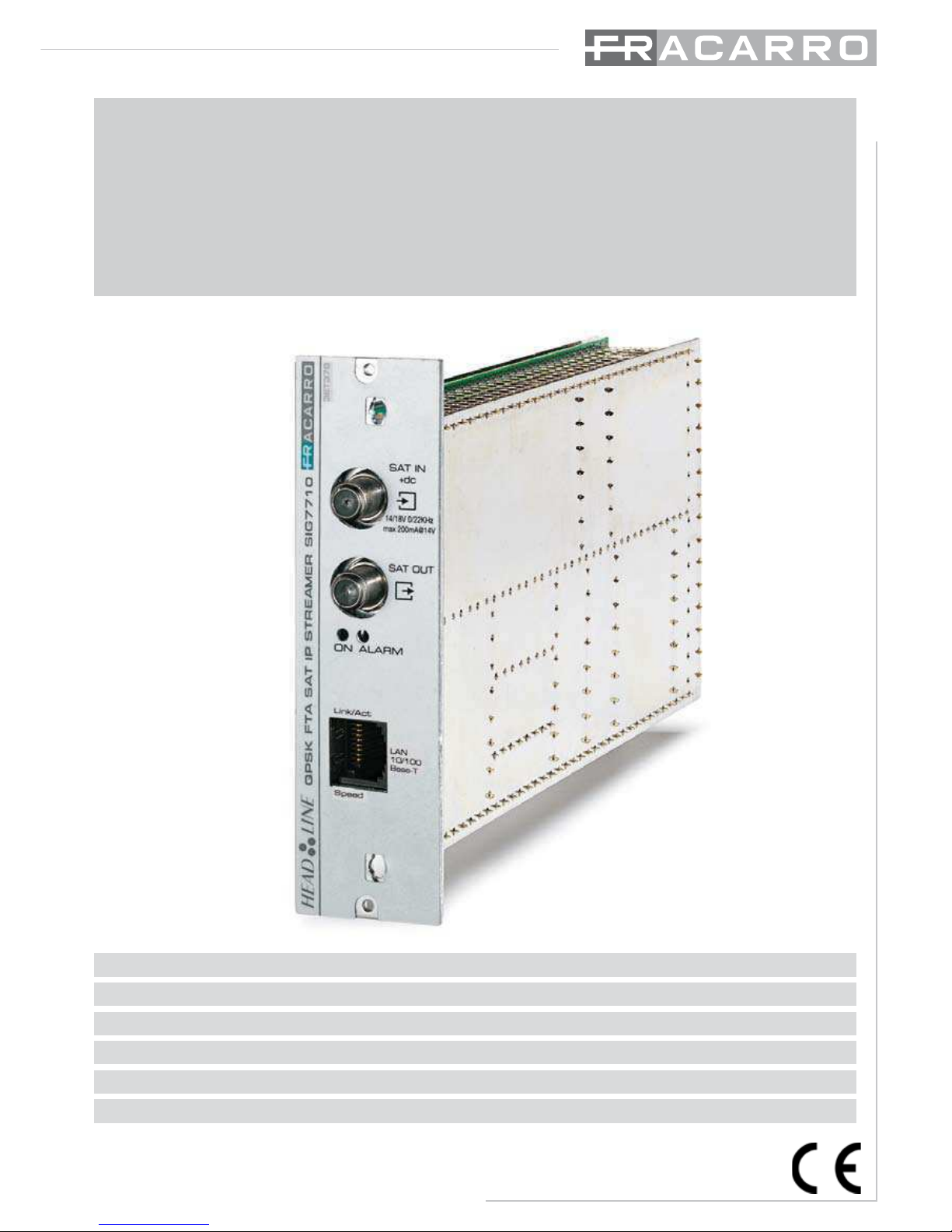
2. PRODUCT DESCRIPTION
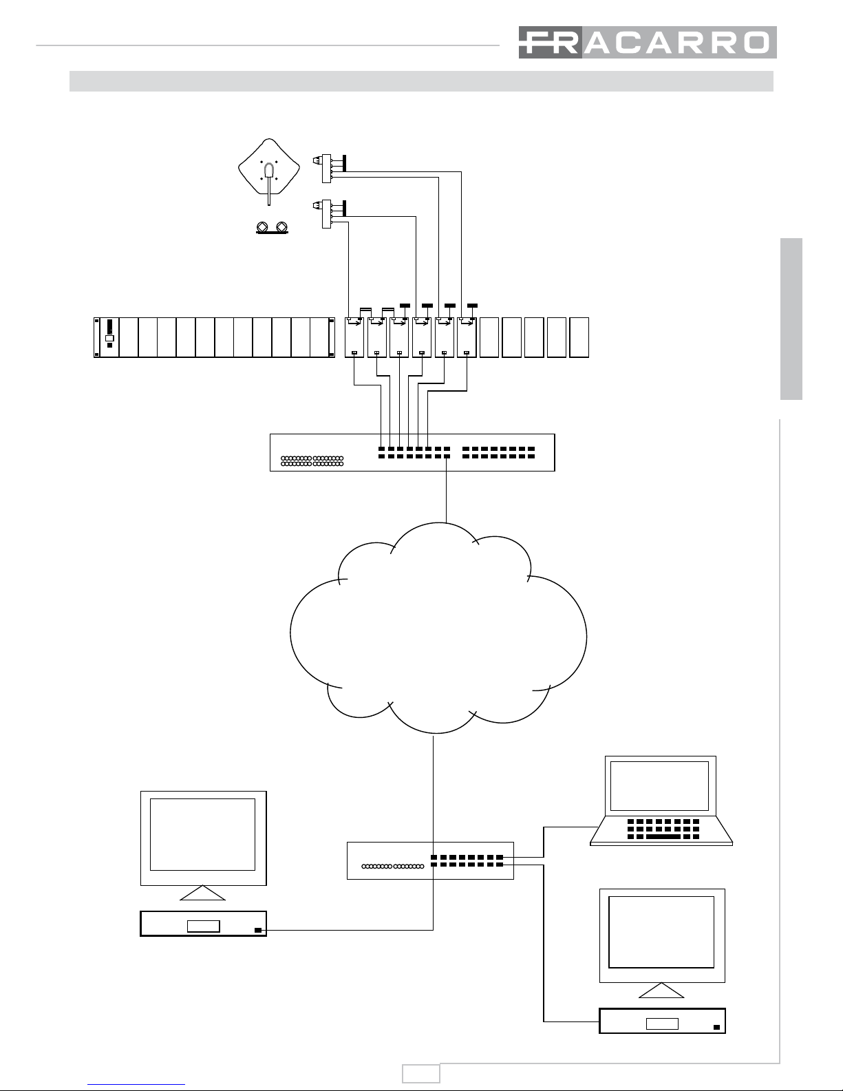
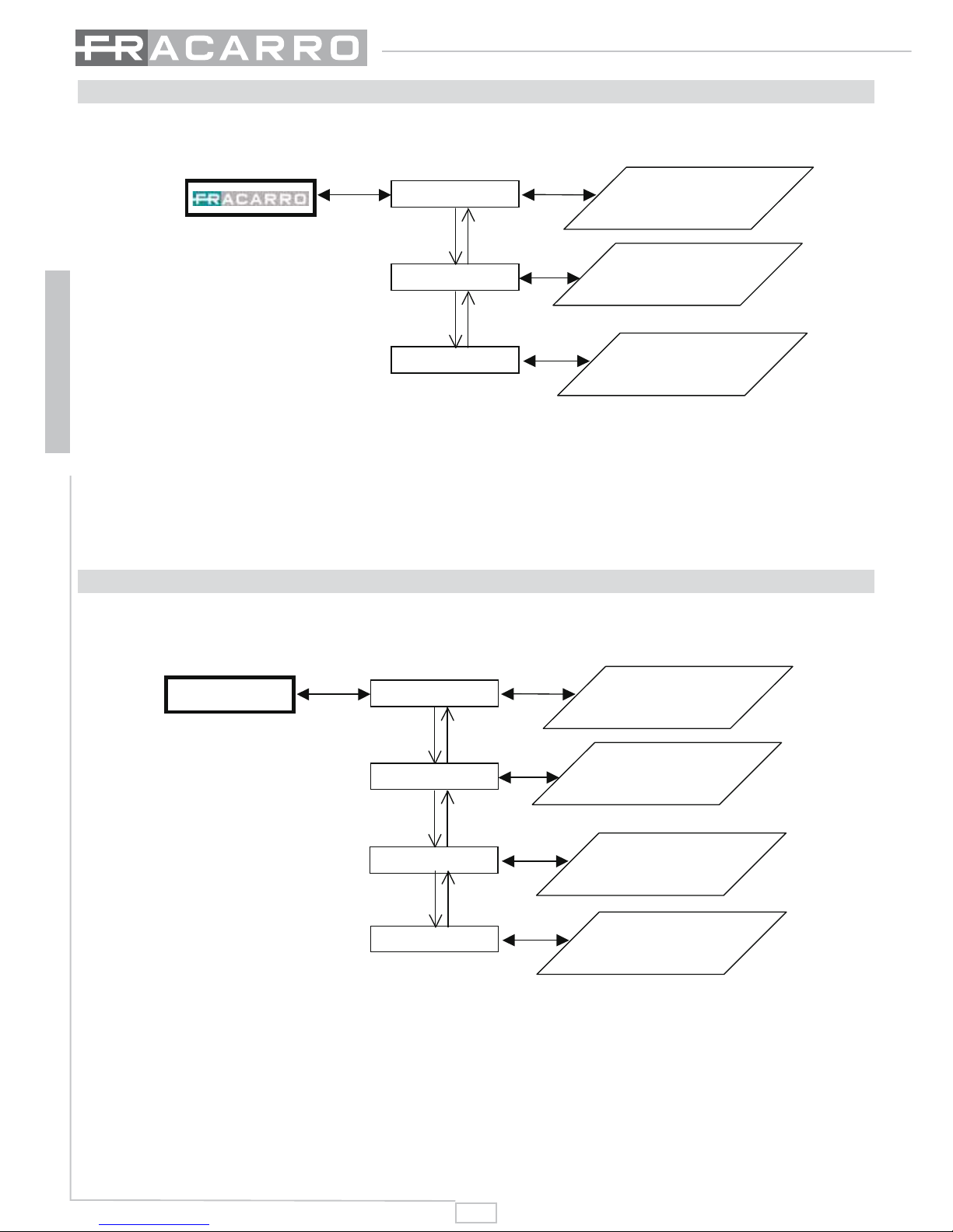
The SIG7710 module receives a digital signal coming from a satellite antenna; it selects a series of pro-
grams within the transponder and sends them to the IP network. The resulting IP stream is sent in mul-
ticast mode to reduce the global IP traffic on the network because it is sent by the Ethernet switches
only to the customers that ask for it.
The signal on the IP is received and displayed by using an IP-Set Top Box or a PC.
Each single SIG7710 module can decode and incapsulate over IP up to 12 video satellite not-crypted
programs maximum; each one of them can be assigned to a single multicast IP address.
IMPORTANT: for the proper functioning of the module is required not to exceed
the 20Mbit/s maximum through output for each SIG7710 module (refer to the
MEASURE -> TOTAL BIT RATE menù on the TPE or WEB MANAGEMENT ->
PROGRAM LIST ->TOTAL BIT RATE on the WEB interface menù).
The device is equipped with the following:
2 input RF connectors (SAT IN – SAT OUT) for SAT IF connection, the SAT signal from the converter
LNB will be connected to the first of the 2 connectors;
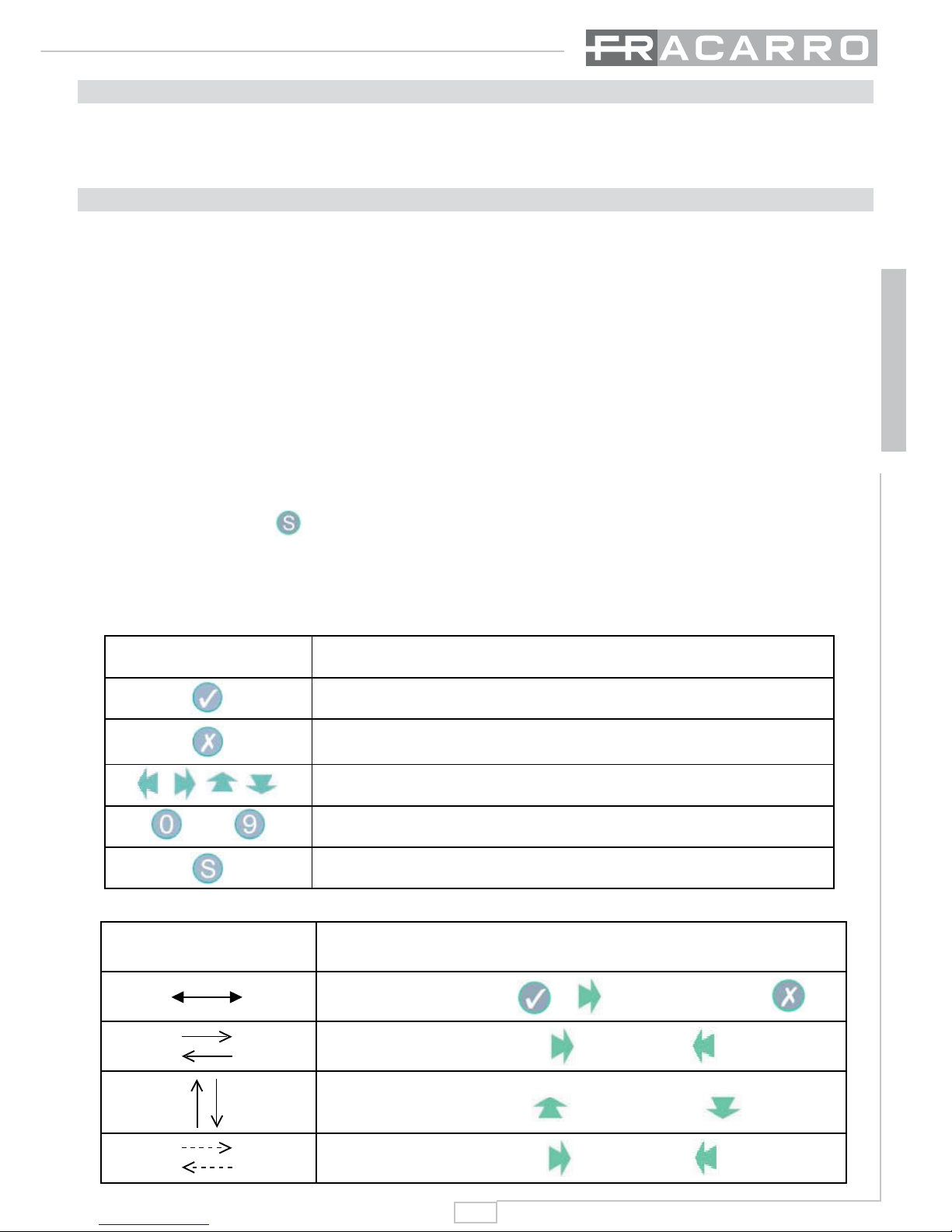
Operation and signalization LED (see summarizing table);
1 RJ-45 connector (LAN 10/100 Base-T) by which it is possible to configure the module parameters
(i.e. Ethernet parameters, INPUT settings, OUTPUT settings) by an integrated web-browser inter-
face. After the configuration it’s possible to connect the module the LAN network.
•
•
•
•
•
•
•
•

25
ENGLISH
NOTE: For easier headend programming PRESET configurations are available.
ATTENTION: see the last pages of these instructions (the TECHNICAL SPECIFICATIONS paragraph) to
know the complete list of technical characteristics.
3. PRODUCT INSTALLATION
The SIG7710 module is installed in the sub-rack of the NewHead Line (SIG7901 or SIG7902) series as
per the following photos. Take the module out of its packaging and install it in the wanted position. The
packing contains the following parts:
SIG7710 module;
Fast jumper for the interconnection (KPR41);
To remove the module use the handles included in the New Headline 19” sub-rack.
•
•
Fig. 1
Fig. 2
After the insertion, fix the modu-
le using the screws contained in
the accessory bag.
It’s a “plug and play” installation;
therefore, the module is ready to
operate.
Insert the module in the card gui-
des and gently push back to lock
them to the back-panel.

26
ENGLISH
4. OPERATION INSTRUCTIONS
Perform the following operations for a proper installation and configuration of the SIG7710 module:
Install the module in the sub-rack (SIG7901 or SIG7902);
Connect the SAT antenna cable to the SAT IN coaxial connector;
Connect the 75 Ohm dummy load to the SAT OUT coaxial connector or use the supplied KPR41
rigid jumper to connect the SAT signal to other New Head Line modules (if available);
Connect the main power supply to the sub-rack;
Wait for the module initialization (the green LED is fixed ON and the red LED is in OFF status);
Connect the TPE to the interconnection module of the sub-rack and carry out the preliminary pro-
gramming operations that are described in the next paragraphs (see the paragraph PROGRAM-
MING INSTRUCTIONS – INITIAL PROGRAMMING THROUGH TPE).
LEDs status summarizing table:
Green LED Red LED Meaning
OFF / Receiver off
Flashing ON Receiver boot
ON Flashing The receiver is supplied properly, but it is not locked
ON OFF The receiver is supplied properly and is locked
ON ON The receiver is supplied properly but there is an
internal fault
Flashing
ON if a fault is present
OFF if it is locked
Flashing if it is not locked
Receiver interrogation
Green LINK Ethernet LED on Ethernet link activated
Green LINK Ethernet LED off Ethernet link not activated
ACTIVITY Ethernet LED flashing Ethernet activity in progress
ACTIVITY Ethernet LED off Ethernet activity lacking
7. Disconnect the TPE and enter the SIG7710 module WEB interface through a PC connection. That
way, the configuration of all operational parameters can be completed (see the paragraph of PRO-
GRAMMING INSTRUCTIONS – SIG7710 WEB MANAGEMENT PROCEDURE);
8. Disconnect the configuration PC and connect the streamer to the local network (see the paragraph
CONNECTION OF THE SIG7710 MODULE TO THE LOCAL NETWORK);
1.
2.
3.
4.
5.
6.

27
ENGLISH
4.1 TYPICAL INSTALLATION EXAMPLE
SAT
HEAD-Line
SIG7710
IP
SAT
HEAD-Line
SIG7710
IP
SAT
HEAD-Line
SIG7710
IP
SAT
HEAD-Line
SIG7710
IP
SAT
HEAD-Line
SIG7710
IP
SAT
HEAD-Line
SIG7710
IP
KPR41
FR
PENTA85
DFP85
CHVU4ZN
LAN
PC
LCD
IP-TV
HEAD
Line
01
SIG7901
HEAD-Line
SIG7904
HEAD-Line
SIG7904
HEAD-Line
SIG7904
HEAD-Line
SIG7904
HEAD-Line
SIG7904
SIG7710
SIG7904
LCD
10:00
IP-TV

28
ENGLISH
5. PROGRAMMING INSTRUCTIONS
The SIG7710 module programming is carried out in 2 consecutive steps:
using the universal TPE programmer, select the IP address of the module and set the main op-
eration parameters, such as the selection of the satellite transponder and the selection of the digital
programs, to be converted (refer to the user’s instructions of the universal programmer and the
SIG7710 GENERAL MENU);
though the local connection between the module and PC. To carry out the local connection to
the module and enter all the configurations through the integrated web-browser interface, use a PC
with a network adapter (Ethernet card) and an Ethernet CAT-5E crossover cable – refer to the PRO-
GRAMMING INSTRUCTIONS – SIG7710 WEB MANAGEMENT PROCEDURE).
1.
2.
SAT
HEAD-Line
SIG7730
IP
SAT
HEAD-Line
SIG7730
IP
SAT
HEAD-Line
SIG7730
IP
SAT
HEAD-Line
SIG7730
IP
SAT
HEAD-Line
SIG7730
IP
SAT
HEAD-Line
SIG7730
IP
KPR41
FR
PENTA85
DFP85
CHVU4ZN
HEAD
Line
01
SIG7901
PC
SIG7730
SAT
HEAD-Line
SIG7730
IP
SAT
HEAD-Line
SIG7730
IP
SAT
HEAD-Line
SIG7730
IP
SAT
HEAD-Line
SIG7730
IP
SAT
HEAD-Line
SIG7730
IP
SAT
HEAD-Line
SIG7730
IP
KPR41
FR
PENTA85
DFP85
CHVU4ZN
HEAD
Line
01
SIG7901
FRACARRO
Freq.In 1204
Lev Out 15
SIG7730

29
ENGLISH
5.1 DEFAULT PARAMETERS
The SIG7710 module can be restored to the original factory settings (default parameters). To set
these parameters, refer to the TPE GENERAL MENU (HEADEND SETUP --> FACTORY SETUP -->
SIG7710).
5.2 INITIAL PROGRAMMING THROUGH THE TPE
Connect the universal TPE programmer to the interconnection module of the sub-rack. The TPE
switches on automatically,
carries out the headend scanning,
the modules contained in the headend are recognized automatically.
Continue with the headend navigation and select the position occupied by the SIG7710 module (refer
to the HEADEND SETUP AND KTP EMULATION MENU).
NOTE: the menu language can be changed. To modify this setting, refer to the GENERAL MENU
OF THE TPE (TPE SETUP --> LANGUAGE). Moreover, it is essential to verify that the set timeout
is equal to 30. To verify this setting, refer to the TPE GENERAL MENU (TPE SETUP --> TIMEOUT
COM).
IMPORTANT: Press the
key of the TPE to save the set parameters. If the key is not pressed
within 5 minutes from the last modification, the set data will be lost and the previous data will be
restored.
1.
2.
3.
Graphic indications of
the menu diagrams Meaning
Select the menu by using or keys and exit with the key
Scroll the menu to the right or to the left
Scroll the menu upwards or downwards
Scroll the value to the right or to the left
TPE keys Key Function
To confirm an entered value or to select a menu
To cancel an entered value or exit a menu
To scroll through menu items
To enter values
To save the modifications
......

30
ENGLISH
5.2.1 TPE GENERAL MENU
5.2.2 SIG7710 GENERAL MENU
HEADEND SETUP
KTP EMULATION
TPE SETUP
TPE settings
Headend or device navigation
Emulation of the KTP
programmer
TPE SETUP MENU
see page 35
HEADEND SETUP MENU
see page 36
KTP EMULATION MENU
see page 36
Confirm the settings by pressing the key; save the settings by
pressing the S key after the modules programmation.
INPUT
MEASURES
NETWORK
Setting the input parameters
Measurements of the input and
output s ignal
NETWORK MENU
see page 31
INPUT MENU
see page 32
MEASURES MENU
see page 35
SIG 7710
OUTPUT
Setting the output
parameters
OUTPUT MENU
see page 34
Confirm the settings by pressing the key; save the settings by
pressing the S key after the modules programmation.

31
ENGLISH
5.2.3 NETWORK MENU
NETWORK
IP ADDRESS
Enabling/disabling
DHCP function
Setting the module IP
address
On Off
DHCP
SUBNET Mask
Setting the module
SUBNET Mask
DEFAULT GATEWAY
Setting the module
DEFAULT GATEWAY
IP ADDRESS
xxx.xxx.xxx.xxx
__.xxx.xxx.xxx
xxx.__.xxx.xxx xxx.__.xxx.xxx
value
xxx.xxx .__.xxx xxx.x xx.__.xx x
value
xxx.xxx .x xx.__ xxx.x xx.x xx.__
value
Exit by
__.xxx.xxx.xxx
value
SUBNET Mask
xxx.xxx .x xx.xxx
Exit by
DEFAULT GATEWAY
xxx.xxx .x xx.xxx
Exit by
Increase/decrease by using
the TPE arrow keys or enter
the v alue directly from the
keyboard.
Increase/decrease by using
the TPE arrow keys or enter
the v alue directly from the
keyboard.
Increase/decrease by using
the TPE arrow keys or enter
the v alue directly from the
keyboard.
__.xxx.xxx.xxx
xxx.__.xxx.xxx xxx.__.xxx.xxx
value
xxx.xxx .__.xxx xxx.x xx.__.xx x
value
xxx.xxx .x xx.__ xxx.x xx.x xx.__
value
__.xxx.xxx.xxx
value
__.xxx.xxx.xxx
xxx.__.xxx.xxx xxx.__.xxx.xxx
value
xxx.xxx .__.xxx xxx.x xx.__.xx x
value
xxx.xxx .x xx.__ xxx.x xx.x xx.__
value
__.xxx.xxx.xxx
value
Confirm the settings by pressing the key; save the settings by
pressing the S key after the modules programmation.
0 65534
WEBSERVER PORT
WARNING: not use
the HTTP port already
occupied by some
others software
process running

32
ENGLISH
5.2.4 INPUT MENU
INPUT PRESET OFF PRESET 1 PRESET 10
SAVE PRESET
Loading …
Select a pre-
memorized c hannel
LNB
Select the LNB
remote power supply OFF 18V/22KHz
OFF
14V/0KHz
18V/0KHz
14V/22KHz
18V/22KHz
DiSEqC
Select the DiSEqC tone A D
satellite A
satellite B
satellite C
satellite D
FREQ.OL (MHz)
Reading the frequency of
the l ocal oscillator AUTO Read-only
FREQ.IF (MHz) 950 2150
Increase/decrease from
TPE by using the arrow
keys, or enter the v alue
directly from the
keyboard.
IF frequency s etting
of the transponder
to be received
SYMBOL RATE 1000 40000
FEC AUTO Read-only
Symbol rate setting of
the transponder
to be received
FEC of the transponder
to be received
CHANNEL LIST 1/N
PROGRAM 1
N/N
PROGRAM N
“Not available”: transponder not
synchronized.
“NONE”: s ervice ID not present
Lis t of the av ailable
channels
Enter by
Enter by
LOAD PRESET
GO TO THE PROGRAM LIST MENU
Confirm the settings by pressing the key; save the settings by
pressing the S key after the modules programmation.

33
ENGLISH
5.2.5 PROGRAM LIST MENU
PROGRAM 1 (*) ENABLE
The program is added in the list
of programs converted i n IP (the
selected program will be
identified by (*)
PROGRAM 2 ( )
PROGRAM “ N” ( )
Refer to the same
programming menus
shown for PROGRAM 1 (*)
Yes No
SERVICE PROP. PROGRAM NAME Program
Program name
name
SERVICE ID Service
Service ID of the
ID of the
selected
selected program
program
Decrease value from the
TPE digit k eyboard
PCR PID PID PCR of the
PID PCR of the selected
selected
program
program
VIDEO PID PID VIDEO of the
PID VIDEO of the
selected
selected program
program
AUDIO PID PID AUDIO of the
PID AUDIO of the
selected
selected program
program
Decrease value from the
TPE digit k eyboard
TELETEXT PID PID TELETEXT of the
PID TELETEXT of the
selected
selected program
program
SERVICE TYPE Type
Type of
of s elected
selected program
program
MULTICAST
GROUP 1 12 Selection of SAT program
multicast IP
Enter by
Confirm the settings by pressing the key; save the settings by
pressing the S key after the modules programmation.

34
ENGLISH
5.2.6 OUTPUT MENU
OUTPUT MULTICAST
GROUP GROUP 1
MULTICAST
IP
MULTICAST
PORT
Refer to the same
programming menus s hown
for GROUP 1 setting
Increase/decrease by
using the TPE arrow
keys or enter the value
directly from the
keyboard.
Increase/decrease
by using the TPE
arrow keys or enter
the v alue directly
from the k eyboard.
GROUP 12
Enter by
RTP LAYER
ENABLE GROUP
MULTICAST PORT
xxxx
1024 65535
ON OFF
ON OFF
MULTICAST IP
xxx.x xx.x xx.xxx
Exit by
(The maximum MULTICAST
GROUP available are 12)
MULTICAST IP reading
MULTICAST PORT reading
__.xxx.xxx.xxx
xxx.__.xxx.xxx xxx.__.xxx.xxx
value
xxx.xxx .__.xxx xxx.x xx.__.xx x
value
xxx.xxx .x xx.__ xxx.x xx.x xx.__
value
__.xxx.xxx.xxx
value
Confirm the settings by pressing the key; save the settings by
pressing the S key after the modules programmation.

35
ENGLISH
5.2.7 MEASUREMENT MENU
5.2.8 TPE SETUP MENU
ME ASURES SOFTWARE VERS.
BER
S/N (dB)
TOTAL BIT RATE
Bit Error Rate
Signal to Noise Ratio
Total Bit Rate
SIG7710 vers. 00
1,3*10E-4
11
20000Kbps
1=not s ynchronized
signal
0=not s ynchronized s ignal
Read-only
Read-only
Read-only
Read-only
TPE SETUP
BAUD RATE 485
Select the language
TIMEOUT COM
CONTRAST LCD
RESET?
Select the
communication rate of
the 485 port
TPE waiting time for
the answer of the
controls s ent to the
headend (timeout
value must be 30)
Regulation of the TPE
display c ontrast
Restore the TPE default
settings
Italian English
English
Italiano
Deutsch
Français
Espanol
Portuguese
9600 115200
1 30
Increase/decrease from TPE
by using the arrow key s, or
enter the v alue directly from
the k eyboard.
0 31
YES=V NO=X
LANGUAGE
9600
19200
38400
57600
115200
BAUD RATE 232 9600 115200
9600
19200
38400
57600
115200
Select the
communication rate of
the 232 port (not active)
Increase/dec rease fromTPE
by using the arrow keys or
enter the value directly from
the k eyboard.
Confirm the settings by pressing the key; save the settings by
pressing the S key after the modules programmation.

36
ENGLISH
5.2.9 HEADEND SETUP AND KIT EMULATION MENU
HEADEND
SETUP
HEADEND SCAN
Navigation in the
headend programming
menus
FACTORY SETUP
SET ADDRESS
RESET MODULE
Automatic
acknowledgement of
the headend connected
to the TPE
Restore the module
defaults setting
Module s earch….
SIG7710 All
modules
NAVIGATION
Automatic search of the
headend or the c onnected
device. After searching, the
main menu can be seen
from the NAVIGATION
function
COPY
Export the headend
configuration to another one
SIG7710
Refer to the SIG7710 general
programming menu
Yes=V NO=X
SIG7710 All
modules
Restart the module
KTP
EMULATION
KTP
EMULATION V=OUTPUT
Emulation of the KTP
programmer
The function i s not
available for the
programming of the
SIG7710 module
NAVIGATION OSD(not available)
Yes=V NO=X
Confirm the settings by pressing the key; save the settings by
pressing the S key after the modules programmation.
Read-only
Address not
Address not v al i d
v al i d

37
ENGLISH
5.3 SIG7710 WEB MANAGEMENT PROCEDURE
After the preliminary programming by the TPE, the advanced programming will be carried out through
the means of the integrated SIG7710 WEB MANAGEMENT interface. (NOTE: WEB interface could
vary depending on the Firmware version loaded in the module).
The procedure is as follows:
1. From the properties of the PC local network card, modify the IP address, setting a new address
belonging to the same sub-network of the SIG7710 module address set. For example:
a. Parameter set in the streamer
i. IP: 192.168.1.1
ii. SUBNET MASK: 255.255.255.0
b. Parameters to be set in the properties of the network card
i. IP: 192.168.1.2
ii. SUBNET MASK: 255.255.255.0
2. Connect the PC to the module by means of a cross RJ-45 cable of CAT-5E;
3. Open the Internet browser (Recommended Browser Internet Explorer);
4. Enter the IP associated to the SIG7710 in the address bar; the following HOME PAGE is displayed.
Select the language for the WEB Interface (English, Français, Deutsch, Italian, Espanol, Portugues).
From this menu, the following options can be selected:
HOME --> Initial page of the integrated WEB configuration device;
INPUT --> Input parameters setting and measurement (frequency of the transponder, SAT polarity se-
lection, value of the Symbol rate, C/N and BER values reading, etc.);
PROGRAM LIST --> Display menu and setting menu for SAT programs sent to the network (program
list, definition of IP multicast groups, etc);
MULTICAST --> Setting of the MULTICAST groups;
NETWORK --> Setting of the module IP parameters;
PRESET --> Factory SAT programs settings;
REBOOT --> SIG7710 module restarting (the operation lasts about 15 seconds; during the restart op-
erations, all the LEDs on the front panel are off).
LOGOUT --> Command to exit the WEB Interface management interface.

38
ENGLISH
5. Enter the NETWORK menu to set/change the IP address, the SUBNET MASK, the WEB SERVER Port
and the DEFAULT GATEWAY previously associated to the streamer (SIG7710). From the module, it is
possible to enable or disable the DHCP function (automatic assignment of the IP address from the net-
work). By default, this option is disabled.
WARNING: not use the HTTP port already occupied by some others software process running.
NOTE – For SIG7710 settings it will be necessary to login once by using Username and Password
(default setting -->
Username --> admin,
Password --> stream_77 ).
After setting all the parameters, confirm them with the SAVE command. Reset an IP address belonging
to the same sub-network in the network card of the local PC that is used for programming.
6 Enter the INPUT menu for the settings relevant to the satellite transponder selections (to modify
the settings for the first time, it is necessary for the user to carry out the authentication by
entering
Username --> admin,
Password --> stream_77 ).
NOTE: from this menu, all the parameters relevant to the selection of the satellite transponder can be set.
In the same picture is present the Status of the Tuner (locked/unlocked) and are displayed BER and
S/N measures.

39
ENGLISH
From this menu, the following options can be selected:
FREQUENCY IF --> 1.a IF frequency setting of the chosen transponder;
LNB --> Selection of the polarity/band satellite parameters;
DiSEqC --> Selection of the orbital position;
Symbol Rate --> Setting the Symbol Rate of the chosen transponder;
After setting all parameters, confirm them with the SAVE control. After about 10 seconds from the PRO-
GRAM LIST menu, it is possible to display all the programs contained in the selected transponder.
7. Enter the MULTICAST menu to define and set all parameters relevant to the MULTICAST groups.
After setting the parameters, confirm them with the SAVE control.

40
ENGLISH
From this menu, the following options can be selected:
Multicast IP --> IP Multicast address settings;
Multicast Port --> setting the port to be used for Multicasting, WARNING: if the RTP option is enabled
port Multicast can only assume equal value between 1024 and 65534. If RTP is disabled if the port
Multicast can take any value between 1024 and 65534.
RTP Layer --> enabling/disabling the Real Time Protocol used in the distribution of the Audio/Video
contents on IP (disable for default);
Enable --> Enabling/disabling the Multicast group;
WARNING: the IP addresses selected for multicasting must be chosen within the 224.0.1.1 -->
239.255.255.255 range. To set addresses and Multicast ports correctly, see the RFC regulations and
the network administrator where the SIG7710 module will be inserted.
8. Re-enter the PROGRAM LIST menu to “send” the video/audio program to the chosen multicast
group according to the following indications:

41
ENGLISH
a. From the “Properties” column, select the “Modify” control to associate the program to the chosen
Multicast group (by default, all programs are associated to the same Multicast group – Group 1);
after setting all parameters, confirm them with the SAVE control.
b. Repeat the operation for each program to be sent to the network, making sure to associate a differ-
ent multicast group for each program;
c. To activate the program in Multicasting transmission, select the “send” control (the program status
will turn from “send” into “stop” and the bit/rate associated to the program will change from 0Kbit/s
to the typical bit/rate value associated to the program – see the following image):
IMPORTANT: for the proper functioning of the module is required not to exceed
the 20Mbit/s maximum through output for each SIG7710 module (refer to the
MEASURE -> TOTAL BIT RATE menù on the TPE or WEB MANAGEMENT ->
PROGRAM LIST ->TOTAL BIT RATE on the WEB interface menù).

42
ENGLISH
d. Repeat the operation for each program that you want to activate on the network.
9. Repeat all the programming operations for all the SIG7710 modules that will make up the headend.
After programming, all streamers can be connected to the main network (refer to the following CON-
NECTION OF THE SIG7710 MODULE TO THE LOCAL NETWORK paragraph).
NOTE: Presets are available for easy and quick SIG7710 settings (see follow menù).
6. CONNECTION OF THE SIG7710 MODULE TO THE LOCAL NETWORK
After programming, the module can be connected to the local LAN network by the CAT-5E patch
cord.
Alla rete LAN
SAT
HEAD-Line
SIG7710
IP
SAT
HEAD-Line
SIG7710
IP
SAT
HEAD-Line
SIG7710
IP
SAT
HEAD-Line
SIG7710
IP
SAT
HEAD-Line
SIG7710
IP
SAT
HEAD-Line
SIG7710
IP
KPR41
FR
PENTA85
DFP85
CHVU4ZN
HEAD
Line
01
SIG7901
HEAD-Line
SIG7904
HEAD-Line
SIG7904
HEAD-Line
SIG7904
HEAD-Line
SIG7904
HEAD-Line
SIG7904
SIG7710
SIG7904
Other manuals for SIG7710
1
Table of contents
Other Fracarro Media Player manuals