Fracarro HOME FIBRE OPT-TX 1510 User manual

HOME FIBRE
OPT-TX 1510 OPT-TX 1530
OPT-TX 1550 OPT-TX 1570
ISTRUZIONI PER L’USO
OPERATING INSTRUCTIONS
INSTRUCTIONS D’EMPLOI

2
Italiano
1. AVVERTENZE PER LA SICUREZZA
L’installazione del prodotto deve essere eseguita da personale qualificato in conformità alle
leggi e normative locali sulla sicurezza. Fracarro Radioindustrie di conseguenza è esonerata da
qualsivoglia responsabilità civile o penale conseguente a violazioni delle norme giuridiche vigenti
in materia e derivanti dall’improprio uso del prodotto da parte dell’installatore, dell’utilizzatore o di
terzi.”
L’installazione del prodotto deve essere eseguita secondo le indicazioni di installazione fornite,
al fine di preservare l’operatore da eventuali incidenti e il prodotto da eventuali danneggiamenti.
Avvertenze per l’installazione
• Utilizzare esclusivamente l’alimentatore fornito in dotazione con il prodotto
• Il prodotto non deve essere esposto a spruzzi d’acqua e va pertanto installato in un ambiente
asciutto, all’interno di edifici.
• Umidità e gocce di condensa potrebbero danneggiare il prodotto. In caso di condensa,
prima di utilizzare il prodotto, attendere che sia completamente asciutto.
• Non installare il prodotto sopra o vicino a fonti di calore o in luoghi polverosi o dove potrebbe
venire a contatto con sostanze corrosive.
• L’eccessiva temperatura di lavoro e/o un eccessivo riscaldamento possono compromettere
il funzionamento e la durata del prodotto.
• Maneggiare con cura. Urti impropri potrebbero danneggiare il prodotto.
• Lasciare spazio attorno al prodotto per garantire una ventilazione sufficiente.
• In caso di montaggio a muro utilizzare tasselli ad espansione adeguati allle caratteristiche del
supporto di fissaggio.
• Non guardare mai dentro ai connettori ottici del < prodotto >. La radiazione laser non è visibile
ad occhio nudo e quindi non è possibile prevenire un danno a lungo termine. Riportare le
immagini delle etichette per le apparecchiature laser.
• Quando si lavora con i connettori ottici del partitore, controllare sempre che i laser di eventuali
trasmettitori ottici ad esso collegati, siano spenti.
Messa a terra dell’impianto d’antenna
Il prodotto deve essere collegato all’elettrodo di terra dell’impianto d’antenna conformemente
alla norma EN 60728-11.
La vite predisposta per tale scopo è contrassegnata con il simbolo
Si raccomanda di attenersi alle disposizioni della norma EN 60728-11 e di non collegare tale vite
(morsetto) (prodotto) alla terra di protezione della rete elettrica di alimentazione.
IMPORTANTE:
Non togliere mai il coperchio del prodotto, parti a tensione pericolosa possono risultare accessibili
all’apertura dell’involucro.
In caso di guasto non tentate di riparare il prodotto altrimenti la garanzia non sarà più valida.
INVISIBLE LASER RADIATION
DO NOT VIEW DIRECTLY WITH
OPTICAL INSTRUMENTS
(MAGNIFIERS)
CLASS 1M LASER PRODUCT
LASER RADIATION
ATTENZIONE:
Radiazione Laser invisibile.
Non osservare direttamente.
Prodotto laser di CLASSE 1M.

3
Italiano
2. DESCRIZIONE DEL PRODOTTO
L’OPT-TX 15X0 è un trasmettitore ottico per la distribuzione di segnali satellitari e digitali terrestri
su un unico cavo in fibra ottica monomodale. I segnali tradizionali RF in ingresso al trasmettitore
OPT-TX 15X0 vengono convertiti e distribuiti su una fibra ottica monomodale che può essere divisa
tramite partitori e derivatori passivi fino a raggiungere molteplici connessioni ottiche (PON=Passive
Optical Network) con un unico trasmettitore. Il segnale ottico potrà poi essere convertito in RF
tramite i ricevitori OPT-RX DT, OPT-RX QUATTRO o OPT-RX TV. Il prodotto prevede l’utilizzo di
un LNB tradizionale e dispone di 5 uscite passanti (4 SAT + 1 TV) per consentire l’installazione in
cascata di altri trasmettitori o l’applicazione in cascata di un sistema tradizionale a multiswitch.
L’AGC (Controllo Automatico del Guadagno) presente sul trasmettitore facilita la configurazione del
prodotto regolando automaticamente il livello del segnale in ingresso al laser ottico.
SAT IN:
connettori F di ingresso per le quattro polarizzazioni satellitari IF (950 ÷ 2150MHz) con
telealimentazione LNB
TV IN: connettore F per l’ingresso del segnale TV (87 ÷ 862MHz)
TEST SAT: connettore F per l’uscita segnale di test SAT, polarità HH, livello per transponder
60dBuV
TEST TV: connettore F per l’uscita segnale TV 87 ÷ 862MHz, potenza complessiva 74dBuV
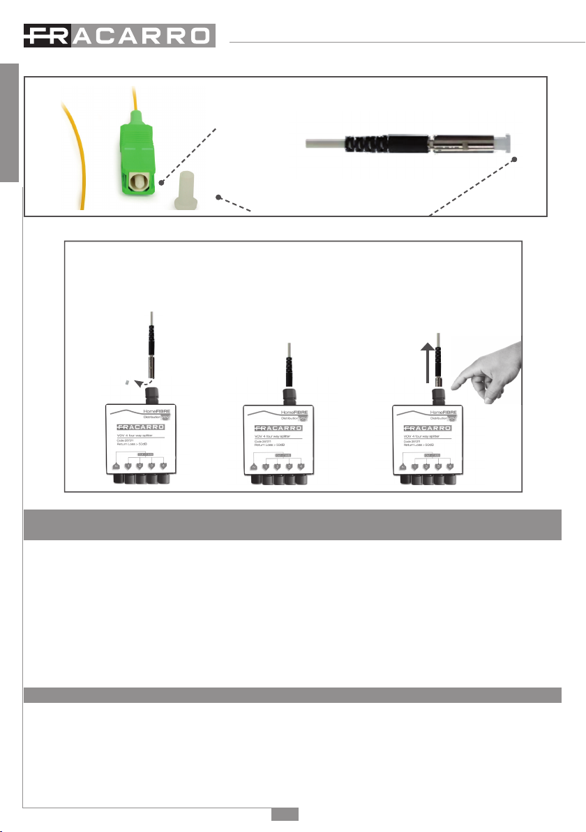
OPTICAL OUTPUT: connettore SC-APC di uscita del trasmettitore ottico per il link in fibra
SAT OUT: connettori F di uscita per le quattro polarizzazioni satellitari IF (950 ÷ 2150MHz) per
eventuale connessione in cascata di altri dispositivi
TV OUT: connettore F per l’uscita del segnale TV (87 ÷ 862MHz)
LED alimentazione: acceso (verde) quando il prodotto è alimentato
LED giallo: l’accensione del LED indica la limitazione di corrente del laser.
Messa a terra dell’impianto d’antenna (secondo EN60728-11)
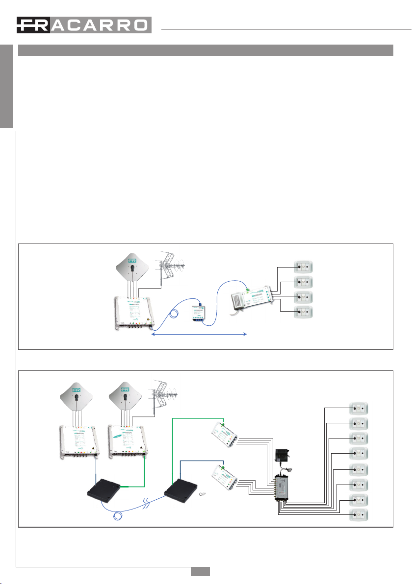
2.1 Funzionamento del sistema:
La distribuzione in fibra ottica ha come impianto di testa un sistema di ricezione di tipo tradizionale e
quindi antenne, parabole e LNB tradizionali ed eventuali centrali di equalizzazione ed amplificazione
dei segnali; i segnali tv e sat vengono inviati ad un trasmettitore ottico OPT-TX 15X0 che trasforma
le variazioni di segnale elettrico in variazioni di segnale luminoso adattando di fatto i segnali per
essere trasferiti a distanza su fibra ottica. La fibra è deputata al trasporto dei segnali.
Ogni qual volta si necessita di dividere questo segnale in più linee al pari degli impianti tradizionali,
si utilizza un dispositivo chiamato divisore ottico o splitter ottico (es. VOV o VOT), il quale suddivide
in più linee di trasporto ottico il segnale senza perdita di qualità, seppur con un’attenuazione
calcolata. Una volta in prossimità dell’unità da servire il segnale ottico viene riconvertito in segnale
tradizionale dai ricevitori ottici (es.OPT-RX DT, OPT-RX QUATTRO, OPT-RX TV) che all’uscita
generano i segnali RF che possono essere messi a disposizione dell’utente finale tramite la
Vista dall’alto OPT-TX 15X0 e indicazioni connettori
}
SAT
Input TV
Input Test
SAT
}
SAT
Output Optical
Output
TV
Output
Test
TV
LED allarme
Connettore di alimentazione
LED alimentazione

4
Italiano
componentistica tradizionale.
2.2 Distribuzione di due o quattro satelliti
Con l’utilizzo dei dispositivi CWDM2 è possibile distribuire due satelliti utilizzando un’unica fibra
ottica. Le uscite ottiche del trasmettitore OPT-TX DT e del trasmettitore OPT-TX 15x0 vanno
miscelate con il dispositivo CWDM2 (287343), utilizzato come miscelatore, ed inserite in
distribuzione utilizzando quindi una sola fibra ottica. La demiscelazione avviene utilizzando lo
stesso dispositivo CWDM2, ma utilizzato come demiscelatore, direttamente prima dei ricevitori:
all’uscita del dispositivo si avranno quindi due fibre, contenenti i segnali dai due trasmettitori, che
andranno inserite nei ricevitori ottici OPT-RX QUATTRO per l’utilizzo di un multiswitch a doppio
satellite. Con l’utilizzo del dispositivo CWDM5MUX e CWDM5DEMUX è possibile distribuire fino
a quattro satelliti ed il servizio internet utilizzando un’unica fibra ottica.
Le uscite ottiche del trasmettitore OPT-TX DT e dei trasmettitori OPT-TX 15x0 vanno miscelate
con il dispositivo CWDM5 MUX (287341) ed inserite in distribuzione utilizzando quindi una sola
fibra ottica. La demiscelazione avviene utilizzando il dispositivo CWDM5 DEMUX (287342)
direttamente prima dei ricevitori: all’uscita del dispositivo si avranno quindi un numero di fibre pari
al numero dei trasmettitori utilizzati che andranno inserite nei ricevitori ottici OPT-RX QUATTRO
per l’utilizzo di un multiswitch a quattro satelliti. I nuovi trasmettitori OPT-TX 15x0 possono essere
quindi installati per l’aggiunta di più satelliti ad un impianto già esistente e sviluppato con l’OPT-TX
DT semplicemente aggiungendo i nuovi OPT-TX 15x0 e i dispositivi CWDM necessari, senza il
passaggio di ulteriori fibre ottiche. Le immagini qui sotto mostrano il funzionamento del ricevitore
OPT-TX 1550 utilizzato da solo e con l’OPT-TX DT per la distribuzione di due satelliti.
attenuazione ottica 21 dB
OPT-RX-DT
VOV 4
OPT-TX 15x0
Distribuzione in fibra ottica con OPT-TX 15x0
1310nm
1550nm
1550nm
1310nm
OPT-RX QUATTRO
OPT-RX QUATTRO
OPT-TX DT OPT-TX 1550
Distribution
CWDM2
OPT-RX QUATTRO
CWDM2
Distribuzione in fibra ottica con OPT-TX DT e OPT-TX 1550
L’ immagine riportata nella pagina seguente mostra un esempio di distribuzione di quattro satelliti

5
Italiano
diversi ed internet utilizzando le frequenze ottiche disponibili.
1510nm
1530nm
1570nm
1550nm
1550nm
1570nm
1530nm
1510nm
OPT-RX QUATTRO
1310nm
Internet
OPT-TX 1510 OPT-TX 1530 OPT-TX 1570 OPT-TX 1550
Distribution
CWDM5 MUX CWDM5 DEMUX
Distribuzione in fibra ottica con OPT-TX 15X0 e internet
3. INSTALLAZIONE DEL PRODOTTO
ATTENZIONE: Non è possibile effettuare un collegamento ottico diretto tra OPT-TX 15x0 e il
ricevitore ottico. Ciò è possibile solo utilizzando attenuatori ottici di linea in modo
da non superare la potenza massima in ingresso al ricevitore. Verificare il livello ottico del segnale
sulla fibra tramite un misuratore ottico prima di collegarla al ricevitore.
3.1 Installazione prodotti
Il trasmettitore OPT-TX 15x0 può essere fissato a muro utilizzando le staffe integrate nella
meccanica del prodotto. Si preveda lo spazio necessario per il collegamento del cavo di
alimentazione e la corretta ventilazione del prodotto (vedi figura).
3.2 Collegamento fibra ottica
Il trasmettitore OPT-TX 15x0 dispone di un connettore ottico SC-APC. In caso di utilizzo di partitori
e derivatori della serie VOV e VOT, utilizzare le bretelle SC-APC -> MINI (PR Adpt, cod. 287226)
per il collegamento alla distribuzione ottica.
Attenzione: Per preservare e proteggere le superfici di contatto dei connettori ottici è buona
regola mantenere le protezioni di bussole e ferule in posizione fino al momento della connessione
o l’eventuale pulizia tramite appositi strumenti dedicati.

6
Italiano
Fibra con connettore SC-APC
Fibra con connettore MINI
Ferula
tappo di protezione della fibra
Installazione e rimozione fibra sui dispositivi VOV e VOT
1) Rimuovere la protezione
dal connettore senza
toccare la ferula
2) Inserire il connettore
seguendo la guida sui
connettori, fino a sentire
un click
3) Per rimuovere la fibra,
premere il connettore ed
estrarre il cavo.
4 ISTRUZIONI PER L’UTILIZZO
4.1 Dimensionamento di un impianto in fibra ottica
Per il dimensionamento dell’impianto in fibra ottica si deve tener conto del livello ottico del segnale
in ingresso ai ricevitori ottici e dunque dell’attenuazione ottica della tratta dato che la potenza
ottica in uscita al trasmettitore OPT-TX 15x0 è compreso tra 5,5 dBm e 6,5 dBm.
Fare riferimento alle caratteristiche tecniche del ricevitore per verificare il valore ottico consentito
al suo ingresso e calcolare quindi l’attenuazione ottica di tratta consentita al sistema.
ATTENZIONE: non sono ammessi collegamenti diretti tra OPT-TX 15X0 e ricevitore,
a meno di utilizzo di opportuni attenuatori ottici di linea.
Se i segnali in ingresso non avessero una qualità ottimale o in caso di distribuzione di un elevato
numero di segnali ad un elevato numero di prese, si consiglia di ridurre il budget ottico o l’utilizzo di
partitori della serie professionale con connettori SC-APC.
4.2 Requisiti del segnale in ingresso al trasmettitore ottico OPT-TX 15x0
Per la corretta trasmissione dei segnali sulla fibra ottica, i segnali RF devono rispettare le seguenti
condizioni:
TV (DTT/CATV)
Per garantire la corretta trasmissione e ricezione dei segnali TV si consiglia di equalizzare i segnali
in ingresso al trasmettitore, soprattutto nel caso di trasmissione di un elevato numero di canali.
Indicativamente i segnali in ingresso devono rispettare le seguenti condizioni:
1. I segnali da trasmettere devono avere un livello ≥74dBuV per poter garantire la corretta ricezione

7
Italiano
da parte dei ricevitori OPT-TX 15X0 anche dopo un’attenuazione ottica di 21dB.
2. Potenza massima d’ingresso (overall input power): -19dBm (90dBuV)
La potenza massima ≤-19dBm (90dBuV) è garantita nei seguenti casi:
•40canaliTVequalizzatia74dBuV
•20canaliTVconlivellomassimo77dBuV
•16canaliTVconlivellomassimo78dBuV
•8canaliTVconlivellomassimo81dBuV
Qualora i segnali TV in ingresso non avessero una qualità ottimale o non fossero correttamente
equalizzati, è consigliabile dimensionare l’impianto tenendo un’attenuazione ottica inferiore a 21dB
per garantire la corretta ricezione del segnale in presa (soprattutto nel caso di trasmissione di un
elevato numero di canali).
FM e DAB
Il livello dei segnali FM e DAB deve essere inferiore di almeno 10dB rispetto alla potenza d’ingresso
(overall input power) del segnale TV
SAT
1. Livello segnali in ingresso: 69÷86dBuV
Il livello dei trasponder in ingresso all’OPT-TX 15x0 deve essere compreso tra 69 e 86dBuV per il
corretto funzionamento dell’ACG (controllo automatico del guadagno)
2. Piattezza in banda: 4dB
E’ consigliato equalizzare i trasponder all’interno della stessa polarità in modo che il dislivello
massimo tra i trasponder da trasmettere su fibra sia di 4dB per garantire la corretta ricezione al
ricevitore.
5. ESEMPI TIPICI DI IMPIANTO
Alcuni schemi di esempio sono disponibili a pagina 26-28 e nel sito www.fracarro.com.
6. SPECIFICHE TECNICHE
Trasmettitore Home Fibre OPT-TX 15x0
Codice Fracarro
Ingressi RF n.° 5 (4SAT + 1TERR)
Uscite RF n.° 7 (4 SAT + 1TERR + 2TEST)
Uscita Ottica n.° 1 SC/APC
INGRESSI SAT
Banda passante MHz 950 ÷ 2150
Tipo di connettore F Femmina
Return loss d’ingresso dB >10
Perdita d’inserzione linea passante dB <2,5
Livello d’ingresso dBµV 69 ÷ 86
INGRESSO TV
Banda passante MHz 87 ÷ 862
Tipo di connettore F Femmina
Return loss d’ingresso dB >10
Perdita d’inserzione linea passante dB <2
Potenza d’ingresso (Potenza complessiva) dBµV 90

8
Italiano
USCITE Test
Banda passante MHz 87 ÷ 862 / 950 ÷ 2150 (polarità HH)
Tipo di connettore F Femmina
Return loss d’ingresso dB >10
Livello uscita Test dBµV 74 (TV) potenza complessiva
60 (SAT) per transponder
USCITA Ottica
Tipo di connettore SC/APC
Lunghezza d’onda nm 1510, 1530, 1550, 1570
Potenza ottica dBm ≥ 5,5
Return loss ottico dB >45
Classe di sicurezza 1M
Caratteristiche principali
Tensione di alimentazione Vac/Hz 184 ÷ 264 / 50 – 60
Potenza consumata W 16
Telealimentazione LNB mA 200@14V (4 connettori SAT)
Temperatura di lavoro °C -5 ÷ +50
Dinamica AGC per modulazione Laser TX dB 20
Segnalazioni luminose Led Verde di alimentazione
Led Giallo limitazione di corrente del laser
Dimensioni l x h x p mm 230x230x50
Miscelatori e demiscelatori ottici CWDM5 MUX CWDM5 DEMUX
Codice 287341 287342
Lunghezza d’onda
nm
1510 – 1530 – 1550 – 1570
nm
C +/- 6,5
Spaziatura canali
nm 20
Perdita di inserzione
dB
<2,3 CWDM OUT <2,3 IN CWDM
Lunghezza d’onda ripple
dB
<0,5
Isolamento canale adiacente
dB
>15 >30
Isolamento canale NON adiacente
dB
>30 >45
Direttività
dB >55
Ingressi e uscite fibra
Tipo di fibra ITU-T-657-A2, G657-B2 And G652-D
Fibra ottica monomodale
Lunghezza fibra mm 1000
Rivestimento fibra um 900
Connettori Tipo SC/APC

9
Italiano
Colori porte COM Nero
1510nm Blu
1530nm Arancio
1550nm Verde
1570nm Marrone
1310nm Bianco
Miscelatori e demiscelatori ottici WDM2
Codice 287343
Lunghezza d’onda
nm 1550-1310
nm
C +/- 20
Perdita di inserzione
dB
<0,5 CWDM OUT <0,5 INCWDM
Wave lenght ripple
dB
<0,5
Isolamento canale
dB
>25
Direttività
dB >55
Fibra
Tipo di fibra ITU-T-657-A2, G657-B2 And G652-D
Fibra ottica monomodale
Lunghezza fibra mm 1000
Rivestimento fibra um 900
Connettori Tipo SC/APC
Colori porte COM Rosso
1310nm Nero
1550nm Giallo
I valori di specifica tipici si riferiscono alla temperatura di esercizio di 25°C.

10
English
1. SAFETY WARNINGS
The product can only be installed by qualified personnel in compliance with local safety laws and
regulations. Fracarro Radioindustrie is free from all civil and criminal responsibility due to breaches
of the current legislation derived from the improper use of the product by the installer, user or
third parties.
The product must be used in full compliance with the instructions given in this manual, in order to
protect the operator against all possible injury and the product from being damaged.
Installation warnings
• Only use the power pack provided with the product
• The product must not be exposed to water drips and must be installed on the inside in dry
atmospheres.
• Damp and condensation drops could damage the product, and consequently always wait
for the product to be perfectly dry before use.
• Do not install the product above or close to sources of heat, in dusty atmospheres or when
it could be exposed to corrosive substances.
• High temperatures or overheating could compromise the product functions and life.
• Handle with care. Knocks could damage the product.
• Leave plenty of space around the product to ensure sufficient ventilation.
• If you wall-mount the product, use expansion anchors that are suitable for the characteristics
of the support bracket.
• Never look into the optical connectors of the < product >. Laser radiation is not visible to the
naked eye and therefore it is not possible to prevent long-term damage. Display the images
of the labels for laser equipment.
• When working with the optical connectors of the divider, always check that the lasers of any
optical transmitters connected to it are turned off.
Earthing the antenna
The product must be connected to the antenna line earth plate, in compliance with the EN60728-
11 standard.
The earth screw is indicated with the symbol
It is important to observe the dispositions of the EN60728-11 standard and not connect this screw
(terminal) (product) to the power supply earth line.
IMPORTANT:
Never remove the product cover: dangerous powered components could be accessible when
the casing is opened.
In case of a malfunction, do not attempt to repair the product because this would invalidate the
guarantee.
INVISIBLE LASER RADIATION
DO NOT VIEW DIRECTLY WITH
OPTICAL INSTRUMENTS
(MAGNIFIERS)
CLASS 1M LASER PRODUCT
LASER RADIATION
WARNING:
Invisible laser radiation.
Do not look directly.
Class 1M laser product.

11
English
2. PRODUCT DESCRIPTION
OPT-TX 15x0 is an optical transmitter for distributing satellite and digital terrestrial signals through a
single-mode fibre optic cable.
The incoming RF signals to the OPT-TX 15x0 transmitter are converted and distributed through a
single-mode fibre optic that can be split by splitters and passive taps enabling them to be sent to
multiple optical connections (PON=Passive Optical Network) using a single transmitter. The optical
signal can be converted into RF using OPT-RX DT, OPT-RX QUATTRO or OPT-RX TV.
The system requires the use of a conventional LNB and provides a traditional 5 core output (4 SAT
+ 1 TV) to enable a cascadable installation to additional transmitters or to a traditional multiswitch
system. The AGC (Automatic Gain Control) in the transmitter makes the product configuration
much easier by automatically adjusting the input signal level to the optical laser.
SAT IN: F input connectors for the four IF satellite polarities (950 ÷ 2150MHz) with LNB remote
power
TV IN: F input connector for the TV signal (87 ÷862MHz)
TEST SAT: F output connector for the SAT test signal, HH polarity, 60dBµV transponder level
TEST TV: F output connector for the TV signal 87 ÷ 862MHz , 74dBµV overall power)
OPTICAL OUTPUT: SC-APC output connector for the optical transmitter for the fibre link
SAT OUT: F output connectors for the four IF satellite polarities (950 ÷ 2150MHz) for possible
cascade applications to other devices
TV OUT: F output connector for the TV signal (87 ÷ 862MHz)
POWER ON LED: On (green) to show the product is turned on.
ALARM LED: when ON, it shows the limitation of the laser power.
Earthing the antenna installation (according to EN60728-11 standard).
2.1 System Functions
The headend system in a fibre optic distribution network uses traditional receptive devices, i.e.
aerials, dishes and traditional LNB’s and any signal equalisation and amplification units.
TV and SAT signals are sent to an OPT-TX 15x0 optical transmitter, which converts the electrical
signals into luminous signals, therefore enabling the distribution via a fibre optic infrastructure over
long distances. The fiber optic carries the signals.
Like traditional systems, each time this signal has to be split over a number of lines, a device called
an optical divider or optical splitter (VOV or VOT) is used to split the signal into a number of optical
transport lines without any fall in quality even with a calculated attenuation.
Once the optical signal is in the vicinity of the unit to be served, it is reconverted into a traditional
signal by the OPT-RX DT or OPT-RX QUATTRO or OPT-RX TV optical receivers which on output
generate the RF signals provided to the end user by means of traditional components.
PLANT VIEW OF OPT-TX 15x0 TRANSMITTERS AND CONNECTOR INDICATIONS
}
SAT
Input TV
Input Test
SAT
}
SAT
Output Optical
Output
TV
Output
Test
TV
LED allarme
Connettore di alimentazione
LED alimentazione

12
English
2.2 Two or four satellite distribution
By means of the CWDM2 device, two satellites can be distributed, utilizing only one fibre optic.
The optic outputs of the OPT-TX DT and OPT-TX 15x0 transmitters are mixed with the CWDM2
(287343) device, which is used as a mixer, and inserted into the distribution by using only one fibre
optic. Demixing is performed by the same CWDM2 device which is then used as a demixer and
is positioned before the receivers. At the device output, there are two fiber optics containing the
signals from the two transmitters. The two fibre optics will be inserted into the OPT-RX QUATTRO
optical receivers for the use of a double satellite multiswitch. By means of the CWDM5MUX and
CWDM5DEMUX device, up to four satellites and Internet service can be distributed with
only one fibre optic.
The optic outputs of OPT-TX DT and OPT-TX 15x0 transmitters are mixed with the CWDM5
MUX (287341) device and inserted into the distribution by using only one fiber optic. Demixing
is performed by the CWDM5 DEMUX device (287342) which is positioned before the receivers.
At the device output, there are as many fiber optics as the number of the used transmitters; the
fibre optics will be inserted into the OPT-RX QUATTRO optical receivers to use a four satellite
multiswitch.
Therefore, the new OPT-TX 15x0 transmitters can be installed to add satellites to an old installation
developed with OPT-TX DT by adding the new OPT-TX 15x0 receiver and the CWDMs, without
adding other fiber optics.
The following figures show the operation of the OPT-TX 1550 receiver used alone as well as with
the OPT-TX DT unit for the distribution of two satellites.
attenuazione ottica 21 dB
OPT-RX-DT
VOV 4
OPT-TX DT
Fibre optic distribution through OPT-TX DT
1310nm
1550nm
1550nm
1310nm
OPT-RX-DT QUATTRO
OPT-RX-DT QUATTRO
OPT-TX DT OPT-TX DT
3W
Distribution
WDM
OPT-RX-DT QUATTRO
WDM
Fibre optic distribution through OPT-TX DT and OPT-TX 1550

13
English
The figure below gives the example of a distribution of four different satellites and Internet.
1510nm
1530nm
1570nm
1550nm
1550nm
1570nm
1530nm
1510nm
OPT-RX-DT QUATTRO
1310nm
Internet
OPT-TX DT
3W OPT-TX DT
3W OPT-TX DT
3W OPT-TX DT
3W
Distribution
WDM
WDM
Fibre optic distribution through OPT-TX 15X0 and internet
3.1 Product installation
ATTENTION: A direct optical connection cannot be made between the OPT-TX 15x0 and the
optical receiver. The connection can only be made using optical line attenuators in order to not
exceed the overall input power on the optical receiver.
Check the optical level of the signal on the fibre using an optical light meter before connecting it
to the optical receiver. The transmitter OPT-TX 15x0 can be wall mounted using the brackets that
are incorporated in the product mechanics. The space is provided for connecting the power lead
and for correct ventilation of the product (see figure below).
3.2 Fibre optic connection
Fibre with connector SC-APC
Fibre with MINI connector
Ferule
protective cap
The OPT-TX 15X0 transmitter has an SC-APC optical connector.
If splitters and taps VOV and VOT series are used, use the SC-APC -> MINI links (PR ADAPT, code
287226) for the connection to the optical distribution.

14
English
Attention: To conserve and protect the contact surfaces of the optical connectors, the bushing
and ferule protectors should be left in position until the connections are made or can be cleaned
using the proper tools.
Installing and removing the fibre cable to the VOV and VOT devices:
1) Remove the protective
cover from the connector
without touching the ferule.
2) Insert the connector
following the guides until it
clicks into place.
3) To remove the fibre,
press the connector and
pull out the cable.
4 USER INSTRUCTION
4.1 Dimensioning a Fibre Optic System
When designing a fibre optic system it is important to consider the optical input level to the
optical receivers, suitable attenuation is required and must be calculated as the optical output
power of OPT-TX 15X0 transmitter ranges between 5.5dBm and 6.5dBm. Refer to the technical
characteristics of the receiver to check the value allowed on its optical input and then calculate the
optical attenuation allowed on the system.
ATTENTION: direct connections are not allowed between the OPT-TX 15x0 unit
and the receiver, unless the correct line optical attenuators are used.
If the quality of the input signals is not optimised, or if a lot of signals have to be distributed to a
lot of sockets, the optical budget should be reduced or professional splitters should be used with
SC-APC connectors.
4.2 Requirements of the input signal to the OPT-TX 15x0
For the signals to be correctly transmitted through the fibre optic, the RF signals must respect the
following requirements:
TV (DTT/CATV)
To ensure the TV signals are transmitted and received correctly, the input signals to the transmitter
should be equalised, especially if a lot of channels are being transmitted.
As an indication, the input signals should respect the following requirements:
1. The transmitter signal level should be ≥74 dBµV to guarantee correct reception by the receivers,
even after an optical attenuation of 21dB.
2. Overall input power: ≤-19 dBm (90 dBµV).
The overall power ≤-19 dBm (90 dBµV) is guaranteed in the following cases:
•40TVchannelsequalisedat74dBµV
•20TVchannelswithamaximumlevelof77dBµV
•16TVchannelswithamaximumlevelof78dBµV
•8TVchannelswithamaximumlevelof81dBµV
If the TV input signal quality is not optimal or not correctly equalised, then the system should be
designed considering an optical attenuation lower than 21dB to guarantee correct signal reception

15
English
at the socket (especially when a lot of channels are being transmitted).
FM e DAB
The FM and DAB signal levels should be at least 10dB lower than the overall input power of the
TV signal.
SAT
1. Input signal level: 69 86 dBµV
The input transponder level to the OPT-TX 15x0 must be between 69 and 86 dBµV for the ACG
(automatic gain control) to function correctly.
2. Band flatness: 4dB
The transponders should be equalised within the same polarity so that the maximum difference
in level between the transponders transmitting through the fibre is 4dB, to ensure the receiver is
able to receive correctly.
5. TYPICAL INSTALLATION EXAMPLES
Some example diagrams are available at the end of the manual and on the website www.fracarro.
com.
6. TECHNICAL SPECIFICATIONS
Home Fibre Transmitter OPT-TX 15X0
Fracarro Code
RF inputs n.° 5 (4 SAT + 1 TERR)
RF outputs n.° 7 (4 SAT + 1TERR + 2TEST)
Optical output n.° 1 SC/APC
SATELLITE INPUTS
Bandwidth MHz 950 ÷ 2150
Connectors type F Female
Input return losses dB >10
Trunk line insertion loss dB <2,5
RF input level dBµV 69 ÷ 86
TERRESTRIAL INPUT
Bandwidth MHz 87 ÷ 862
Connectors type F Female
Input return loss dB >10
Trunk line insertion losses dB <2
RF input level dBµV 90
TERRESTRIAL INPUT
Bandwidth MHz 87 ÷ 862 / 950 ÷ 2150 (HH polarity)
Connector type F Female
Input return loss dB >10
Output level Test dBµV 74 (TV) overall power
60 (SAT) per transponder

16
English
OPTICAL OUTPUT
Connector type SC/APC
Wavelength nm 1510, 1530, 1550, 1570
Optical output power dBm ≥ 5,5
Optical return loss dB >45
Safety class 1M
Main Features
Mains voltage Vac/Hz 184 ÷ 264 / 50 – 60
Power consumption W 16
LNB remote powering mA 200@14V (4 connectors SAT)
Operating temperature °C -5 ÷ +50
AGC RF level dynamics dB 20
LED information Power on: green LED
Extracurrent on laser: yellow LED
Dimensions L x H x W mm 230x230x50
Optical multiplexer - demultiplexer CWDM5 MUX CWDM5 DEMUX
Fracarro Code 287341 287342
CWDM center wavelenght
nm
1510 – 1530 – 1550 – 1570
nm
C +/- 6,5
Channel Spacing
nm 20
CWDM Insertion loss
dB
<2,3 CWDM OUT <2,3 IN CWDM
Wave lenght ripple
dB
<0,5
Adjacent channel isolation
dB
>15 >30
NON-adjacent channel isolation
dB
>30 >45
Directivity
dB >55
Fibre input and output
Fibre type ITU-T-657-A2, G657-B2 And G652-D Compliant
Single Mode Fiber
Fibre lenght nm 1000
Fibre Jacket um 900 tight buffer
Connectors Type SC/APC
Port Identification Color COM Black
1510nm Blue
1530nm Orange
1550nm Green
1570nm Brown
1310nm White

17
English
Unless otherwise specified, the values given refer to the operating temperature of 25° C.
Optical multiplexer - demultiplexer WDM2
Fracarro Code 287343
CWDM center wavelenght
nm 1550-1310
nm
C +/- 20
CWDM Insertion loss
dB
<0,5 CWDM OUT <0,5 INCWDM
Wave lenght ripple
dB
<0,5
Channel isolation
dB
>25
Directivity
dB >55
Fibre input and output
Fibre type ITU-T-657-A2, G657-B2 And G652-D Compliant
Single Mode Fiber
Fibre lenght nm 1000
Fibre Jacket um 900 tight buffer
Connectors Type SC/APC
Port Identification Color COM Red
1310nm Black
1550nm Giallo

18
Français
1. AVERTISSEMENTS DE SÉCURITÉ
Le produit doit être installé par du personnel qualifié, conformément aux lois et réglementations
locales en matière de sécurité. Fracarro Radioindustrie est par conséquent déchargée de toute
responsabilité civile ou pénale conséquente à des violations des normes juridiques en vigueur en
la matière et dérivant de l’usage incorrect du produit de la part de l’installateur, de l’utilisateur ou
de tiers.
Le produit doit être installé en suivant les indications fournies, afin de préserver l’opérateur
d’éventuels accidents et le produit d’éventuels endommagements.
Avertissements d’installation
• N’utiliser que l’alimentation fournie avec le produit
• Le produit ne doit pas être exposé à l’égouttement ou à des jets d’eau ; il doit donc être
installé dans un environnement sec, à l’intérieur de bâtiments.
• L’humidité et les gouttes de condensation pourraient endommager le produit.
En cas de condensation, attendre que le produit soit complètement sec avant de l’utiliser.
• Ne pas installer le produit sur ou à proximité de sources de chaleur ou dans des endroits
poussiéreux ou bien dans des endroits où ils pourraient entrer en contact avec des
substances corrosives.
• La température excessive de fonctionnement et/ou un réchauffement excessif peuvent
nuire au fonctionnement et à la durée du produit.
• Manier avec soin. Les chocs pourraient endommager le produit.
• Laisser assez de place autour du produit, afin de garantir une aération suffisante.
• En cas de montage mural, utiliser des chevilles à expansion correspondant aux
caractéristiques du support de fixation.
• Ne jamais regarder à l’intérieur des connecteurs optiques du < produit >. La radiation laser
n’est pas visible à l’œil nu et il n’est donc pas possible de prévenir un dommage à long terme.
Reporter les images des étiquettes pour les appareils laser.
• Lors du travail avec les connecteurs optiques du diviseur, toujours contrôler que les lasers
d’éventuels transmetteurs optiques liés à celui-ci sont éteints.
Mise à la terre de l’antenne
Le produit doit être relié à l’électrode de terre de l’antenne conformément à la norme EN60728-11.
La vis prévue à cet effet est caractérisée par le symbole.
Il est conseillé de respecter les dispositions de la norme EN60728-11 et de ne pas relier cette vis
(borne) (produit) à la terre de protection du secteur.
IMPORTANT:
• Ne jamais ôter le couvercle du produit ; des pièces sous tension dangereuses peuvent être
accessibles si le couvercle est ouvert.
En cas de panne, ne pas tenter de réparer le produit, sans quoi la garantie ne sera plus valable
INVISIBLE LASER RADIATION
DO NOT VIEW DIRECTLY WITH
OPTICAL INSTRUMENTS
(MAGNIFIERS)
CLASS 1M LASER PRODUCT
LASER RADIATION
ATTENTION:
Rayonnement laser invisible.
Ne regardez pas directe-
ment.
Produit laser de classe 1M.

19
Français
2. DESCRIPTION DU PRODUIT
OPT-TX 15x0 est un transmetteur optique pour la distribution des signaux satellites et terrestres sur
un seul câble à fibre optique monomodale.
Les signaux traditionnels RF en entrée au transmetteur OPT-TX 15X0 sont convertis et distribués
sur une fibre optique monomodale qui peut être divisée au moyen de diviseurs passifs jusqu’à
atteindre plusieurs connexions optiques (PON=Passive Optical Network) au moyen d’un seul
transmetteur. Le signal optique pourra être ensuite converti en RF au moyen des receveurs OPT-
RX DT, OPT-RX QUATTRO ou OPT-RX TV.
Le produit prévoit l’utilisation d’un LNB traditionnel et dispose de 5 sorties passantes (4 SAT + 1 TV)
pour permettre l’installation en cascade d’autres transmetteurs ou l’application en cascade d’un
système traditionnel à interrupteurs multiples. L’AGC (Contrôle Automatique du Gain) présent sur
le transmetteur facilite la configuration du produit en réglant automatiquement le niveau du signal
en entrée au laser optique.
SAT IN: connecteurs F d’entrée pour les quatre polarisations satellites IF (950 ÷ 2150MHz) avec
téléalimentation LNB
TV IN: connecteur F pour l’entrée du signal TV (87 ÷ 862MHz)
TEST SAT: connecteur F pour la sortie du signal de test SAT, polarité HH, niveau pour
transpondeur 60dBuV
TEST TV: connecteur F pour la sortie du signal TV 87 ÷ 862MHz, puissance totale 74dBuV
OPTICAL OUTPUT: connecteur SC-APC de sortie du récepteur optique pour le lien à fibre
SAT OUT: connecteurs F de sortie pour les quatre polarisations satellites IF (950 ÷ 2150MHz)
pour le branchement éventuel en cascade d’autres dispositifs
TV OUT: connecteur F pour la sortie du signal TV (87 ÷ 862MHz)
LED alimentation: allumée (verte) lorsque le produit est alimenté
LED alarme: l’accensione del LED indica la limitazione di corrente del laser.
Mise à terre du système (en suivant EN60728-11).
2.1 Fonctionnement du système
L’unité de tête dans la distribution en fibre optique est un système de réception de type traditionnel
comprenant donc des antennes, des paraboles et des LNB traditionnels et d’éventuelles unités
centrales d’égalisation et d’amplification des signaux ; les signaux tv et sat sont envoyés à un
transmetteur optique OPT-TX 15x0 qui transforme les variations du signal électrique en variations
du signal lumineux en utilisant les signaux qui sont transférés à distance sur fibre optique. La fibre
est réservée au transport des signaux.
Chaque fois qu’il est nécessaire de diviser le signal en plusieurs lignes comme dans les installations
traditionnelles, un dispositif appelé diviseur optique ou splitter optique (ex. VOV ou VOT) est utilisé.
Vue du haut du transmetteur OPT-TX 15x0 et indication des connecteurs
}
SAT
Input TV
Input Test
SAT
}
SAT
Output Optical
Output
TV
Output
Test
TV
LED allarme
Connettore di alimentazione
LED alimentazione

20
Français
Ce dispositif divise le signal en plusieurs lignes de transport optique sans perte de qualité, mais
avec une atténuation calculée.
Lorsque le signal optique est à proximité de l’unité à servir, il est converti en signal traditionnel par
les receveurs optiques (ex. OPT-RX DT, OPT-RX QUATTRO, OPT-RX TV) qui engendrent à la sortie
les signaux RF qui arrivent à l’utilisateur final au moyen des composants traditionnels.
2.2 distribution de deux ou quatre satellites
Le dispositif CWDM2 permet de distribuer deux satellites en utilisant une seule fibre optique.
Les sorties optiques du transmetteur OPT-TX DT et du transmetteur OPT-TX 15x0 sont mélangées
avec le dispositif CWDM2 (287343), utilisées comme mélangeur, et insérées en distribution
en utilisant une seule fibre optique. Le dé-mélange est effectué en utilisant le même dispositif
CWDM2 utilisé comme un dé-mélangeur, directement en amont des récepteurs : à la sortie du
dispositif il y a donc deux fibres contenant les signaux provenant des deux transmetteurs, qui
seront insérées dans les récepteurs optiques OPT-RX QUATTRO pour l’utilisation d’interrupteurs
multiples à deux satellites.
Au moyen du dispositif CWDM5MUX et CWDM5DEMUX il est possible de distribuer jusqu’à
quatre satellites et le service internet. Les sorties optiques du transmetteur OPT-TX DT
et des transmetteurs OPT-TX 15x0 sont mélangées avec le dispositif CWDM5 MUX (287341) et
insérées en distribution en utilisant donc une seule fibre optique. Le dé-mélange est effectué en
utilisant le dispositif CWDM5 DEMUX (287342) directement en amont des receveurs : à la sortie
du dispositif il y aura donc un nombre de fibres égal au nombre de transmetteurs utilisés qui
seront insérés dans les receveurs optiques OPT-RX QUATTRO pour l’utilisation d’un interrupteur
multiple à quatre satellites.
Les nouveaux transmetteurs OPT-TX 15x0 peuvent donc être installés pour ajouter plusieurs
satellites dans une installation déjà existante et développée au moyen de l’OPT-TX DT tout
simplement en ajoutant les nouveaux OPT-TX 15x0 et les dispositifs CWDM nécessaires, sans
devoir faire passer d’ultérieures fibres optiques.
Les images ci-dessous illustrent le fonctionnement du receveur OPT-TX 1550 utilisé seul ou avec
l’OPT-TX DT pour la distribution de deux satellites.
attenuazione ottica 21 dB
OPT-RX-DT
VOV 4
OPT-TX DT
Distribution en fibre optique OPT-TX DT
This manual suits for next models
7
Table of contents
Languages:
Other Fracarro Transmitter manuals