Fractal FC-6 User manual

Manual Version 1.03 — January 2019

Inside Front Cover

i
Declaration of Conformity
Manufacturer’s Name: Fractal Audio Systems, LLC
Manufacturer’s Address: 4 Wilder Drive, Plaistow, NH 03865 USA
Declares that the product:
Product name: FC Controller
Product option: FC-6, FC-12
Safety: EN60065:2014
EMC: EN55013:2013
EN55020:2007+A11:2011
EN55024:2010
EN61000-3-2:2014
EN61000-3-3:2013
Supplementary Information:
The product herewith complies with the requirements of
the Low Voltage Directive 2006/95/EC
and the EMC Directive 2004/108/EC.
Clifford Chase, President / CEO
December 21, 2018
EMC/EMI
This equipment has been tested and found to comply with the limits for a Class B Digital device,
pursuant to part 15 of the FCC rules. These limits are designed to provide reasonable protection
against harmful interference in residential installations. This equipment generates, uses and can
radiate radio frequency energy and, if not installed and used in accordance with the instructions,
may cause harmful interference to radio communications. There is no guarantee that interference
will not occur in a particular installation. If this equipment does cause harmful interference to
radio or television reception, which can be determined by turning the equipment off and on, the
user is encouraged to try to correct the interference by one or more of the following measures:
Reorient or relocate the receiving antenna.
Increase the separation between the equipment and receiver.
Connect the equipment to an outlet on a circuit different from that to which the receiver is connected.
Consult the dealer or an experienced radio/TV technician for help.

ii
Legal Notices
Fractal Audio Systems FC-6 & FC-12 Owner’s Manual. Contents Copyright © 2018. All Rights Reserved.
With the exception of one hard copy for personal use, no part of this publication may be reproduced in any form without the express
written permission of Fractal Audio Systems.
Fractal Audio, the Fractal Audio Systems logo, Axe-Fx, Humbuster, UltraRes, FASLINK are trademarks of Fractal Audio Systems.
Manufacturer names and product names mentioned herein are trademarks or registered trademarks of their respective owners,
which are in no way associated with or afliated with Fractal Audio Systems, LLC. The names are used only to illustrate sonic and
performance characteristics.
WARNING: To reduce the risk of re or electric shock, do not expose this
appliance to rain or moisture.
CAUTION: To reduce the risk of re or electric shock, do not remove screws.
There are no user serviceable parts inside. Refer servicing to qualied service
personnel.
Important Safety Instructions
1. Obey any warnings on the FC chassis and in this User Guide.
2. Keep away from sources of heat such as ducts, registers or appliances that produce heat.
3. Connect only to FASLINK II connector or to an AC Adapter rated at 9V DC 1000ma.
4. Keep all cables in good condition. Do not kink, bend, or pinch.
5. If not using your FC for extended periods of time, disconnect from power.
6. Protect the unit from rain and excessive moisture.
7. Refer servicing to qualied personnel only.
8. Stop operation of the unit and obtain service if:
- Liquids or excessive moisture enter the unit.
- The unit operates incorrectly or performance is inconsistent or erratic.
- The unit has been dropped and/or the enclosure damaged.
9. Prolonged exposure to high volume levels can cause hearing damage and/or loss. The use of
hearing protection in high volume situations is recommended.
A Manual for Online and Print Use
This manual is intended for use in desktop, tablet, and smart phone readers. It includes clickable links and
bookmarks to make navigation and cross-reference easy. We recommend against printing, because rmware
updates tend to make older manual versions fall out of date. That said, considerations have been taken for those
who prefer paper. You are granted permission to print this PDF for personal use only. A copy center or online printer
can print and bind a book for you from the PDF le. Those using screen readers must forgive the changes made
herein to accommodate the print version: all links also include a page or section numbers, page spreads have extra
margins towards the binding edge, and blank pages have been included to preserve page and chapter flow.

iii
TABLE OF CONTENTS
1 INTRODUCTION ............. 1
Welcome to the FC ................... 1
Feature Summary ....................2
2 HARDWARE OVERVIEW ....... 3
The Top Panel .......................3
The Rear Panel ......................4
3 SETTING UP................ 5
Basics .............................5
Daisy Chaining ......................8
Mirroring ...........................9
MIDI Connections ...................10
4 LAYOUTS & SWITCHES....... 11
The Master Layout Menu. . . . . . . . . . . . . . 11
Tap & Hold Functions ................12
Example Layouts....................13
Factory Default Layouts ..............14
Easy (“EZ”) Edits ....................17
The Layouts List ....................19
Edit A Layout .......................20
Edit A Switch.......................21
Naming Layouts ....................22
Startup Layouts.....................22
5 FOOTSWITCH FUNCTIONS .... 23
LED Ring Colors. . . . . . . . . . . . . . . . . . . . . 23
The “UNASSIGNED” Function ..........23
Bank Functions .....................24
Preset Functions ....................26
Scene Functions ....................28
Effect Functions ....................29
Utility Functions ....................31
Layout Functions....................32
Looper Functions ...................33
Per-Preset Functions.................34
Control Switch Functions .............36
The Layout Link Feature .............. 38
6 TRANSMITTING MIDI ........ 39
The Scene MIDI Block ................39
Control Switch MIDI .................39
7 THE CONFIG MENU ......... 41
8 ADDITIONAL TOPICS ........ 43
Firmware ..........................43
Backups ..........................43
Axe-Edit...........................43
FC-6: Short Tutorial ..................44
FC-12: Short Tutorial ................46
Specications ......................48
Warranty .......................... 49
EULA .............................50

iv
This page preserves page facing in the printed manual.

1
1 INTRODUCTION
The new FC-6 and FC-12 Foot Controllers for the Axe-Fx III are the perfect way to control your performances with
the world’s most powerful guitar processor. Our latest-generation controllers offer an impressive suite of features
and capabilities, incorporating years of innovation and customer feedback. They look great too, making an
attractive addition to your home, studio or stage.
The FC-12 and FC-6 are easy to use while still granting extreme flexibility. For those who want simplicity, the
units are virtually plug-and-play. Use the “Master Layout Menu” to select from “Layouts.” Layouts are like pages
of footswitches arranged in familiar and intuitive ways, and they make the FC seem like multiple foot controllers
in one. In each layout, every footswitch can have separate “Tap” and “Hold” functions. LED rings change color to
show switch category and status (on/off/dim). At the same time, “smart” mini-LCDs eliminate guesswork (and the
need for tape or magnets) with an automatic label for each switch.
For simple changes, use “EZ Mode” to set up or modify footswitches in seconds. Just tap the switch and set
a few simple Axe-Fx III parameters to select from the many different ways to control presets, banks, scenes,
effects, channels, tuner, tap tempo, looper controls, control switches, and more. Such simplicity does not come
at the cost of flexibility. Creative users can set up custom control with ease. You can modify layouts with any
arrangement of Tap and Hold functions, change colors, customize mini-display text, and more. You can even
override the functions of individual footswitches on a per-preset basis!
For the pro player with a “tech” supporting them off stage, “Mirroring” capability allows on-stage and off-stage
FC units to follow each other completely without dual programming. This is better than vintage “master-slave”
technology in that both units are effectively the master: any change on either unit is reflected on both.
One standard XLR cable provides two-way communication between the FC and Axe-Fx III over our new FASLINK™II
standard. More efcient than MIDI and more rugged than Ethernet, this format is worthy of the most challenging
conditions. A FASLINK II thru port on every FC allows you to daisy-chain up to four FC units for bigger rigs.
FASLINK II even powers your rst FC, while an AC adapter is required for any daisy-chained units.
Each FC controller has four 1/4" jacks for connecting expression pedals such as the Fractal Audio EV, and another
two 1/4" jacks for connecting up to four external switches. Pedals and switches can be used in the Axe-Fx III for a
range of global and modier options.
Enjoy the FC Controller and thank you for choosing Fractal Audio Systems.
WELCOME TO THE FC
1 INTRODUCTION

2
1 INTRODUCTION
FEATURE SUMMARY
The FC comes in two different versions: FC-12 with 12 switches and FC-6 with 6 switches.
Aside from the number of switches, the two models are identical in capabilities.
EZ mode makes it simple to assign the function of any switch with one tap and a few adjustments.
Built-in footswitch categories include banks, presets, scenes, effects, looper, control switches, and more.
Override the function of up to 24 switches on a per-preset basis.
The Tap Tempo function flashes the tempo on the footswitch LED ring.
The Tuner function shows the Axe-Fx III tuner in the main display of the FC Controller.
The FC is plug-and-play with simple settings, or you can create your own Layouts for the ultimate custom controller.
Layouts are “Pages” of footswitches that you can switch between on the fly, granting far greater control with fewer switches.
You can change layouts on the fly using the “Master Layout Menu”, accessible by an easy
footswitch combination — or with special dedicated “Layout Select” footswitches.
Every footswitch can be assigned up to two functions: one for TAP and one for HOLD.
With “Layout Link,” any Tap or Hold footswitch can also change the layout on one or more connected FC controllers.
Every footswitch has its own variable-color, variable brightness LED ring which also shows the
status of on, off, or dim depending on the state of whatever the switch is connected to.
Every footswitch also has its own customizable, 128×32 graphical Mini LCD display.
Mini-Displays can automatically and dynamically display preset names, scene
names, effect names, channels, and more, including custom text.
The 2×20 Transflective Main Display shows the current preset, scene and information about switches when you activate them.
Add up to Four External Pedals and Four external switches per FC unit, integrated natively with the Axe-Fx III modier system.
SSS™ switches are extremely quiet and durable, with no mechanical switch contacts to fail.
The FASLINK™ II port of the Axe-Fx III provides 2-way communication, and will also provide
phantom power to the rst FC unit in a daisy chain. (Axe-Fx II not supported).
FASLINK™ II “thru” port for connecting up to four FC units total in a single daisy chained rig.
In a daisy chain, units can “Mirror” each other, so a tech off-stage can share switching responsibilities with an artist on-stage.
The FC can trigger the Axe-Fx III to generate and transmit MIDI messages from its own MIDI out port to connected devices.
The FC is built tough for stages and touring with a powder-coated 16-gauge steel chassis and tough protective end-caps.
Most FC features are built in to the Axe-Fx III, so you won’t need to update or backup your FC controller separately.
As with all Fractal Audio products, this means that the FC will enjoy a future of updates and innovations for years to come.
FC-12 Dimensions: 20.2″ x 9.2″ x 3.5″ (512mm x 233mm x 88mm). Weight: 11 lbs (5 kg).
FC-6 Dimensions: 11.2″ x 9.2″ x 3.5″ (283mm x 233mm x 88mm). Weight: 6.7 lbs (3 kg).
A full suite of FC editing tools for Axe-Edit, our software editor/librarian for the Axe-Fx III, is under
development and will be released during Q1 2019. We are working on a general FC editor, Layout
Library, Switch Library, drag and drop designer, integrated “Per-Preset” feature, and more.

3
2 HARDWARE OVERVIEW
THE TOP PANEL
The FC-12 is shown here. The FC-6 is identical except for the number of switches and the width/weight of the unit.
Chassis — The FC is housed in a rugged steel chassis. A pair of protective end caps also serve as feet and
provide a convenient gap to lift the unit from the floor.
FC-12 Dimensions: 20.2″ x 9.2″ x 3.5″ (512mm x 233mm x 88mm). Weight: 11 lbs (5 kg)
FC-6 Dimensions:11.2″ x 9.2″ x 3.5″ (283mm x 233mm x 88mm). Weight: 6.7 lbs (3 kg)
Main Display — The main display is a 2×20 transflective character display that remains highly legible under
a variety of adverse lighting environments. The main display shows the name of the current preset (and
optionally its number) and the name of the current scene (and optionally its number) as well as various other
useful pieces of information when you activate a switch, select a layout, and so on.
Footswitches — Footswitches are the main attractions of any foot controller. The switches on the FC
Controller use our proprietary Solid State Switching (SSS™) technology. They feature extremely smooth,
quiet, action, and have no mechanical contacts to fail. Each footswitch can be assigned your choice of one
Tap and/or one press-and-hold (“Hold”) function, and these can be different on every “layout”. A layout is like
a “page” of switches, and there are 8 different layouts you can switch freely between, plus one special layout
called the “Master Layout Menu”. Learn more in Section 4: Layouts & Switches, on p. 11.
2 HARDWARE OVERVIEW

4
2 HARDWARE OVERVIEW
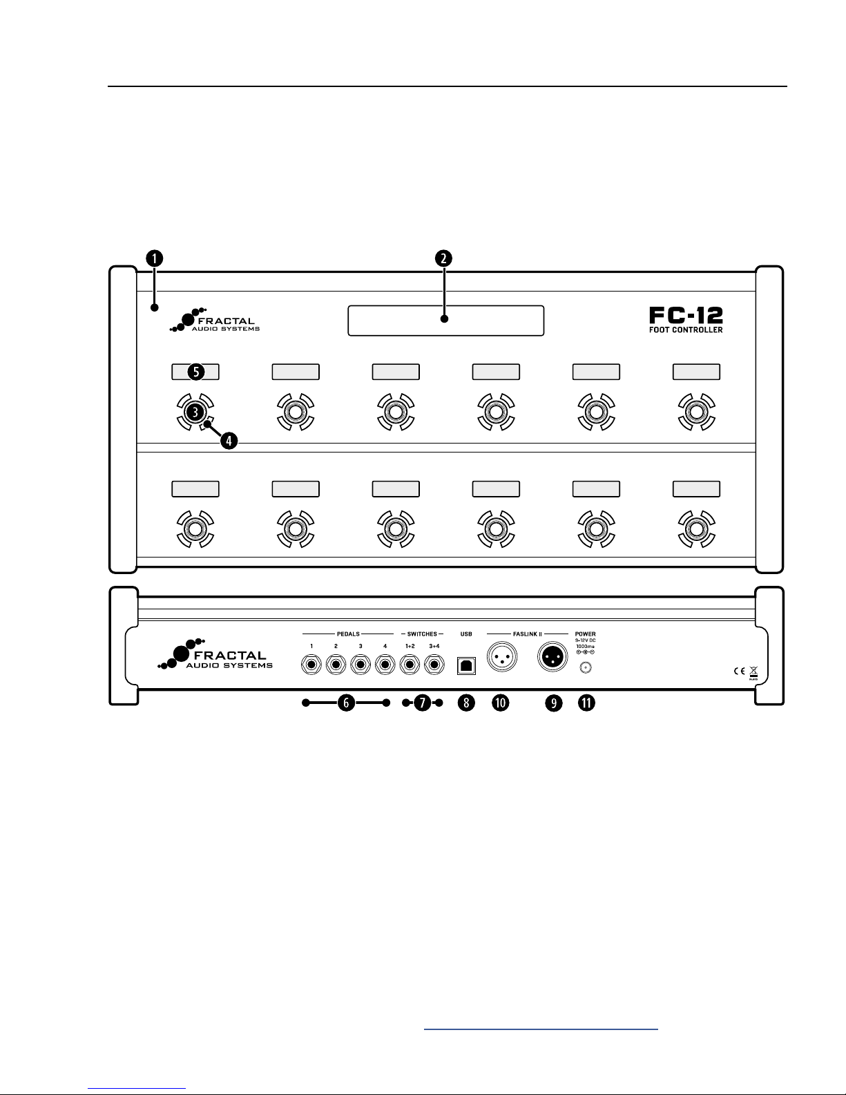
LED Ring — An LED ring around each switch changes color and brightness to help you navigate and operate
the FC. By default, the color shows the category of the switch’s Tap function. Presets, for example, are green,
banks are yellow, effects are blue, and so on. You can change the color for any category or any individual switch
( see p.23). The LED ring also changes its brightness to show the state of a switch, and each function has
its own built-in rules for how this works. For example, a scene switch is dimmed unless that scene is selected.
An effect switch is dim when the effect is bypassed and bright when the effect is engaged (or off altogether if
that effect is not found in the current preset.) You can change ring brightness on the Setup | Foot Controllers |
page (see p.41).
LCD Mini-Display — An LCD mini-display above each footswitch provides a useful label or indicator for
the switch. For example, a preset switch will default to showing the name of the preset that will load if
you activate that switch. Scene switches show scene names. For greater flexibility, each of the different
functions has its own list of mini-display “Label” options you can choose from, and you can even enter
custom text (though why anyone would want to label a footswitch “kebab” is beyond us.)
THE REAR PANEL
PEDAL Jacks — Four PEDAL jacks allow connecting up to four expression pedals or switches. The Fractal
Audio EV series pedals are perfect for this purpose, with linear action and long smooth travel. Pedals
connected to the FC are natively integrated with the Axe-Fx III modier system, without the need to congure
any parameters other than the modier source. Connect pedals using TRS-to-TRS cables, and be sure to
calibrate before use (see “Pedals & Switches” on p. 6).
SWITCH Jacks — Two SWITCH jacks allow connecting two switches each (1+2 and 3+4). Momentary and
latching switches are supported. Switches connected to the FC are natively integrated with the Axe-Fx III
modier system, without the need to congure any parameters other than the modier source. See “Pedals &
Switches” on p. 6 for more information.
USB Port — The USB port on the FC controller is reserved for future use. It is not required for rmware
updates, which are performed via the Axe-Fx III over FASLINK II. In fact, most features of the FC controller
are part of the Axe-Fx III itself, meaning that new Axe-Fx rmware can also add features to the FC.
FASLINK II port — (XLR-Male connector) The primary FASLINK II port (right XLR jack, looking at the
rear panel) allows connecting an Axe-Fx III. The FASLINK II connector provides power and two-way
communications over a single standard male-to-female XLR cable (such as a typical Mic cable).
a
FASLINK II (Daisy Chain Connector) — (XLR-Female connector) The secondary FASLINK II port (left jack,
looking at the rear panel) allows connecting up to three additional daisy-chained FC units. Connect additional
units using a standard XLR cable, but remember that only the rst unit in a daisy chain is powered by the
Axe-Fx III; additional units require 9–12V DC at their power inlets (see below). Daisy-chaining allows you to
extend footswitch “real estate” or to mirror different FC units to each other. (In comparison to “master/slave”
controllers of the past, mirroring keeps the switches and displays of multiple units completely in sync—in
effect offering a “dual master” scenario.) See “Daisy Chaining” on p. 8 for more information.
s
Power Inlet — The rst FC unit connected to an Axe-Fx III requires no AC power; the XLR cable powers the
unit and handles all communications. Any additional FC units connected in a daisy chain (p. 8) require
power from an AC adapter. Adapters ar available from https://shop.fractalaudio.com or you can use a third-
party adapter rated at 9–12V DC, 1000 ma, negative center, 2.5mm barrel. FASLINK II will not power the FC
Controller if the AC Adapter is connected—whether or not the adapter is plugged in.

5
3 SETTING UP
BASICS
This Guide assumes that you are using a single FC-6 or FC-12. For larger setups, see “Daisy Chaining” on p. 8.
CONNECT USING FASLINK II
Setting up a single FC unit is simple. Use a generic Male-to-Female XLR cable to connect the FASLINK™
II port of the Axe-Fx III to the FASLINK™ II port of the FC as shown in the diagram below. This connection
provides both power and 2-way communications—sending footswitch and pedal commands to the Axe-
Fx III, and sending the FC all required programming instructions, status updates, mini-display messages,
and more. The FC is even “hot swappable” meaning there is no need to power down the Axe-Fx III.
CONFIGURE THE AXE-FX III
No conguration is needed for the FC to function fully. However, we recommend loading the factory default
layouts and FC Conguration before rst use. To do so, please perform the following simple steps:
Page to the Reset page of the FC Controllers menu under SETUP.
Select the relevant entry for FC-6 or FC-12 and press ENTER.
If you are using a combination of different controllers in a daisy chain, it is probably best to load the
defaults for the unit in the chain, even though you will ultimately want to use custom layouts.
3 SETTING UP
Performing “Reset System Parameters” on the Axe-Fx III will erase ALL of the stored settings for
the FC Controller, setting them to blank. If this happens, you will need to re-load the Factory Default
Layouts & Settings as described above, or restore a backup of your Axe-Fx III System settings.
XLR Cable
FC-12 or FC-6
Axe-Fx III
Connect Axe-Fx III INs and OUTs
as you normally would (Audio, USB, etc.)
FASLINK II
Port (XLR Male)
FASLINK II Jack

6
3 SETTING UP
WHAT IS TRS? “TRS” stands for TIP-RING-SLEEVE and describes an endplug
or jack with three insulated contacts. Normal guitar cables are
TS (Tip-Sleeve) since they lack the ring which serves as a third
contact. The illustration at right shows both types.
Tip Sleeve
FIRST
SWIT
CH
FC EXT
SW
ITCH
JACK
SECOND
SWIT
CH
Ring
TIP
RING
PEDALS & SWITCHES
CONNECT AND CALIBRATE EXPRESSION PEDALS
Each FC Controller supports up to four expression pedals connected at the rear panel PEDAL jacks using
TRS-to-TRS cables. The Fractal Audio Systems EV pedal is perfect for this application, with true linear
response, smooth action and a long throw. (Third party pedals rated 10—100KΩ may also work.)
Page to the Remote page of the FC Controllers menu under SETUP.
If you have more than one FC controller connected, select the desired Target FC unit using the Aknob.
Ensure that Pedal Type is set to “CONTINUOUS” for the desired pedal (1–4).
Navigate to the Pedal Calibration function for the desired Pedal and press the ENTER button.
Follow the on-screen instructions to perform calibration. Watch the on-screen slider, which
shows the reading of the pedal as you move it. The slider should move over a large portion of
the range. Many brands of pedal will not reach the top, but all should reach the bottom.
Press ENTER when nished.
CONNECT A SWITCH AT A PEDAL JACK...
Instead of a pedal, you can alternately connect a single switch at any Pedal jack. Follow the instructions
above and simply set Type to “MOMENTARY” or “LATCHING” based on what you’re connecting and how
you want it to work. (If you’re not sure, check with the switch manufacturer or try both settings to see
which works better.) Calibration is not required. You can use a normal guitar cable (TS) for switches.
CONNECT EXTERNAL SWITCHES
Each external switch jack on the FC can host one or two external switches
of any type. Switches require no conguration or calibration.
For a single switch, use a normal guitar cable.
For two switches, use a ¼” TRS-to-dual ¼” TS “Y-cable” (aka an “insert cable”) where the tip
side is used for the rst switch and the ring side or the second, as illustrated below:
Tip Sleeve
Ring
TRS
Tip Sleeve
TS

7
3 SETTING UP
CONFIGURE THE AXE-FX III TO USE FC PEDALS AND SWITCHES
The Axe-Fx III features a powerful system of automation and remote control using
“. For example, a modier allows an expression pedal to operate a wah
or whammy. The Axe-Fx III Owner’s Manual covers modiers in detail.
The FC Controller is “plug-and-play” with the modier system, meaning that when you browse
through the list of modier Sources on the Axe-Fx III, you will discover four FC Pedal and four
FC External Switch options for each of four potential FC units (32 choices total!).
Most factory presets, however—and many other presets you might create, download, or purchase—will use
these FC sources directly. Instead, they will be set to use a “go-between” — a control node called an “External
Controller” — which sits between the modier and the pedal. External Controllers are more universal and user-
friendly because they can be congured globally. There are 16 numbered External Controllers on the Axe-Fx III. By
default, they are all set to “NONE” but we can easily map them to the pedals and switches of the FC Controller.
All Axe-Fx III factory presets are already set to use External 1 for operating various wah and
whammy effects (and more). As an example, let’s set External 1 to use FC#1 Pedal 1:
On the Axe-Fx III, open the External page of the MIDI/Remote menu under SETUP.
Locate the External Controller of your choice (External Control 1 for this example).
Turn the VALUE wheel to set External 1 to “FC#1 PEDAL 1”.
Continue setting other external controllers as desired and press EXIT when you’re nished.
The Axe-Fx III has two onboard pedal jacks, referred to in the MIDI/Remote menu
simply as “PEDAL 1” and “PEDAL 2”. Don’t confuse these with the entries for
FC pedals, which appear as “FC#1 PEDAL 1”, “FC#1 PEDAL 2” etc.
If for some reason you nd yourself without one or more of the pedals you normally
use with the FC, it will assume them to be in the TOE DOWN position. It is sometimes
best in this case set the corresponding External or Global Controller(s) on the Axe-Fx
III temporarily back to “NONE”, which is equivalent to the HEEL DOWN position.1
1 Once an external controller is set to “NONE” you can “park” the missing controller at 0% or 100%.
See your owner’s manual for more information about the External Controller Initial Value feature.
USE FC EXTERNAL SWITCHES FOR OTHER AXE-FX III GLOBAL FUNCTIONS
Aside from External Controllers (detailed above) the Axe-Fx III is equipped with dozens of other global functions
that can be controlled using FC Pedals and Switches. For example, the “Other” page of the MIDI/Remote menu
under SETUP contains global volume options for all inputs and outputs. Almost all of these global options can be
set to the FC pedal of your choice.
Be sure to use switches of the appropriate type for the function you have selected. For example, a Latching type
switch would be best for a channel or bypass control. Please refer to the Axe-Fx III manual for more about global
Remote functions.
The following example shows how to set the global Output 1 Volume to be controlled by FC#1 Pedal 2.
On the Axe-Fx III, page to the Other page of the MIDI/Remote menu under SETUP.
Locate the remote function of your choice (Output 1 Volume for this example).
Turn the VALUE wheel to select the desired FC pedal or switch (“FC#1 PEDAL 2” for this example).
You may wish to make other assignments on this or other menu pages.
Press HOME when nished.

8
3 SETTING UP
DAISY CHAINING
FC Controllers can be connected in series or “daisy-chained” to form a mega-controller of up to four units
operating as one. This allows access to more switches at once (reducing the need to switch layouts). You
can chain units of any type in any order, and any unit can load any of the eight layouts at any time.
Each FC supports up to four expression pedals and four external switches (see “Pedals & Switches” on p. 6).
CONNECT THE FIRST FC WITH FASLINK II
Setup begins just like when you use a single FC unit. Use a generic Male-to-Female XLR cable
to connect the FASLINK™ II port of the Axe-Fx III to the FASLINK™ II port of the rst FC. This
connection powers the unit and carries communication to and from the entire chain.
CONNECT ADDITIONAL FC UNITS WITH FASLINK II AND AC POWER
IMPORTANT: Only the rst unit connected directly to the Axe-Fx III will be powered by FASLINK II.
Each unit in a daisy chain after the rst requires local power via an AC Adapter rated 9–12V 1000 ma.
Compatible AC Adapters are available at https://shop.fractalaudio.com
FC-12 or FC-6 FC-12 or FC-6
Etc.
Up to
four units
in total.
Axe-Fx III
XLR Cable XLR Cable
Each daisy-chained FC
beyond the first requires
its own 9–12V DC Power supply.
Connect all INs and OUTs
as you normally would.
FASLINK II
Port (Male)
FASLINK II
Port (Male)
Power
Receptacle
FASLINK II
Port
FASLINK II
Port (Female)
CONFIGURATION
Daisy-chained FC units require no special conguration, though you will probably wish to design custom
layouts for use in this type of setup. In fact, you can specify which layout should be loaded upon startup for
each connected FC unit by using the options on the Devices page of the FC Controllers menu under SETUP.

9
3 SETTING UP
MIRRORING
Mirroring is a special setting that forces two or more daisy-chained FC units to remain perfectly
in sync. They show the same layouts, with all the same switches and switch states. Any change
to any mirrored unit is reflected instantly on the other mirrored unit(s). The usual scenario for
mirroring involves an artist on stage with a tech offstage who helps with switching.
To mirror one FC to another:
Change to the Devices page of the FC Controllers menu under SETUP.
Select the row for the FC unit that you want to mirror, then select the desired unit to mirror using the Dknob.
A note on pedals and switches: Connected expression pedals and switches are NOT mirrored,
since pedal jacks are named explicitly in modiers or controller assignments. For example,
“External 1” on your Axe-Fx might be set to “FC#1 PEDAL #1”. A preset using External 1
then will ONLY respond to that specic pedal and not the pedal 1 jack on a mirrored FC.
Fortunately, different presets, effects, or parameters can be assigned as desired to individual
pedal or switch jacks, so in one song, you might operate a wah, while during a different
song, your tech could do it for you offstage while you fly through the air on wires.
Any unit(s) can mirror any other unit(s), so be careful not to create a circular mirror
(1 mirrors 2, 2 mirrors 1). This will cause one or both FC units to
behave unpredictably until the problem is corrected.

10
3 SETTING UP
MIDI CONNECTIONS
You may have noticed that the FC is not a MIDI controller. It does not have MIDI ports. Combined with the Axe-Fx III,
however, it becomes part of a MIDI control system. Even without an FC, the Axe-Fx can serve as the centerpiece of
a MIDI rig, transmitting various messages from its MIDI OUT port. The FC controls the Axe-Fx and the Axe-Fx sends
MIDI messages. Don’t be mistaken and expect MIDI messages at the MIDI THRU port of the III; all MIDI messages
are generated by the Axe-Fx III at its MIDI OUT port.
Here’s a simple rig diagram showing how the FC and Axe-Fx III might be used to send MIDI to a connected amp,
which also passes messages on to a processor.
WHY NO MIDI PORTS ON THE FC? Early during the design of the new
foot controllers for our new flagship processor, we decided that the FC should be “lean
and mean.” Instead of crouching on the floor to delve through menus, FC owners would set up and operate the
unit using the color screen and interface of the mothership. Similarly, all of the “heavy lifting” would be done
by the Axe-Fx III, keeping the FC’s price down and extending the “client-server” concept of total integration. The
benets of this are great. Have you noticed, for instance, that as things change on your Axe-Fx III or in Axe-Edit,
the FC is updated automatically? With our new highly efcient FASLINK II protocol, the decision was complete.
MIDI had no place on the floor, and the Axe-Fx III would become the MIDI master!
XLR Cable
FC-12 or FC-6
Axe-Fx III
Audio and power connections not shown.
Connect all other INs and OUTs as you
normally would in your rig (Audio, USB, etc.)
FASLINK II
FASLINK II Port
MIDI OUT MIDI IN MIDI THRU
MIDI IN

11
4 LAYOUTS & SWITCHES
The FC is organized around Layouts. A layout is a set of up to 12 , each of which
includes one Tap and one Hold function. You can change layouts on the fly to access different “pages”
of switches1. For example, one layout might be used to select Presets or Scenes, while a different
layout operates the Looper. Any layout can be completely customized to serve your own needs. Layouts
even have their own names to make navigating easier. The Axe-Fx III provides eight layouts.
1 FC Layouts are not called “pages” to avoid confusion with pages in the Axe-Fx III.
THE MASTER LAYOUT MENU
Switching from one layout to another is the key to the versatility of the FC. There are many ways to
do this, but the built-in Master Layout Menu (“MLM” for short) will probably be the most popular.
The Master Layout Menu grants instant access to other layouts, one per footswitch.
To show the Master Layout Menu, rock your foot from heel to toe over both of the two right-most
footswitches on your FC, as shown in the following illustration of the “MLM Switch Combo”.
The Master Layout menu automatically assigns different layouts to different footswitches in order.
Footswitch 1 loads layout 1, Footswitch 2 loads layout 2, and so on. If your layouts have names, these will
be shown in the Mini-Displays. When you activate any switch to select a layout, it is loaded immediately.
The currently selected layout will be shown with a bright LED ring, while other options are dimmed. To exit
the MLM without changing the current layout, just select the bright switch for the current layout again.
If the lower right switch has a Tap function, it will not be activated by the MLM Switch Combo.
If the lower right switch has a Hold function, you can still easily execute the MLM Switch
Combo quickly, before the Hold function res. If the Hold function should re, the Master Layout
Menu will still be displayed. Learn more in “The Rules of Switch Timing” on p. 12.
When you design your own layouts, consider that the best Hold function for the lower right switch is
probably one that doesn’t change your sound if you accidentally re it while activating the MLM.
A good example would be “Reveal Hold Functions”, present in some of the default layouts.
A layout can also include Tap or Hold switches that change to other layouts without the MLM.
See Section 5: Footswitch Functions for more information on this and other switch functions.
MLM PAGING
Since there are eight layouts and the FC-6 has only 6 footswitches, the Master Layout Menu is split
into two pages. Just perform the “MLM Switch Combo” again — or use the MLM utlity function
(p. 32) — and the FC-6 will toggle between the two pages of the Master Layout Menu.

12
4 LAYOUTS & SWITCHES
You can change the duration of the Press and Hold Timeout on the page of the FC Controllers
menu under Setup. The default is 0.5 seconds. Make it if you nd that you are activating Hold
functions when you mean to activate Tap functions. Make it to re Hold functions sooner.
If you need tight timing from a Tap switch that has a Hold function, tap and release very quickly—
even a fraction of a second early, knowing that the change will occur as your foot comes up.
PRESS & HOLD LABELS
The Mini-Display for each switch normally shows the label for the Tap function. While any switch is depressed
— even for a normal “tap” — it changes to show the label of the Hold function, even if you don’t keep holidng
the switch down until its Hold function res! Meanwhile, a special “Reveal Hold” utility switch (see p.31)
can also be utilized to cause all mini-displays to persistently show the Hold functions for their switches.
time
time
time
TIMING FOR A TAP FUNCTION
WITH NO HOLD FUNCTION
TIMING FOR A TAP FUNCTION
WITH A HOLD FUNCTION
TIMING FOR ANY
HOLD FUNCTION
The Tap function res
at the moment the
footswitch is depressed.
The Tap function res when
you the switch, as
long as this happens before
the Press and Hold Timeout.
If not, the Hold function
eventually res...
When you hold a switch, its HOLD
function activates at the moment
the Press and Hold Timeout runs
out—whether or not the switch
has a Tap function. This does not
cause the Tap function to re.
TAP & HOLD FUNCTIONS
Every switch in every layout can be programmed with individual TAP and/or HOLD functions.
Tap functions — used throughout history for guitar effects and beyond — are best for changes that require tight
timing. For example, a tap switch set to SELECT SCENE is ideal to change the sound precisely as a solo begins.
Hold functions on the other hand, require a “long press” and are red after a brief
delay, so their timing is less precise. Hold switches are perfect for functions like
opening the Tuner, or accessing an alternate layout such as Looper Control.
THE RULES OF SWITCH TIMING
Like every guitar product in history with “hold” footswitches, the FC must follow rules for timing so it “knows”
whether you are trying to activate the Tap or the Hold. A switch with a Hold function must briefly delay the Tap
function until it can determine which one you are trying to activate. When this is the case, the tap is activated
when the switch is instead of when it is —unless you continue holding the switch past
the “Press and Hold Timeout” window. The following illustrations help explain switch ring and timing:

13
4 LAYOUTS & SWITCHES
EXAMPLE LAYOUTS
Two sample FC-12 layouts are shown below, each created by a different member of the FC beta testing team.
These are just two examples of the types of layouts that can be created using this flexible and powerful system.
Comp 1
Comp 1 A/B
“Preset” Layout
--
Phaser 1
Rotary 1
Per-Preset 2
Per-Preset 2
Reverb 1
“Shimmer” (Plex1)
Drive 2
--
Drive 1
DRV 1 Ch A/B
Per-Preset 1
Per-Preset 1
Delay 1
DLY 1 Ch A/B
Drive 1
--
Preset +1
“Looper” Layout
“Effects” Layout
“Looper” Layout
Tempo
Tuner
Tap Tempo
Tuner
Scene 2
--
S2 “Rhythm”
--
Scene 4
--
“Boost” (PEQ 1)
--
Scene 1
--
S1 “Clean”
--
Scene 3
--
S3 “Lead”
--
Preset -1
Reveal
Amp 1 A/B
--

14
4 LAYOUTS & SWITCHES
FACTORY DEFAULT LAYOUTS
Factory default settings for the FC include various pre-dened layouts: one for
selecting presets, one for changing scenes, one for the looper, and so on.
The following pages detail the factory default layouts for the FC-6 and FC-12.
The Axe-Fx III has so many capabilities, and there are so many different categories of player (bedroom, small
stage, touring professional, session player, etc) that there really is no such thing as an ideal layout—no “one-size-
ts-all” solution. We have therefore provided a set of layouts to demonstrate the very basic capabilities of the FC.
This gives beginners an easy way to select presets, change scenes, toggle effects, operate the looper and
more. Those who desire to make changes will nd it is very easy to create the perfect custom controller.
Here are a few things to know about the default layouts:
FC-6 and FC-12 have different default layouts. Be sure to follow the instructions under
“Congure the Axe-Fx III” on p. 5, especially if you are using an FC-6.
The Factory default layouts are designed to be simple.
The idea was that they should require almost no explanation, so someone using
the FC for the rst time could easily understand its broad capabilities.
Changing between the default layouts relies almost entirely on the Master Layout Menu (see p.11).
Except as noted, the default layouts do not have Hold functions.
Remember, you can change any switch on any layout to do anything you want. See
Section 5: Footswitch Functions for a complete guide to all functions.
Before either of the “Per-Preset” layouts will work, you’ll need to add custom switch
denitions to your presets. See “Per-Preset Functions” on p. 34
Layouts 7 and 8 are supported with simple tutorials on p. 44 and p. 46.
Other manuals for FC-6
1
This manual suits for next models
1
Table of contents
Other Fractal Accessories manuals