Frakco Aqua Magic Guardian Series User manual

Guardian Series
Consumer’s Filter Manual
Manufactured by:
Frakco, Inc.
606 East Dodge Street · Luverne, Minnesota 56156
www.frakco.com
12/10/20
Rev D.


Guardian General Specifications
Inlet/Outlet ................................................................................................................1”
Cycles .........................................................................................................................3
Valve Material............................................................................................................Noryl©
OPERATING PRESSURES
Minimum/Maximum......................................................................................40 - 80psi
Optimal Range................................................................................................40 - 60psi
*Pump output must meet or exceed backwash rate.
OPERATING TEMPERATURES
Minimum/Maximum......................................................................................40° - 110°F
Flow Rate
Guardian 150 Series.......................................................................................2.75 - 4.6 gpm
DIMENSIONS
Drain Line .......................................................................................................¾” or 1” NPT
Electrical Current Draw and Voltage..............................................................2.0A/120V
* Operating outside ofthe optimum pressure range may affect system functionality. Contact
your dealer for more information.
** Guardian Series not to be used with micro-biologically unsafe water sources.
Page 3

This owner’s manual is designed to assist owners and installers with the operation,
maintenance and installation of your new water filter. Detailed instructions on general
operating conditions, installation instructions, start-up, and programming are included. A
troubleshooting guide, service instructions and parts diagrams are also included to assist with
future needs.
Please contact the dealer who installed the system if you need professional assistance in
service of your water filter.
TABLE OF CONTENTS
General Specifications ....................................................................................3
Pre-Installation Checklist ................................................................................5
Start-up Instructions .......................................................................................5
Bypass Valve Operation ..................................................................................6
User Displays ..................................................................................................7
Installer Display Settings .................................................................................9
Parts Breakdown.............................................................................................10
Troubleshooting..............................................................................................19
Warranty.........................................................................................................20
Page 4

PRE-INSTALLATION CHECK LIST
(All electrical and plumbing should bedone in accordance toall local codes)
Guardian Series acceptable for indoor use only
Water Quality: Sand and sediment are often problems in rural water supplies. They may plug
the filter and restrict water flow through the media bed. Well and/or pump problems affecting
the operation of the filter and repairs are not covered under warranty.
Water Pressure: Aminimum of 40 pounds ofwater pressure (psi) isrequired for operation.
Maximum pressure is 80psi.
Water Temperature: Filter water temperature must not exceed 110°F or be subject tofreezing.
Existing Plumbing: Must be free from build-up. Ifplumbing isblocked, itmust be replaced or
additional equipment may be needed ahead offilter.
Electrical: All electrical connections must be connected per local codes. Acontinuous 110 volt
supply isrequired.
Drain Line: Filter should be located near drain. Do not use overhead drain lines as possible back
pressure may occur. Pipe size should be a minimum of¾” forthe drain.
Bypass Valves: Always allowfor installation of a bypass valve.
START-UP INSTRUCTIONS
*For optimal results, the filter media should be soaked for 12 hours prior to installation.
1. Complete all plumbing connections; inlet, outlet and drain line.
2. Place bypass inbypass position. Turn on main water supply and open a cold filtered
faucet toclear lines ofair or obstructions.
3. Plug unit into 120 volt outlet. Valve will move to service position once connection is
made.
4. Start a backwash cycle byholding the “REGEN” button down until valve movement is
heard.
5. Slowly open inlet valve onbypass until it is fully inopen position. Allow water to run to
the drain until clear.
6. Allow system to continue going through all the cycles.
7. Filter is ready for use after first regeneration cycle is complete.
Page 5

Backwash Frequency
Iron Applications
0.0 – 2.0 ppm Iron – Every 3rd day
1.0 – 4.0 ppm Iron – Every other day
4.0 – 8.0 ppm Iron – Every day
Specifications Filter
Tank
Size
Media
Cu. Ft.
Inlet/
Outlet
Max.
Service
Flow
GPM
Backwash
Rate
GPM
Guardian
10”x54”
1.5
1”
4.0
5.3
Guardian Pro
13”x54”
2.5
1”
7.0
10.0
Page 6

User Displays
General Operation
When the system is operating, one of four displays may be shown. Pressing NEXT
will alternate between the displays shown below.
.
User 1
Displays number of days to next regeneration.
User 2
Flow Rate. Displays present flow rate. Not applicable for Guardian Series Systems.
User 3
Displays total volume in gallons since last reset. Not applicable for Guardian Series
Systems.
User 4
Shows current time.
3
0
0
12:01
Page 7

•number of days between regeneration (1 to 28). Reference charts below.
RETURN TO
NORMAL MODE
STEP 1I
STEP 2I
STEP 3I
Installer Display Settings
STEP 1|- Press NEXT and simultaneously for 3 seconds. Press NEXT to
advance through the programming settings.
STEP 2|– Day Override: Sets the number of days between regenerations. Set Day
Override using or :
3
12:00am
Backwash Frequency
Iron Applications
0.0 – 2.0 ppm Iron – Every 3rd day
1.0 – 4.0 ppm Iron – Every other day
4.0 – 8.0 ppm Iron – Every day
STEP 3|– Regeneration Time (hour): Set the hour of day for regeneration
using or . AM/PM toggles after 12. The default time is 12:00 a.m. as
most water softeners regenerate at 2:00am. Regeneration should occur during a
period of low water usage. Press REGEN to return to previous step.
Page 8

Regeneration Mode
Typically a system is set to regenerate at a time of low water usage. An example of a time
with low water usage is when a household is asleep. If there is a demand for water when
the system is regenerating, untreated water will be used.
When the system begins to regenerate, the display will change to include information about
the step of the regeneration process and the time remaining for that step to be completed.
The system runs through the steps automatically and will reset itself to provide treated
water when the regeneration has been completed.
Manual Regeneration
Sometimes there is a need to regenerate the system sooner
than when the system calls for it, usually referred to as manual
regeneration. There may be a period of heavy water usage
because of guests or a heavy laundry day.
To initiate a manual regeneration at the preset delayed
regeneration time, press and release REGEN. The words "REGEN TODAY" will flash on the
display to indicate that the system will regenerate at the preset delayed regeneration time. If you
pressed REGEN in error, pressing the button again will cancel the request.
To initiate a manual regeneration immediately, press and hold REGEN for three seconds. The system will begin to
regenerate immediately. The request cannot be cancelled.
Power Loss
If the power goes out, the system will keep time for up to 8 hours or until the battery is depleted. If a power outage of more
than 8 hours occurs, the time of day will ash on and off which indicates the time of day should be reset. The system will
remember the rest. If a power outage lasts less than 8 hours and the time of day ashes on and off, the non rechargeable
battery should be replaced.
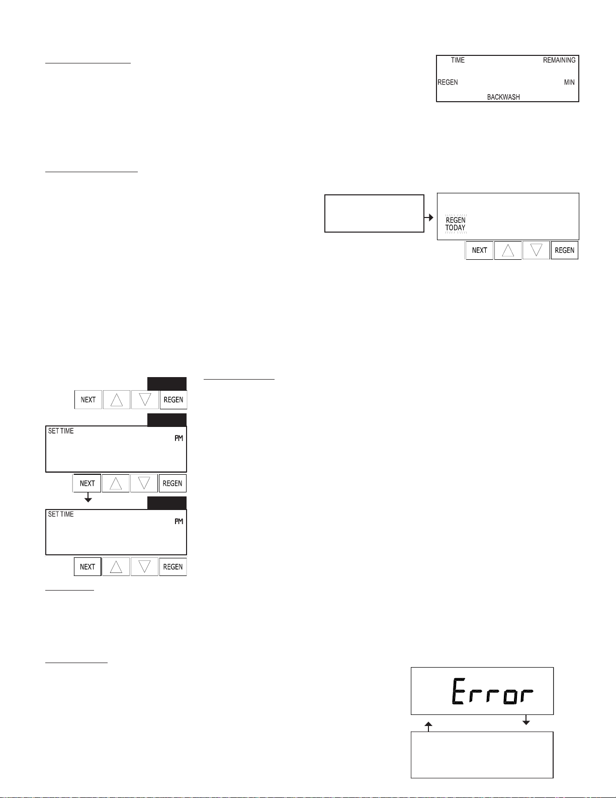
Error Message
If the word “ERROR” and a number are alternately ashing on the display
contact the OEM for help. This indicates that the valve was not able to function
properly.
Set Time of Day
The user can also set the time of day. Time of day should only need to be set after power
outages lasting more than 8 hours, if the battery has been depleted and a power outage
occurs, or when daylight saving time begins or ends. If a power outage lasting more than
8 hours occurs, the time of day will ash on and off which indicates the time of day
should be reset. If a power outage lasts less than 8 hours and the time of day ashes on
and off, the time of day should be reset and the battery replaced.
STEP 1U – Press and hold
STEP 2U - Current Time (hour): Set the hour of the day using or . AM/PM
toggles after 12. Press NEXT to go to step 3U.
STEP 3U - Current Time (minutes): Set the minutes of the day using or . Press
NEXT to exit Set Clock. Press REGEN to return to previous step.
STEP 1U
STEP 2U
STEP 3U
REGEN TODAY will
Flash if a regeneration
is expected “Tonight.”
8:00
until the time starts to change.
12:00
12:00
103
Page 9

Drawing No. Order No. Description Quantity
1 V3175EE-01 AM1 Front Cover Assembly 1
2 V3107-01 AM1 Motor 1
3 V3106-01 AM1 Drive Bracket & Spring Clip 1
4 V3408EE-04BOARD AM1 Thru/2EE PCB 5 Digit Replacement 1
5 V3110 AM1 Drive Gear 12x36 3
6 V3109 AM1 Drive Gear Cover 1
Not Shown V3186 AM1 AC Adapter 120V 1
V3186-01 AM1 AC Adapter Cord Only
Not Shown V3178 AM1 Drive Back Plate 1
Front Cover and Drive Assembly
1
4
6
5
3
2
AC Adapter U.S. International
Supply Voltage 120 V AC 230V AC
Supply Frequency 60 Hz 50 Hz
Output Voltage 12 V AC 12 V AC
Output Current 500 mA 500 mA
Refer to Control Valve Service Manual for other drawings and part numbers.
Relay Specications: 12V DC Relay with a coil resistance
not less than 80 ohms. If mounting relay under the cover
check for proper mounting dimensions on the backplate.
Wiring for Correct On/Off Operation
PC Board Relay Terminal Block Relay
RLY 1 Coil -
+ COM Coil +
Battery replacement is 3 volt
lithium coin cell type 2032.
Correct
Battery
Orientation
Battery Fully Seated
When replacing the battery, align
positives and push down to fully seat.
PC Board Relay
Terminal Block
Page 10

Drive Cap Assembly, Downflow Piston, Upflow Piston, Regenerant Piston and Spacer Stack Assembly
Drawing No. Order No. Description Quantity
1V3005-02 AM1 Spacer Stack Assembly 1
2 V3004 Drive Cap ASY 1
3Back Plate Refer to Programming and Cover Drawing Manual 1
4 V3011 AM1 Piston Downflow ASY
5 V3174 AM1 Regenerant Piston 1
6 V3135 O-ring 228 1
7 V3180 O-ring 337 1
8 V3105 O-ring 215 (Distributor Tube) 1
V3001 AM1 Body ASY Downflow
3
1
5
4a
6
2
7
8
1
Not Shown
Page 11
1

Injector Cap, Injector Screen, Injector, Plug and O-Ring
1
2
3
4
Drawing No. Order No. Description Quantity
1 V3176 INJECTOR CAP 1
2 V3152 O-RING 135 1
3V3177-01 INJECTOR SCREEN CAGE 1
41
V3010-1F AM1 INJECTOR ASY F BLUE
V3010-1H AM1 INJECTOR ASY H GREEN
Page 12

Refill Control and Check Valve
Drawing No. Order No. Description Quantity
1H4615 Elbow Locking Clip 1
2H4628 Elbow 3/8” Liquit 1
3V3163 0-ring 019 1
4 NeoOV15 15 MM Check Valve 1
5V4144-01CV Elbow 3/8 Liquit Asy w/RFC 1
1
3
4
2
5
Air
Flow
Proper check valve
orientation allows for air to
enter system during brine
draw cycle.
6
6ABPUS1 Brine Screen with Tube 1
Page 13

Drain Line – 3/4”
4
3
5
Water
Flow
Proper DLFC orientation
directs water ow towards
the washer face with
rounded edge.
2
Drawing No. Order No. Description Quantity
1H4615 Elbow Locking Clip 1
2
1
AM1 Drain Elbow ¾ Male
3V3163 O-ring 019 1
4V3159-01 AM1 DLFC Retainer ASY 1
5
One DLFC
must be
used if ¾
tting is
used
V3162-053 AM1 DLFC 5.3 gpm for ¾
V3162-100 AM1 DLFC 10.0 gpm for ¾
V3158-01
Page 14

Water Meter, Meter Plug and Mixing Valve
Drawing No. Order No. Description Quantity
1 V3151 AM1 Nut 1” QC 1
2 V3003* AM1 Meter ASY 1
3V3118-01 AM1 Turbine ASY 1
4 V3105 O-ring 215 1
5V3003-01 AM1 Meter Plug ASY Used With Guardian 1
3
4
5
1
2
*Order number V3003 includes V3118-01 AM1 Turbine ASY and V3105 O-ring 215.
THIS WATER METER SHOULD NOT BE USED AS THE PRIMARY MONITORING DEVICE FOR CRITICAL OR
HEALTH EFFECT APPLICATIONS.
NOTE: A water meter is not applicable for a GUARDIAN SERIES SYSTEM
Page 15

Bypass Valve
Drawing No. Order No. Description Quantity
1 V3151 AM1 Nut 1” Quick Connect 2
2 V3150 AM1 Split Ring 2
3 V3105 O-Ring 215 2
4 V3145 AM1 Bypass 1” Rotor 2
5 V3146 AM1 Bypass Cap 2
6 V3147 AM1 Bypass Handle 2
7 V3148 AM1 Bypass Rotor Seal Retainer 2
8 V3152 O-ring 135 2
9 V3155 O-ring 112 2
10 V3156 O-ring 214 2
(Not Shown) Order No. V3191-01, Description: AM1 Bypass Vertical Adapter Assembly
Order No. Description Quantity
V3151 AM1 Nut 1” Quick Connect 2
V3150 AM1 Split Ring 2
V3105 O-Ring 215 2
V3191 AM1 Bypass Vertical Adapter 2
Page 16

Service Spanner Wrench
(Order No. V3193-02)
Although no tools are necessary to assemble or disassemble the valve, the AM1 wrench (shown in various positions on the
valve) may be purchased to aid in assembly or disassembly.
Loosens Injector And
Bypass Caps
Loosens Drive Cap
Page 17

*Must be installed in downward
position
**Consult dealer for correct
media replacement
Item Quantity Part Number Description
1 1
2 1
3 1
4-5 1.5/2.5
6 1
7 1
8 1
91
10 1
CIOX-V1EEDTF
D601F
CL1054N
CL1354N
**
D1225-15
V3006
V3191-01CV
V4144-01CV
V3158-01
CIOX Valve
Distributor Tube
Mineral Tank
Mineral Tank
Filter Media
Air Disperser
Bypass Assembly
Elbow Assembly with CV*
Brine Elbow with CV
Drain Assembly
1
2
3
4-5
6
7
8
9
10
Page 18

TROUBLESHOOTING
Problem
1. Blank or unreadable LCD
display
2. Control valve stalled in
regeneration
3. Control valve regenerates
at wrong time of day
4. Odor/Color noticed on
outlet of filter
5. Reduction of water
pressure
Cause
A. Transformer unplugged
B. Defective transformer
C. No electric power at outlet
D. Check battery in valve
E. PC board is defective
A. Broken drive gear ordrive
cap assembly
B. Broken regenerant piston
C. Broken main piston
D. Motor notoperating
correctly
E. Defective transformer
F. No power tounit
A. Power outages
B. Time of day not set
correctly
C. Control valve is
programmed incorrectly
A. Perform water analysis
B. Determine if filter media
needs replacing
A. Determine if filter media
needs replacing
Solution
A. Connect to Power
B. Check to ensure 12 volt
motor, replace transformer
C. Repair outlet or switch to
working outlet
D. Replace battery if less than
3 volts
E. Replace PC Board
A. Replace drive gear or drive
cap assembly
B. Replace regenerant piston
C. Replace main piston
D. Replace motor
E. Check to ensure 12 volt
motor, replace transformer
F. Ensure working outlet
A. Reset time of day, replace
lithium coin type battery
on circuit board
B. Reset time of day
C. Check control valve
programming procedure
A. Increase regeneration
time.
a. Exceeding flow rate
specification
B. Replace filter media
A. Replace filter media
Page 19

FILTER WARRANTY
This quality FRAKCO water filter is designed and built to provide many years of satisfactory
performance under normal use. FRAKCO, INC. pledges to the original owner that for 54 months,
commencing ___________________ every part, component, and/or a portion of the above
described water filter proven to be defective due to workmanship and/or materials will be
replaced or repaired. FRAKCO also pledges that the fiberglass media tank is covered under this
warranty for 5 years if owned by the original purchaser. Out pledge does not apply if the
damage is caused by defective installation; water pressure in excess of 80 lbs. per square inch;
water temperature in excess of 110° F.; misuse; unauthorized alterations; freezing; accident;
fire; neglect; or damage caused by shipping.
To obtain service under this warranty, notify FRAKCO, INC in writing of any defects in
workmanship within thirty (30) days of the appearance of such defects. Such written notice
must include the date of purchase, the part number, and a description of the defect. Upon
receiving such notice and determining that the defect is covered by this warranty, FRAKCO, INC.
will replace or repair the defective item. Replacement of a defective item will be at FRAKCO’S
factory in Luverne, MN, and the purchaser must ship the defective item at its own expense to
FRAKCO’S factory. Replacement items will be shipped by FRAKCO F.O.B. Luverne, Minnesota,
with a shipping carton furnished. In the event certain models or colors of the replacement item
are out of stock, FRAKCO, INC. may, after notifying the purchaser, furnish another model or
color of the replacement item. The factory will not pay for service charges and will not perform
any repair or service functions other than at its home office.
Please follow the enclosed instructions and local codes in installing your water filter and send
the warranty registration to the manufacturer within 30 days of installation. Failure to do so will
void this warranty. Nothing in the warranty may be construed as involving the factory in the
relationship between Dealer and Owner.
This warranty gives the purchaser specific legal rights. The purchase may also have implied
warranty rights. In the event of a problem with warranty service or performance, the purchaser
may be able to go to a Small Claims Court, a State Court, or a Federal District Court. This
warranty complies with the 1975 Federal Warranty Law.
Model No. ______________Serial No. _______________Date Installed _______________
Dealer ________________________Address __________________________________
Page 20
This manual suits for next models
3
Table of contents
Popular Water Filtration System manuals by other brands

Hayward
Hayward Salt & Swim 3C owner's manual

CALEFFI
CALEFFI 5495 SEP4 Installation, commissioning and servicing instructions

Good Water Warehouse
Good Water Warehouse GOLDLINE-50 Installation & service guide

LaserLiner
LaserLiner AirBreeze 360 manual

3P Technik
3P Technik 3P Rustico instruction sheet

Philips
Philips AC4141 Specifications