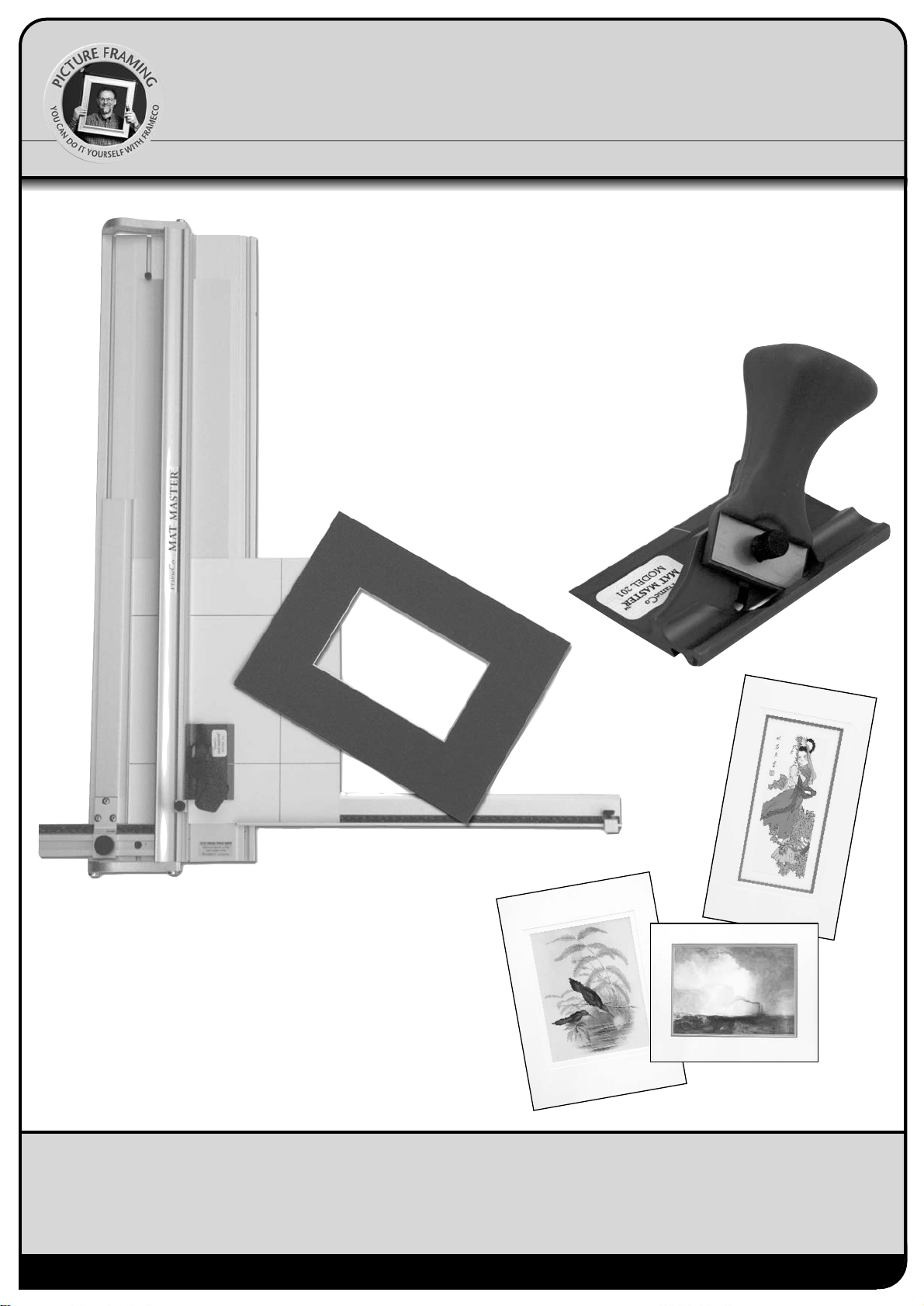
perfect bevels everytime
fig. 4 Anti-clockwise to lower blade
fig. 5 Ideal blade depth
Changing & Adjusting the Blade Depth
Cutting Position
Over & Under Cuts
fig. 41
fig. 42
Changes to the Depth Adjustment Screw moves the depth stop..
ie the blade travels further. It does not actually lower the blade.
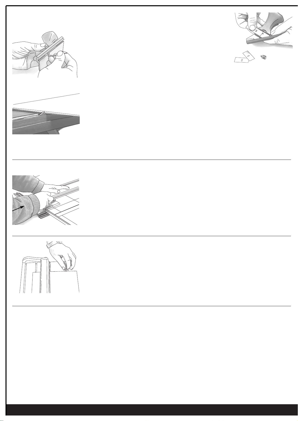
1. The blade is held in place with one central screw.
2. Release and remove the used blade by removing the central screw.
3 The blades are packed in packs of 5 and can be used both ends.
4. Fit a new blade into the handle with the sharp edge down.
5. Replace the central screw.
The cutting depth of the blade can be adjusted using the allen key supplied.
Rotate the depth adjustment screw, located in the base of the cutting head, anticlockwise
to lower the blade (see fig. 4). One full turn lowers the blade by approximately 0.1mm.
The blade should only just protrude through the mount board for a clean and easy cut.
Measure the depth against a sample of the mount board as shown in fig. 5.
Note 1: When using the bevel cutter on your machines always have a slip mat in position under
the mount being cut. Use a piece of standard mount board cut to size.
Note 2: Hooks - If the blade is set to low it may flex and cause a small “hook” at the start of the
cut. Set the depth correctly - see fig.5.
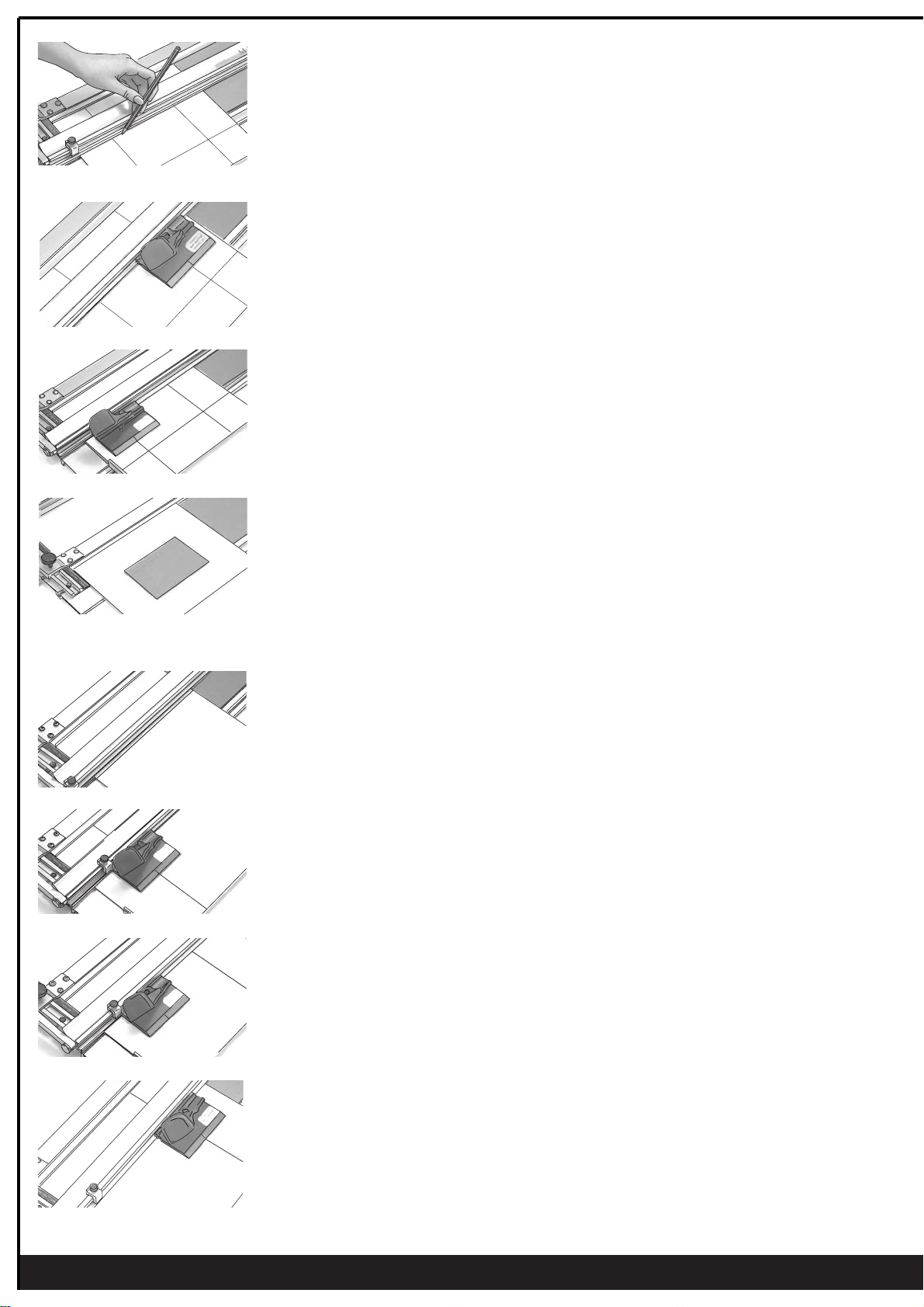
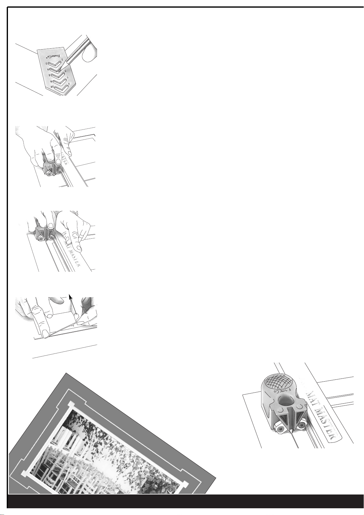
Cutting a new mount takes very little effort.
The way you hold and push the cutting head is important as it effects the quality of the cut.
To start cutting, push the blade firmly into the mount board so that the blade penetrates all the
way through the mount board. Before starting to cut, lower your arm, so that you are cutting
along the line, rather than pushing downwards (see fig. 41).
If you find that cutting is hard work review your cutting position and lower your arm a little
to make it easier.
Always practice on a spare board before making your first cut, or after changing the blade depth.
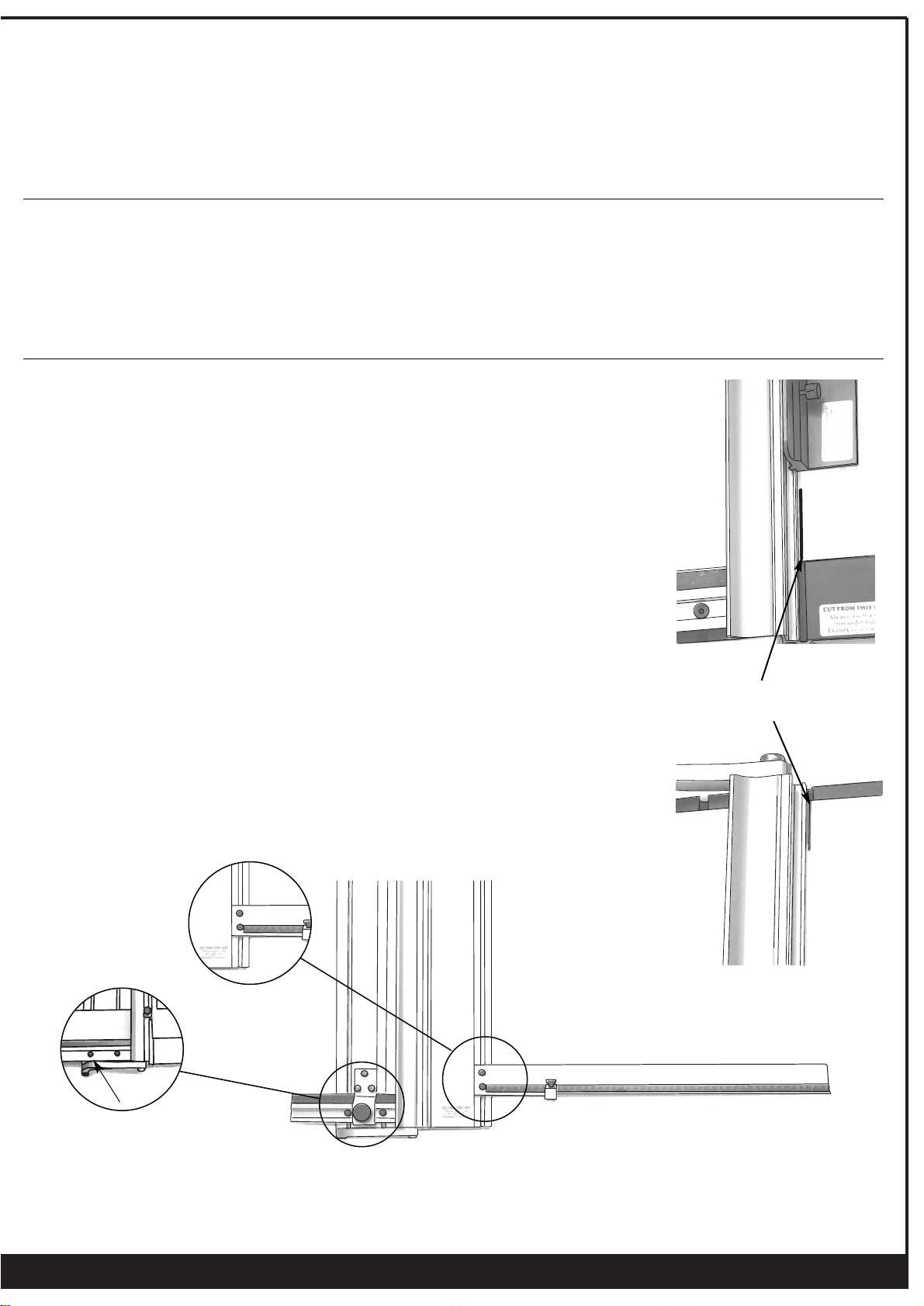
Do not use self healing plastic mats under the cutting rail. Strips of standard mount board are
best suited as slip mats. An ideal size is
Make sure you are not cutting into old cuts in the slip mat as these may cause the blade to cut
away from the rail. The slip mat stop (see fig. 42) can be located into any slot so that different
sized piece of mount board can be used under the cutting rail.
The stop can be located in any one of the grooves in the base board.
Over Cuts
If the blade depth is adjusted correctly, any over cuts will be due to you travelling too far past the finishing line or starting too early
before the line. Adjust your starting and stopping position to eliminate these over cuts.
Under Cuts
If the drop out does not fall out after cutting your mount, do not push it out as this may tear the corners. Take a spare blade and
extend the cut so that the centre piece falls out. The ideal is to have the centre fall out each time with no over cuts and no
undercuts. As with over cuts, if you find that the mat is undercut then simply adjust your starting and stopping position relative to
the start and stop lines ie. start a little earlier and finish a little further. You have to find the ideal start and stop position relative to
the size pencil you use (2H is ideal), and how you draw the line (holding the pencil close against the rail is ideal).
7
fig. 40
Slip Mats