Francis Searchlights FR560RC Installation instructions

User Instruction & Installation Manual
FR560 Remote Control 1 & 2 Kilowatt
Tungsten Halogen Searchlight
Product Reference Number:
A7132 –FR560RC 1Kw 115/240v
A7133 –FR560RC 2Kw 115/240v
Manufacturer’s details: Distributor details:
Manual Part Number: C27635
2.11.17 Issue: 2
Francis Searchlights Ltd
Union Road, Bolton
Lancashire, BL2 2HJ, UK
Tel: +44 (0) 1204 558960
Fax: +44 (0) 1204 558979
http://www.francis.co.uk
E-mail: sales@francis.co.uk

1 - Introduction
It is imperative that this manual is read carefully and understood before
installing your equipment. For your future reference please keep this
manual in a safe place.
Thank you for specifying a product from the Francis Searchlights range. All Francis products
are designed to give complete customer satisfaction and are manufactured to the highest
engineering standards in order to ensure optimum performance and service life.
The Francis FR range combines features proven over many years service in the most
hazardous conditions in both marine and land installations.
In order to prolong the life and performance of your product, we recommend that you only
specify Francis Searchlights spare parts. This will also ensure that any warranties on your
equipment will not be invalidated. Information on spares ordering and parts is provided in this
manual.
Should you ever need to contact Francis Searchlights Ltd. regarding your equipment, please
quote the Product Serial Number at all times.
Back To Top

2 - Safety Precautions
The following instructions must be adhered to, in order to ensure a safe working environment
and the safety of the user.
Note: When unpacking or manoeuvring the searchlight into its fixing position, suitable
lifting points must be used in order to prevent damage to the equipment or personal
injury.
Prevent rain, snow, condensation and water droplets from contacting the lamp as this may
cause bulb failure and possible shattering;
Quartz halogen bulbs run with a high internal pressure in excess of atmospheric. Whilst the
construction is inherently strong, there is a slight risk of the bulb shattering;
Never look directly into an illuminated searchlight as this may cause severe damage to
eyesight. If it is necessary to inspect a lamp whilst in operation, always wear suitable
protective goggles;
Should it be necessary to examine the lamp with the front bezel removed, always use a
protective shield and wear goggles to ensure a safe working environment;
Never attempt to clean a lamp whilst in use;
Searchlights get hot. Never touch the unit when lit and always allow 15 to 20 minutes for
cooling down after turning the searchlight off;
Never place anything on or cover the searchlight when in use;
Ensure the lamp has cooled sufficiently before removal;
If undue force appears necessary to remove the lamp, the equipment should be inspected
by a competent person or contact the manufacturer;
When breaking a lamp for disposal, care must be taken to ensure the glass fragments are
safely contained. This operation must be performed out of doors in free air. In all
circumstances refer to the lamp manufacturers instructions packed with the lamp;
Due to the vast range of lamps available it may appear possible that more powerful lamps
can be used in the equipment than for which it was designed. Even when the unit will
physically accept a higher wattage or voltage lamp, this substitution is not recommended
and is dangerous. This action will also void any warranties on the equipment.
Always refer to the lamp manufacturer’s technical data when dealing with lamps.
Back To Top

3 - Technical Information
This product has been designed to operate in accordance with the product specification. The
FR560RC searchlight has the following features:
All marine grade materials and fixings;
Parabolic glass reflector;
Powder coated & Stove enamel paint finish;
385° horizontal rotation;
Vertical movement +30° to -35˚;
Variable speed 1-23°/sec (Pan), 1-8°/sec (Tilt);
RS485 connectivity & auto home positioning;
Remote focus facility;
Internal self-regulating heater. (Optional);
Toughened front glass;
The FR560RC 1Kw searchlight also performs to the following optical data:
1000 Watt T/H 1000 Watt T/H
Supply voltage 110/115v 220/240v
Peak Beam Candlepower 2,450,000 Lux 2,450,000 Lux
Range 1550 metres 1550 metres
Divergence 5° 5
Operational temperature with heater -50°C (-20without) -50°C (-20without)
The FR560RC 2Kw searchlight also performs to the following optical data:
2000 Watt T/H 2000 Watt T/H
Supply voltage 110/115v 220/240v
Peak Beam Candlepower 4,121,000 Lux 4,121,000 Lux
Range 2030 metres 2030 metres
Divergence 5.5° 5.5
Operational temperature with heater -50°C (-20without) -50°C (-20without)
In order that the searchlight operates correctly it is imperative that competent personnel are
responsible for the installation, operation and servicing of this equipment. Failure to adhere to
this advice may cause premature failure or incorrect operation of the searchlight, which may
damage the equipment or cause personal injury.
Back To Top

4 - Unpacking and Installation Instructions
The following instructions should be read and fully understood prior to installing the equipment
to ensure that the correct procedures are followed, and all safety precautions are observed.
Note: If the equipment has been in storage for a considerable amount of time, it is
advisable to conduct a routine maintenance check on all parts before installation.
Safety Precautions
This equipment should not be connected to an electrical supply before being installed.
Installation procedures should be adhered to in order to ensure a safe working environment
and reduce the risk of damage or personal injury.
Preparing the Mounting Position
Mark out and drill the fixing holes through the deck (refer to drawing C21501). If anti-vibration
mounts are to be fitted, the fixing holes for the mounts should also be marked out and drilled.
Prior to manoeuvring the searchlight into its’ fixing position, the AV mounts should be fitted to
the base. When in the desired position, bolt the searchlight firmly down. On an uneven surface
it may be necessary to use a suitable sealant such as silicone, in order to ensure a
weatherproofed joint.
Back To Top

5 - Electrical Installation
Note: ~
When the main power is first applied to the searchlight, the searchlight will carry out a
self-test, it will Pan to the left limit and Tilt down to the limit, once this is complete, the
searchlight will then move to the centre and horizontal, during this please do not try and
operate the searchlight while this test is being carried out. Once the searchlight is back
at centre the searchlight can then be operated normally, by pressing the Panel button on
the control panel.
For safety purposes, only competent personnel should perform the electrical installation. All
equipment should be installed to current Electrical Regulations and Standards.
In order to obtain the maximum light output from the searchlight, it is essential that the full
operating voltage of the lamp fitted be applied to the lampholder contacts.
Method of Electrical Connection
1) Disconnect the supply before working on the electrical system;
2) The searchlight must be connected to a fused electrical supply, using suitably sized cable;
3) If the searchlight is located a considerable distance from the supply, provision must be
made in the cable size in order to overcome the voltage drop.
The following table below indicates the maximum length of cable to be used for the AC
supply cable:
Searchlight
115v 1Kw
115v 2Kw
230v 1Kw
230v 2Kw
Cable Size (mm²)
Distance Max
Distance Max
Distance Max
Distance Max
1.5
17 MTRS
8 MTRS
68 MTRS
37 MTRS
2.5
28 MTRS
14 MTRS
111 MTRS
60 MTRS
4
44 MTRS
22 MTRS
176 MTRS
96 MTRS
6
69 MTRS
34 MTRS
275 MTRS
150 MTRS
10
115 MTRS
57 MTRS
460 MTRS
250 MTRS
4) Whenever possible cable terminations should be made below deck and with approved
terminal devices;
5) If a spare auxiliary fuse or circuit breaker is not available, one of the correct type and rating
should be fitted and connected to a positive supply. It is advisable to locate a bus bar or
main connection and avoid any direct connection to the supply:
6) For 110/220v AC products, the following colour coding system should be used for the
customer supply cable:
Brown - Live
Blue - Negative
Green/Yellow - Earth
Note: This equipment must be earthed.

Installation Guidelines
A typical installation and connection routine for the FR560RC searchlight is as follows:
Referring to wiring diagram C27426, a supply is fed to the junction box, which then provides a
common feed to the motor gearbox, searchlight and joystick panel.
The searchlight has been pre-wired with 3 meters of cable from the motor gearbox to junction
box provided. The searchlight head is pre-wired along with the connecting cable to the motor
gearbox.
Cables required to be connected by the customer: -
2 pair twisted 0.22mm 100 ohm screened cable from the joystick panel to the junction box.
Supply cable to the junction box.
Back To Top

6 - Operating Instructions
This equipment is designed for use out of doors, in free air. Never place anything on or cover
the searchlight when in use as this may present a hazard.
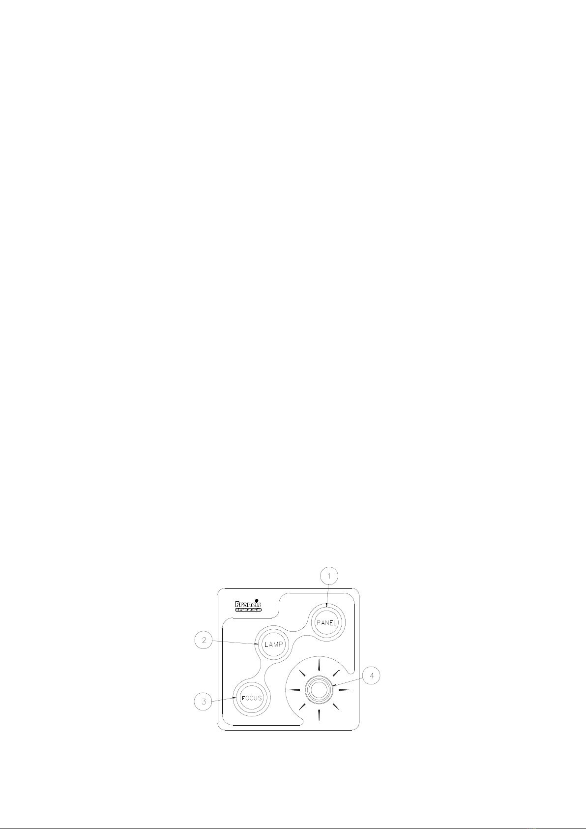
The searchlight can be remotely positioned via the joystick control panel, with the facility for
movement up, down, left and right. (See Fig 1 below for aid to instructions)
To operate the panel, press panel button (1), the button will light up & the joystick (4) is now
operational. To switch the lamp on or off press the lamp button (2)
The speed of movement depends on the more pressure applied to the joystick (4) the faster the
searchlight moves. When in the desired position the joystick should be released so that it
returns to dead centre.
On remote focus models the beam of the searchlight can be adjusted to give a variety of beam
types. Using the focus button (3) on the joystick panel, the desired beam can be achieved for
any particular application. The beam will move continuously through ‘spot’ to ‘flood’. In order to
fix the beam type, simply release the focus button at the desired position.
To return the searchlight to Factory set auto home position (forward and horizontal) simply
switch off the joystick panel using the panel button (1) and then press the lamp button (2), the
searchlight will then move to the pre-programed home position.
To set a new Home position, move the searchlight to the desired home position, switch off the
panel (1), move the joystick to the downward position ↓ and simultaneously press the Lamp
button (2).
There is the option for added slave panels, the slave panel has all the features of the main
control panel i.e. joystick, focus and on/off.
When the lamp is switched on, this will illuminate the Lamp button (1) on both the Main & Slave
Control panel, also when the Focus button (3) is pressed, both Focus buttons will be
illuminated.
The brightness of the panel can be increased or decreased by holding the panel switch (1)
down and moving the joystick left and right, left to decrease right to increase.
Fig 1

When fitting the lamp:
-Always isolate the equipment from the supply when inserting a lamp;
-Ensure the circuit is suitably fused;
-Ensure the lamp is of the correct power rating and type;
-Check lampholder is in good condition. If the contacts show any sign of corrosion, replace
the lampholder;
-Check the lampholder is in a good dry condition. Never allow water to collect in the lamp
fitting or come into contact with the lamp.
To fit the lamp:
-Unfasten the 5 front latches and remove the front bezel assembly, leave to hang from the
safety chain;
-For easier access the spill ring may be removed by undoing the fasteners;
-Position the two pins above the holes in the lampholder;
-Gently push the lamp into the lampholder;
-Replace the light spill ring and front bezel assembly, ensuring the latches are secure.
Testing
Upon correct installation and connection to an electrical supply, the equipment can be tested in
order to ensure its’ correct performance. A competent person with some knowledge of electrical
equipment must carry out this work.
Equipment required: Multi-meter with leads
Ammeter
Using the equation P=VI, the approximate power output of the equipment can be calculated in
the following way:
-Using the multi-meter, take a voltage reading across terminals 3 & 7 in the searchlight;
-Using the ammeter, take an amp reading from the live cable to the lamp;
-Multiply these figures together to give an approximate wattage (Power output).
For example:
Using a 240v 1000w Tungsten halogen lamp:
Voltage reading = 240v; Amps reading = 4 amps
Therefore, Wattage = 240 x 4 = 960 watts
Back To Top

FBUS SPEED CONTROL ASSEMBLY DETAILS
MAINS CONNECTORS
L Live.
N Neutral
E Earth
TILT CONNECTOR
MR Tilt Motor Red Wire (+)
MB Tilt Motor Black Wire (-)
ER Tilt Encoder Red Wire (5V). (Voyager Brown Wire)
EG Tilt Encoder Green Wire (Phase A Output) (Voyager Yellow Wire)
EW Tilt Encoder White Wire (Phase B Output)
0V Tilt Encoder Black Wire (Voyager Blue Wire)
Tilt Limit Switch Common Black Wire
UL Tilt up Limit Switch Orange Wire
DL Tilt down Limit Switch Blue Wire
PAN CONNECTOR
MR Pan Motor Red Wire (+)
MB Pan Motor Black Wire (-)
ER Pan Encoder Red Wire (5V)
EG Pan Encoder Green Wire (Phase A Output)
EW Pan Encoder White Wire (Phase B Output)
0V Pan Encoder Black & Pan Limit Switch Common
CL Pan Clockwise Limit Switch Orange Wire (As viewed looking down on lamp)
AL Pan Anticlockwise Limit Switch (As viewed looking down on lamp)
HEAD CONNECTOR
0 0V Common for Heater & Focus (If Searchlight has an igniter terminal is not used)
H Heater Active High Output
F Focus Motor Active High Output
S Focus position potentiometer.
FBUS CONNECTOR
0 OV out to Joystick Panels
T Line Terminate (Connect to + for terminate)
+ FBUS Data +
- FBUS DATA -
24 24V Supply out to joystick panels
24 VOLT INPUT
- Negative
+ Positive
LAMP RELAY
Relay input
Relay output

FBUS Speed Control Board

CONNECTIONS TO FBUS JOYSTICK CONTROL PANEL
FBUS CONNECTOR
0 OV Supply Input
T Line Terminate (Connect to + for terminate)
+ FBUS + RS485 Data In/Out
- FBUS - RS485 Data In/Out
24 +24V Supply Input
JOYSTICK CONNECTOR
BK Joystick Black Wire
Y Joystick Yellow Wire
BL Joystick Blue Wire
R Joystick Red Wire
FBUS JOYSTICK CONTROL BOARD

FBUS ADDRESS SWITCHES
OVERVIEW
FBUS uses two types of address switch. One type is rotary, and the value selected is the value
shown on the dial. The other type is rows of switches whose operation is described below: -
The switches all operate in the same manner producing a binary value with the highest binary
value to the left and the lowest value to the right. The values for each switch are listed below: -
SPEED CONTROL CARD LAMP ADDRESS
SWITCH NUMBER VALUE
SWITCH 4 16
SWITCH 5 8
SWITCH 6 4
SWITCH 7 2
SWITCH 8 1
STANDARD CONTROL PANEL –LAMP ADDRESS
SWITCH NUMBER VALUE
SWITCH 1 16
SWITCH 2 8
SWITCH 3 4
SWITCH 4 2
SWITCH 5 1
STANDARD CONTROL PANEL –PANEL ADDRESS
SWITCH NUMBER VALUE
SWITCH 1 8
SWITCH 2 4
SWITCH 3 2
SWITCH 4 1
Switching a switch to on, adds the binary value relating to that switch to the address value.
With all switches off the value is zero.

EXAMPLES
Standard control panel –panel address set to 5
Switch 1 = Off
Switch 2 = On (Value 4 added to address)
Switch 3 = Off
Switch 4 = On (Value 1 added to address)
4 + 1 = 5
Speed control card - lamp address set to 11
Switch 4 = Off
Switch 5 = On (Value 8 added to address)
Switch 6 = Off
Switch 7 = On (Value 2 added to address)
Switch 8 = On (Value 1 added to address)
8 + 2 + 1 = 11
ADDRESSING SYSTEM
The addressing system is very simple. Every lamp must have a unique address. The
addresses should be sequential and should start from zero. If there were three lamps in a
system the addresses should be set to 0, 1 and 2.
Control panel –panel addresses use the same system being sequential and start from zero.
It is essential that all lamp have a unique address with no duplication.
It is essential that all panels have a unique address with no duplication however note that
lamps and panels can be the same address. For example, on a system with two panels and
two lamps, the panel addresses will be 0 and 1 and the lamps addresses will be 0 and 1.
Control panel lamp addresses are defined by the system configuration. If two panels are used
to control the same lamp they must still have individual panel addresses but the lamp
addresses can be set to the same address value as the lamp which is to be controlled. Any
number of panels can control the same lamp.

FBUS DATA PROTOCOL
OVERVIEW
The Francis bus (FBUS) is a custom communication protocol based on
RS485 two wire bi directional communication hardware. The system provides
a simple bi-directional link between lamps and lamp control panels. The
system allows given panels to communicate with different lamps and also
allows a number of panels to communicate with the same lamp.
DETAILED DESCRIPTION
The FBUS system runs at 38.4K Baud. This low data rate facilitates longer
cable runs and complements the fairly small amount of data transfer required
whilst still providing a fast response. The data frame is 11 bits with 9 data bits,
one start and one stop bit. A simple error detection system is employed which
is described in detail later. Data is sent LSB first.
To prevent data collisions the system uses a polling technique. Lamp number
0 is the default bus master and controls timing of all communications by
polling other units connected to the bus. If lamp 0 is not operating or powered
down, lamp 1 automatically becomes the bus master as will lamp 2 if lamp 1
is not operating.
The system differentiates between address and data values by setting data bit
8 high for an address. Panel 2 address would therefore be sent as hex 102 or
binary 100000010. The lamps and panels use different address ranges with
panels being addresses 0-15 and lamp addresses starting at 16 and going up
to 56. A lamp whose address was set to 0 on the address switches will
actually be address 16 and would be transmitted as hex 110 or binary
100010000.
If lamp 0 is active this becomes the bus master and sequentially transmits the
full address range. No other units will transmit until they receive their address.
Each address is followed by a 1mS dead period where the master switches
from transmit to receive and monitors the bus for activity. If activity is present
the master will not transmit the next address until 1mS after bus activity
ceases. After the full panel address range has been sent (addresses 0-15) the
master starts to send lamp addresses.
These operate slightly differently in that, if more than three successive
addresses do not illicit a response, the bus master will assume the last lamp
has been polled and re starts the data cycle by reverting to panel address 0.
When a remote panel receives its address, it will send data if it has any to
send, if not, no data will be sent. Lamps operate differently in that they will
always send data after they have seen their address on the bus.
Panels can send data to any lamp therefore they transmit a modified lamp
address value prior to the lamp command(s). The modified address is
received by lamps and, if it matches their own address, the command(s)
which follow will be received and processed.
A detailed description of panel and lamp data follows.

PANEL TRANSMITTED DATA
Panels only send data when there is data to be sent i.e. there has been
activity at the panel which must be sent to a given lamp. If there is no data to
be sent, a panel will not transmit. The amount of data a panel sends will
depend upon the amount of activity at the panel and can be 2 to 10 bytes. The
commands described below are sent after a panel receives its address which
it uses as indication that it has a transmit time slot. Before any commands are
sent the panel must define which lamp the data pertains to. This is achieved
by preceding the command with a lamp address. Note that bit 7 is not set
when a panel defines the lamp to which it is to transmit. Lamps recognise the
address and receive data when the address matches their own. To send
commands to lamp number 2 a panel would precede the lamp command(s)
with the address value Hex 2, Binary 000000010. It is important to note that
multiple commands must be sent in numerical order i.e. a command with
value 01 must be sent before a command with 06 etc.
Panel transmit commands are listed below; -
DATA_PAN_JOYSTICK (Hex 01)
This is a two-byte command and must be immediately followed by another
byte whose value determines the lamps direction and speed. The value is
centred on 128 and has a range of 128 +/- 64. A value of 130 will make the
lamp rotate slowly clockwise. Increasing the value will make the lamp move
faster. A value of 126 will make the lamp rotate slowly anticlockwise.
Decreasing the value will make the lamp move faster. Transmitting values 01
then C0 would make the lamp pan clockwise at full speed.
DATA_TILT_JOYSTICK (Hex 02)
This is a two-byte command and must be immediately followed by another
byte whose value determines the lamps direction and speed. The value is
centred on 128 and has a range of 128 +/- 64. A value of 130 will make the
lamp point upwards slowly. Increasing the value will make the lamp move
faster. A value of 126 will make the lamp move down slowly. Decreasing the
value will make the lamp move faster. Sending values 02 then C0 would make
the lamp tilt up at full speed.
DATA_LAMP_BUTTON (Hex 0A)
This is a single byte command. The same command is sent to switch the lamp
on or off. This command must only be sent once for each press of the button.
Sending again will switch the lamp again. Basically, if the lamp was off,
sending this value will switch it on. If the lamp was on, sending this value will
switch it off. This technique is employed to facilitate simultaneous lamp control
from a number of different panels. Basically, what is sent is just information
that the lamp on off button has been pressed. How the lamp reacts to this
depends on the lamps current status. Most of the other lamp button
commands operate in a similar manner except the focus button. Confirmation
that the command has been received can be obtained by reading the lamp
status byte described below.

DATA_FOCUS_BUTTON (Hex 0B)
This is a single byte command. When the lamp receives this, it will run the
focus motor as long as the command remains. A panel will send this
command so long as the focus button is pressed.
DATA_HOME_BUTTON (Hex 0C)
This is s single byte command. A lamp receiving this will automatically move
to the pre-set home position. The command does not need to be maintained
while the lamp moves to home.
DATA_RECORD_BUTTON (Hex 0D)
This is a single byte command. The first time a lamp receives this command it
will enter record mode and start monitoring all movement and lamp switching
information. Recording will continue until the command is received again
when it will stop recording. As with most of the button commands it is
essential this command is just sent once. Confirmation that the command has
been received can be obtained by reading the lamp status byte described
below.
DATA_PLAY_BUTTON (Hex 0E)
This is a single byte command. The first time this is received a lamp will start
playing back any movement / lamp switching activities which were recorded
using the record function above. This will continue until the command is
received again or the lamp receives a move command
(DATA_PAN_JOYSTICK or DATA_TILT_JOYSTICK).
DATA_HOME_LP (Hex 0F)
This is a single byte command which activates when the home button is
pressed and held for 5 seconds (Home Long Press). This is used to store a
new home position. A lamp receiving this command will store the current
position as the value to move to when the home button is pressed normally.
Note that a lamp can only receive up to 10 bytes at a time. A panels transmit
sequence is the modified receiving lamp address followed by data commands
then the CRC. The CRC is formed by the sum of all the commands + the lamp
address value –note however that the address value used in the CRC is the
unmodified value (Bit 7 clear).
DATA_PAN_POSITION (Hex 18)
This is a three-byte command. Following the DATA_PAN_POSITION
command two data bytes specify the position to which the lamp must move.
The bearing resolution is 0.1 degrees. The value is sent LSB first with the first
byte representing the lower position command bits. The MSB (sent last) lower
4 bits represents the remaining value. The position value is centred on 2048
(Binary 1000 0000 0000) so a value of 2048 would make the lamp move to
the dead ahead position. An increasing value represents a clockwise motion
with a resolution of 0.1 degrees. A value of 2058 would therefore represent 1
degree clockwise (2058 = 2048 + 10 –but resolution is 0.1 degrees so a
value 10 = 1 degree). Values below 2048 represent anticlockwise motion so a
value of 1048 would represent an angle 100 degrees anticlockwise of centre.

DATA_TILT_POSITION (Hex 19)
This is a three-byte command. Following the DATA_TILT_POSITION
command two data bytes specify the position to which the lamp must move.
The bearing resolution is 0.1 degrees. The value is sent LSB first with the first
byte representing the lower position command bits. The MSB (sent last) lower
4 bits represents the remaining value. The position value is centred on 2048
(Binary 1000 0000 0000) so a value of 2048 would make the lamp move to
the dead ahead position. An increasing value represents tilting up with a
resolution of 0.1 degrees. A value of 2058 would therefore represent 1 degree
up from dead ahead (2058 = 2048 + 10 –but resolution is 0.1 degrees so a
value 10 = 1 degree). Values below 2048 represent tilting down so a value of
1748 would represent an angle 30 degrees down from centre.
LAMP TRANSMITTED DATA
A given lamp after it receives its normal address (Hex 110 to Hex 138) will
always send the following data in this specific order. The lamp must transmit
its first data byte (pan position) within 1mS of receiving its standard address
and the gaps between successive bytes must be less than 1mS.
Lamp TX Byte 1 –Pan position LSB
Lamp TX Byte 2 –Pan position MSB
Lamp TX Byte 3 –Tilt position LSB
Lamp TX Byte 4 –Tilt position MSB
Lamp TX Byte 5 –Lamp status
Lamp TX Byte 6 –CRC
Each byte is described below
Pan Position
This is a 12-bit value with lamp pointing straight ahead being a value of 2048
and the value increasing as the lamp rotates clockwise as viewed from above.
The system has a resolution of 0.1 degrees so 90 degrees clockwise from
centre would be a value of 2948 (2048 + 900).
Tilt position
This is a 12-bit value with lamp horizontal being a value of 2048 and the value
increasing as the lamp beam points up. This has a resolution of 0.1 degrees.
Lamp Status
This is an 8-bit value with each bit representing a specific status aspect. The
bit functions are listed below; -
Bit 0 - Lamp on
Bit 1 - Pan Limit reached
Bit 2 - Tilt Limit reached
Bit 3 - Lamp Recording
Bit 4 - Lamp Playing
Bit 5 - Lamp Overheated
Bit 6 - Lamp moving to home
Bit 7 - Reserved
The bits are all true logic so if the lamp is switched on, bit 0 will be high.

CRC
The CRC is a simple data checking system. Basically, this is just the sum of
the lamps address and bytes above. The value is radix to 8 bits. If the lamp
address was 0 (bus address value 16) and the pan and tilt were both at centre
and the lamp was switched on and all other status bits were 0 the values
would be Hex 110, 80, 80, 01. This would give a CRC value of 11.
Each lamp connected to the bus will always send the data sequence above
after it detects its address on the bus. This is basically broadcast information
which will be picked up by any panel whose lamp address value matches the
currently transmitting lamp address. In this way a panel, which can access
more than one lamp, will always update to reflect the status of the currently
selected lamp more or less instantly.
EXTERNAL INTERFACE TO LAMPS
Interfacing to FBUS is simple. Any external interface must act as a slave and
only send data when given an address slot. The address of an external
interface can be any of the panel addresses providing these are not in use by
other panels connected to the bus. To receive data from a lamp simply wait
for the specific lamps address to be present on the bus then load the next six
bytes which will comprise the lamps transmitted data as described above. A
detailed description of transmitting and receiving is described below.
TRANSMITTING TO A LAMP
Basically, any sending device mimics a control panel. The full range of panel
transmit commands, as described above, can be employed. Data can be sent
to any lamp on the system. Two transmit examples are listed below.
EXAMPLE 1
Sending a lamp on/off command using panel 0 address and sending to lamp
address 0. Note that the lamp will change switched state each time this
command is sent therefore this should only be sent once.
1. Wait for panel address 0 (Hex 100) to be received from the bus.
2. Transmit lamp 0 address (Hex 110) within 1mS. Lamp address 0 is
physical address 16 (Hex 10). When a panel sends to a lamp bit 8 is
set (hex 100).
3. Send DATA_LAMP_BUTTON Command (Hex value 0A) within 1mS.
4. Send CRC value, in this case Hex 110 + Hex 0A = 11A after radix to
8 bits = 1A. This completes the transmission
EXAMPLE 2
Sending a half speed pan clockwise command using panel 1 address and
sending to lamp address 6. –Note that in this example the lamp will continue
to pan as long as the command is repeated.
1. Wait for panel address 1 (Hex 101) to be transmitted by the master.
2. Transmit lamp 6 address (Hex 16) within 1mS. Lamp address 6 is
physical address 22 (Hex 16).
3. Send DATA_PAN_JOYSTICK Command (Hex value 01) within 1mS.
4. Send pan value half speed = 128 + (64/2) = Hex A0 within 1mS.
This manual suits for next models
2
Table of contents
Other Francis Searchlights Marine Lighting manuals