manuals.online logo
Brands
  1. Home
  2. •
  3. Brands
  4. •
  5. Franke
  6. •
  7. Water Dispenser
  8. •
  9. Franke KEM8SCP User manual

Franke KEM8SCP User manual

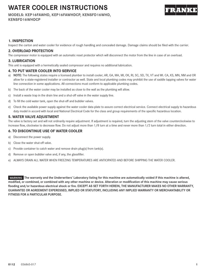
10112 036865-009
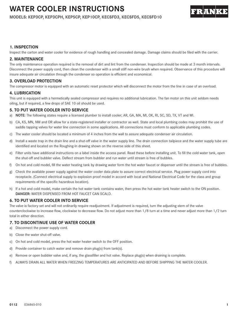
MODULAR FOUNTAINS & WATER COOLERS
MODELS: kEM8SCPM, kEM8SCEE, kEMSCPM, kEDRF-3801, kEDRF-3801HF,
kEDF-3801, kEMSSLPM, kEDF-3701, kEM8SBPM, kEM8SBEE, kEMSBPM,
kEDRF-3601, kEDRF-3501HF, kEDF-3601
A. INSPECTION
Inspect the cartons and various components for evidence of rough handling and concealed damage. Damage claims should be filed with the carrier.
B. MAINTENANCE (FOUNTAINS WITH COOLINg UNIT)
The only maintenance required is the removal of dirt and lint from the condenser. Inspection should be made at 3 month intervals. Remove the grille and
clean the condenser with a vacuum attachment.
C. OVERLOAD PROTECTION (FOUNTAINS WITH COOLINg UNIT)
The compressor motor is equipped with an automatic reset protector which will disconnect the motor from the line in case of overload.
D. LUBRICATION (FOUNTAINS WITH COOLINg UNIT)
This unit is equipped with a hermetically sealed compressor, no additional lubrication is required. The fan motor installed on this unit seldom needs oiling; if
required, a few drops of SAE 10 oil should be used.
E. TO DISCONTINUE USE OF FOUNTAINS WITH COOLINg UNITS
Drain cooler when removed from service. (1) Remove grille, (2) Close supply valve, (3) Provide container to catch water, and remove drain plug,
(4) Remove bubbler.
F. INSTALLATION, PLUMBINg & ELECTRICAL CONNECTIONS
1. NOTE: The following states require a licensed plumber to install cooler, AR, GA, MA, MI, OK, RI, SC, SD, TX, VT AND WI. CA, KS, MN, NM and OR allow
for a state-registered installer or contractor as well. State and local plumbing codes may prohibit the use of saddle tapping valves for water line
connection in some applications. All connections must conform to applicable plumbing codes.
2. Plumbing and electrical (if required) rough-in and wall opening should be prepared as shown on Roughing-in drawing (On new plumbing installation, a
strainer, not furnished, is recommended).
3. Insert frame or frames into wall opening and secure to studs. NOTE: FRONT FLANGE OF FRAME(S) MUST BE FLUSH WITH THE FINISHED
WALL LINE SURFACE.
4. Attach cradle mounting angles to frame flange with 4 screws provided. Slide unit mounting cradle into frame and secure in place with 4 screws
provided. (Cradle is used only when cooling unit is to be installed.) NOTE: Bottom flange on cradle is to be behind frame front flange.
5. Slide cooling unit onto cradle. For filter models refer to the cooling unit instructions for installation details. NOTE: Periodic access will be
needed to replace the filter; place in location shown on “Rough-In and Dimensional Drawing” for easy access.
6. It is recommended that flexible conduit be used to supply power to the cooling unit and fountain(s) when required. Check the electric current available.
Type and voltage must be the same as listed on the unit data plate.
7. Place the upper panel in place on the frame top angle and fasten with 2 screws, provided, at bottom.
8. Use two 1/4" bolts and partially screw into the two holes located in the center of the pattern of six holes.
9. Place fountain so the two keyholes in the rear are over the two bolts. This should support the fountain. Using remaining four 1/4" bolts, fasten fountain
securely in place. Then tighten the two bolts used to support the fountain.
10. Complete plumbing to fountain. Check for leaks on new plumbing installations, run water through the bubbler(s) until water taste satisfactory.
11. On electronic eye models, place and then hold hand approximately 3" (76 mm) from the sensor to actuate the solenoid valve. After approximately 30
seconds run time, the sensor will automatically shut off the solenoid valve. To reactivate, move hand away for an instant and then again place it in front
of the sensor. Repeat until the stream from the bubbler is free of bubbles.
12. To adjust the beam range of the sensor:
a) Shut off the water and power supply. Remove the rear bottom plate.
b) Unscrew the sensor bracket screws from the front mounting plate and remove the sensor unit and bracket sufficiently to gain access to the
bracket front face. Remove the foam strip between the two lenses in order to uncover the sensor adjusting screw.
c) The screw can be turned a maximum of 3/4 turns. Turn screw counterclockwise to decrease range. The sensor has an adjustable range of 24"
(610 mm) to 48" (1219 mm). It is factory set at 27" (686 mm). There is a non-adjustable on-time delay of 1.5 seconds to prevent nuisance
actuation of the solenoid valve should someone walk by. After draining, the water will shut off immediately after walking away. Maximum run time
is 30 seconds.
NOTE: Walls with a reflective finish, i.e., ceramic tile., across from the sensor may cause false actuation no matter what the sensor adjustment is for
distance. Therefore, do not install the unit in such an area or dull the surface of the wall so it will not reflect light. The bubbler valve will not actuate if objects
cover over the electronic eye lens, i.e., necktie or hand.
The warranty and the Underwriters’ Laboratory listing for this machine are automatically voided if this machine is altered, modified,
or combined with any other machine or device. Alteration or modification of this machine may cause serious flooding and/or hazardous electrical
shock or fire. THE WARRANTY AND THE UNDERWRITERS’ LABORATORY LISTING FOR THIS MACHINE ARE AUTOMATICALLY VOIDED IF THIS
MACHINE IS ALTERED, MODIFIED, OR COMBINED WITH ANY OTHER MACHINE OR DEVICE. ALTERATION OR MODIFICATION OF THIS MACHINE
MAY CAUSE SERIOUS FLOODING AND/OR HAZARDOUS ELECTRICAL SHOCK OR FIRE.
WARNINg
2036865-009 0112 30112 036865-009
FOUNTAINS & WATER COOLERS
MODELS: kEM8SCPM, kEM8SCEE, kEMSCPM, kEDRF-3801,
kEDRF-3801HF, kEDF-3801
3. 2 [51] DIA. PUSHBUTTON OR TWO 9/16 [14] DIA.
ELECTRICAL EYES, PUSH BUTTON SHOWN.
NOTES:
*1. RECOMMENDED ADULT HEIGHT INSTALLATION SHOWN.
ADJUST VERTICAL DIMENSIONS AS REQUIRED TO COMPLY
WITH FEDERAL, STATE AND LOCAL CODES.
2. STOP VALUE NOT PROVIDED WITH UNIT.
WALL OPENING
FLOOR LINE
38 3/4
[984]
THIRD ANGLE PROJECTION ROUGHING-IN
AND
DIMENSIONAL DRAWING
6. ALL DIMENSIONS ARE IN INCHES.
DIMENSIONS IN BRACKETS [ ] ARE IN MILLIMETERS.
4. KEM(F)8SCPM AND KEM(F)8SCEE ONLY.
5. PLAIN (NO LOUVERS) - KEMSCPM ONLY.
1 1/4 X 11 1/2 NPT
WASTE CONNECTION
19
[483]
13 27/32
[352]
9 3/8
[238]
3 3/4
[95]
37 3/8
[949]
*
31 3/8
[797]
*
FLOOR LINE
FACE OF FRAME IS FUSH
WITH FINISHED WALL LINE
BOLT FRAMES TOGETHER WITH SPACERS BETWEEN,
USING 1/4 -20 X 2 1/4 BOLTS, NUTS AND WASHERS
PROVIDED. SECURE FRAME ASSY. IN WALL
OPENING WITH FACE OF FRAME FLUSH WITH
FINISHED WALL.
HANG PANEL OVER TOP FLANGE OF WALL
FRAME. INSTALL SCREWS THRU BOTTOM
OF PANEL INTO FRAME.
DRINKING FOUNTAIN, MOUNT
TO UPPER FRONT PANEL AND
FRAME WITH (6) BOLTS.
17 1/2
[445]
27 5/32*
[690] 17 1/4
[438]
38 1/2
[978]
19 3/4
[502]
2”[51] DIA
PUSHBUTTON
42*
[1067]
40*
[1016]
36*
[914]
34*
[864]
27*
[686]
FOUNTAIN
WATER INLET
3/8 [9.5] O.D.
TUBING
1/2 [13]
28 27/32*
[733]
34 27/32
[885]
*
3 7/8
[98]
33*
[838] 26 5/8
[676]
*
18 1/4
[464]
3 7/8
[98]
9 7/8
[251]
9 7/8
[251]
39 1/2
[1003]
FOUNTAIN
WATER INLET
DRINKING FOUNTAIN, MOUNT
TO UPPER FRONT PANEL AND
FRAME WITH (6) BOLTS.
ROUGHING-IN AND DIMENSIONAL DRAWING WALL OPENING & ASSEMBLY
FOUNTAIN MODELS
MODELS: kEMSSLPM, kEDF-3701
ROUGHING-IN AND DIMENSIONAL DRAWING
LOCATION TO
MOUNT FILTER
WITH PROVIDED CLIP.
COOLING UNIT
WATER INLET
1/4 O.D. TUBE.
WALL OPENING & ASSEMBLY
WALL OPENING
FLOOR LINE
38 3/4
[984]
THIRD ANGLE PROJECTION ROUGHING-IN
AND
DIMENSIONAL DRAWING
3. 2 [51] DIA. PUSHBUTTON OR TWO 9/16 [14] DIA.
ELECTRONIC EYES, PUSHBUTTON SHOWN.
NOTES:
*1. RECOMMENDED ADULT HEIGHT INSTALLATION SHOWN.
ADJUST VERTICAL DIMENSIONS AS REQUIRED TO COMPLY
WITH FEDERAL, STATE AND LOCAL CODES.
2. STOP VALUE NOT PROVIDED WITH UNIT.
6. ALL DIMENSIONS ARE IN INCHES.
DIMENSIONS IN BRACKETS [ ] ARE IN MILLIMETERS.
4. KEM(F)8SCPM AND KEM(F)8SCEE ONLY.
5. PLAIN (NO LOUVERS) - KEMSCPM ONLY.
1 1/4 X 11 1/2 NPT
WASTE CONNECTION
TO BUBBLER
VALVE
WASTE
19
[483]
13 27/32
[352]
9 3/8
[238]
3 3/4
[95]
37 3/8*
[949]
31 3/8*
[797]
21 15/16*
[557]
11 5/16 [287]
(SEE NOTE 4)
FLOOR LINE
FACE OF FRAME IS FUSH
WITH FINISHED WALL LINE.
ELECTRICAL CONNECTION
(SEE NOTE 4)
FINISHED WALL LINE
SECURE CRADLE MOUNTING ANGLE TO
FRAME FLANGE WITH (4) SCREWS PROVIDED.
DO NOT TIGHTEN SCREWS. SLIDE CRADLE
BETWEEN ANGLES AND ATTACH TO ANGLES
WITH (4) SCREWS PROVIDED. FRONT FLANGE
OF CRADLE IS BEHIND FRAME. TIGHTEN
ALL SCREWS.
BOLT FRAMES TOGETHER WITH SPACERS BETWEEN,
USING 1/4 -20 X 2 1/4 BOLTS, NUTS AND WASHERS PROVIDED
SECURE FRAME ASSY. IN WALL OPENING WITH FACE
OF FRAME FLUSH WITH FINISHED WALL.
HANG PANEL OVER TOP FLANGE OF WALL
FRAME. INSTALL SCREWS THRU BOTTOM
OF PANEL INTO FRAME.
DRINKING FOUNTAIN, MOUNT
TO UPPER FRONT PANEL AND
FRAME WITH (6) BOLTS.
CRADLE: SEE CRADLE
MOUNTING INSTRUTIONS
DETAIL.
COOLING UNIT, MOUNT
INSIDE CRADLE.
LOWER FRONT PANELS MOUNT TO FRAME
WITH SCREWS THRU BOTTOM.
SEE NOTE 5
SIDE OF FRAME
DRINKING FOUNTAIN, MOUNT
TO UPPER FRONT PANEL AND
FRAME WITH (6) BOLTS.
CRADLE MOUNTING
INSTRUCTIONS DETAIL
* 4 1/8
[105]
40
[1016] 39 3/4
[1010]
4 5/8
[117]
38 1/2
[978]
19 3/4
[502]
SEE
NOTE 3
42*
[1067]
40*
[1016]
36*
[914]
34*
[864]
27*
[686]
FOUNTAIN
WATER INLET
3/8 [9.5] O.D.
TUBING
ELECTRICAL
CONNECTION
(SEE NOTE 4)
1 3/8 [35]
1/2 [13]
3 1/2 [89]
28 27/32*
[733]
34 27/32
[885]
*
3 7/8
[98]
33*
[838] 6 1/2
[165]
5 3/8
[137]
40 3/4
[1035]
3 7/8
[98]
7 3/4
[197]
REF.
9 7/8
[251]
9 7/8
[251]
39 1/2
[1003]
FOUNTAIN
WATER INLET
WATER INLET
AND OUTLET
ELECTRICAL JUNCTION BOX ON
ELECTRONIC EYE MODEL ONLY.
036865-009 0112
Franke Kindred Canada Limited
1000 Franke Kindred Road
Midland, ON L4R 4K9
CANADA
Tel. 1-866-687-7465
Fax 1-800-361-8408
www.franke-commercial.com
FOUNTAINS & WATER COOLERS
MODELS: kEM8SBPM, kEM8SBEE, kEMSBPM, kEDRF-3601,
kEDRF-3501HF, kEDF-3601
ROUGHING-IN AND DIMENSIONAL DRAWING
FOUNTAIN
WATER INLET
3/8 [9.5] O.D.
TUBING
COOLING UNIT
WATER INLET
1/4 O.D. TUBE
19
[483]
9 3/8
[238]
1 3/8 [35]
27*
[686]
21 15/16*
[557]
11 5/16 [287]
(SEE NOTE 4)
FINISHED WALL LINE
TO BUBBLER
VALVE
WALL OPENING & ASSEMBLY
WALL MTG FRAME, SECURES INTO WALL
FACE OF FRAME IS FLUSH WITH FINISHED
WALL.
WALL OPENING
CRADLE: SEE CRADLE
MOUNTING INSTRUCTIONS
DETAIL.
LOWER FRONT PANEL. MOUNT TO FRAME
WITH SCREWS THRU BOTTOM.
(SEE NOTE 5)
SECURE CRADLE MOUNTING ANGLE TO
FRAME FLANGE WITH (4) SCREWS PROVIDED.
DO NOT TIGHTEN SCREWS. SLIDE CRADLE
BETWEEN ANGLES AND ATTACH TO ANGLES
WITH (4) SCREWS PROVIDED. FRONT FLANGE
OF CRADLE IS BEHIND FRAME. TIGHTEN
ALL SCREWS.
40
[1016]
39 3/4
[1010]
4 5/8
[117]
*
19
[483]
THIRD ANGLE PROJECTION ROUGHING-IN
AND
DIMENSIONAL DRAWING
SIDE OF FRAME
DRINKING FOUNTAIN, MOUNT
TO UPPER FRONT PANEL AND
FRAME WITH (6) BOLTS.
COOLING UNIT, MOUNT
INSIDE CRADLE
HANG PANEL OVER TOP FLANGE OF WALL
FRAME. INSTALL SCREWS THRU BOTTOM
OF PANEL INTO FRAME.
FLOOR LINE
18 3/4
[476]
1 1/4 X 11 1/2 NPT
WASTE CONNECTION
ELECTRICAL JUNCTION BOX ON
ELECTRONIC EYE MODEL ONLY
WATER INLET
AND OUTLET
FOUNTAIN
WATER INLET
SEE
NOTE 3
ELECTRICAL CONNECTION
(SEE NOTE 4)
LOCATION TO
MOUNT FILTER
WITH PROVIDED CLIP
FLOOR LINE
FACE OF FRAME IS FLUSH
WITH FINISHED WALL LINE
34*
[864]
36*
[914] 28 27/32*
[733]
7 3/4
[197]
REF.
19 3/4
[502]
9 7/8
[251]
3 7/8
[98]
40 3/4
[1035]
* 4 1/8
[105]
5 3/8
[137]
6 1/2
[165]
31 3/8*
[797]
ELECTRICAL
CONNECTION
(SEE NOTE 4)
1/2 [13]
3 1/2 [89]
WASTE
3. 2 [51] DIA. PUSHBUTTON OR TWO 9/16 [14] DIA.
ELECTRONIC EYES, PUSHBUTTON SHOWN.
NOTES:
*1. RECOMMENDED ADULT HEIGHT INSTALLATION SHOWN.
ADJUST VERTICAL DIMENSIONS AS REQUIRED TO COMPLY
WITH FEDERAL, STATE AND LOCAL CODES.
2. STOP VALUE NOT PROVIDED WITH UNIT.
6. ALL DIMENSIONS ARE IN INCHES.
DIMENSIONS IN BRACKETS [ ] ARE IN MILLIMETERS.
4. KEM(F)8SBPM AND KEM(F)8SBEE ONLY.
5. PLAIN (NO LOUVERS) - KEMSBPM ONLY.
CRADLE MOUNTING
INSTRUCTIONS DETAIL

This manual suits for next models

16

Other Franke Water Dispenser manuals

Franke HT-300 User manual

Franke

Franke HT-300 User manual

Franke KEP8M User manual

Franke

Franke KEP8M User manual

Franke KEP AC-EBF Series User manual

Franke

Franke KEP AC-EBF Series User manual

Franke FRC05 Instruction sheet

Franke

Franke FRC05 Instruction sheet

Franke KEP16FAWHD User manual

Franke

Franke KEP16FAWHD User manual

Franke KEP AC-EBF-STN Series User manual

Franke

Franke KEP AC-EBF-STN Series User manual

Franke Little Butler LB2200 Series User manual

Franke

Franke Little Butler LB2200 Series User manual

Franke KEP3CP User manual

Franke

Franke KEP3CP User manual

Franke KEP8FA User manual

Franke

Franke KEP8FA User manual

Franke Little Butler LB1000 User manual

Franke

Franke Little Butler LB1000 User manual

Popular Water Dispenser manuals by other brands

US Water Systems FNLT-100-HY owner's manual

US Water Systems

US Water Systems FNLT-100-HY owner's manual

Hellenbrand ProMate DMT Series Consumers manual

Hellenbrand

Hellenbrand ProMate DMT Series Consumers manual

BRIO 300 Series Setup manual

BRIO

BRIO 300 Series Setup manual

ECG MHZ 270 SD instruction manual

ECG

ECG MHZ 270 SD instruction manual

WaterGroup Econoflo ECS20 Installation and maintenance instruction manual

WaterGroup

WaterGroup Econoflo ECS20 Installation and maintenance instruction manual

Follett U155N Series Installation, operation and service manual

Follett

Follett U155N Series Installation, operation and service manual

Trebs Comfortemp 99341 manual

Trebs

Trebs Comfortemp 99341 manual

DS Services of America Pure Water Dispenser 200 Series How to Clean

DS Services of America

DS Services of America Pure Water Dispenser 200 Series How to Clean

Aqua Free AS Fill season Instructions for use

Aqua Free

Aqua Free AS Fill season Instructions for use

Aquaport DELUXE AQP-WCM manual

Aquaport

Aquaport DELUXE AQP-WCM manual

Viqua PRO24-100 owner's manual

Viqua

Viqua PRO24-100 owner's manual

MARLO NXT2 Series Installation, operation and maintenance manual

MARLO

MARLO NXT2 Series Installation, operation and maintenance manual

Monarch Water PLUMBSOFT PS12 Programming and installation instructions

Monarch Water

Monarch Water PLUMBSOFT PS12 Programming and installation instructions

Parker Hiross Hypercool user manual

Parker Hiross

Parker Hiross Hypercool user manual

WaterLogic ICE 900 Supplemental service manual

WaterLogic

WaterLogic ICE 900 Supplemental service manual

KitchenAid KHWG160YWHO parts list

KitchenAid

KitchenAid KHWG160YWHO parts list

CG MERIDIA CGMRBCM instruction manual

CG

CG MERIDIA CGMRBCM instruction manual

Bartscher WEH1500 instruction manual

Bartscher

Bartscher WEH1500 instruction manual

manuals.online logo
manuals.online logoBrands
  • About & Mission
  • Contact us
  • Privacy Policy
  • Terms and Conditions

Copyright 2025 Manuals.Online. All Rights Reserved.