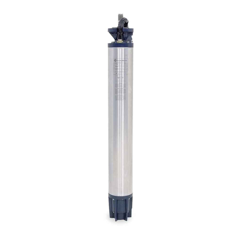
5 Connecting the motor cable
1. Remove plastic plug on the motor.
2. Clear plug and socket of dirt and moisture.
3. Apply a bit of silicone grease or vaseline to the rubber part of
the plug – pay attention that no grease reaches the electrical
contacts.
4. Insert plug into the socket until the socket thread becomes
YLVLEOHDJDLQ¿J
5. 1RZWXUQMDPQXWFRXQWHUFORFNZLVHXQWLO\RX¿QGWKHVWDUWRI
thread. Then turn clockwise and tighten it by hand, until com-
SUHVVLRQRIWKHUXEEHULVQRWLFHG1RZXVHDPPRSHQHQG
VSDQQHUWRWLJKWHQDQRWKHUWXUQ
Attention
The maximum tightening torque of the plug is 20
- 27 Nm. If the jam nut is tightened too much, the
plug will become leaky.
6. Route the motor leads along the pump and use the cable
guard to protect it from damage.
6 Extending the motor cable
The cable provided can be extended by the customer, by one of
the following means:
Apply non-permanent plug connection with Franklin Electric
7HUPLQDWLRQ.LWRUZLWKVWUDLQUHOLHI
8VHMRLQWVZLWKVKULQNKRVHVHDOLQJFRPSRXQGRU¿QLVKHGFD-
EOH¿WWLQJV3URWHFWMRLQWVDJDLQVWSHQHWUDWLQJPRLVWXUHVWULFWO\
IROORZPDQXIDFWXUHU¶VLQVWUXFWLRQV
Note
The plumbers themselves are responsible for the
correct selection and dimensioning of the drop
cable!
Extension cable must be approved for its use in the medium
and the prevailing temperatures.
7 Assembly of motor and unit
7KHVHLQVWUXFWLRQVUHIHUWRWKHPRWRURQO\3OHDVHstrictly observe
the assembly instructions of the pump manufacturer!
1. 3ODFHPRWRUDQGSXPSKRUL]RQWDOO\DQGOHYHO¿J
2. Turn motor shaft by hand before assembly. It must turn freely
after overcoming the adhesive friction.
3. Apply acid-free, waterproof grease to the coupling internal
toothing.
4. Remove hexagon nuts from the studs of the motor.
5. Align the pump so that its cable guard is in line with the lead
exit of the motor and guide pump and motor together.
6. If deemed necessary, place rings on the studs and tighten
the nuts crosswise. Strictly observe the tightening torques
of the unit manufacturer.
Attention
Check radial and axial clearance of the motor
shaft. There must be no rigid connection since
otherwise motor and pump will be damaged
during commissioning.
7. 3URWHFWFRXSOLQJVSRWDJDLQVWFRQWDFW
8 Electrical connection
3OHDVHREVHUYHWKHVSHFL¿FDWLRQVRQERWKWKHQDPHSODWHDQGWKH
enclosed data sheet. The following connection examples refer only
to the motor itself. They are no recommendation regarding the
control elements connected upstream.
1 Guidelines
The Franklin Electric submersible motors are a machine compo-
nent in accordance with the “machines“ EC guideline. You must not
commission the motor until you have:
manufactured a complete machine,
met the safety requirements stipulated in the applicable EC
JXLGHOLQHVDQGFRQ¿UPHGWKLVE\DFHUWL¿FDWHRIFRQIRUPLW\
2 Safety
The 4" submersible motor must only be operated in observance of
the following safety regulations:
2SHUDWHWKHPRWRURQO\XQGHUZDWHU¿J¿J
Take into account the implementation limits of motor and units
&KHFNWKHHOHFWULFDOV\VWHPDQGIXVLQJEHIRUHVZLWFKLQJRQ¿J
3URWHFWHOHFWULFDODQGPHFKDQLFDOGDQJHUVSRWVDJDLQVWDFFHVV
Vent rising pipe before commissioning in order to avoid water
hammers when starting-up
3URYLGHDFKHFNYDOYHLQWKHSXPSRUULVLQJSLSHPD[P
DZD\IURPSXPS¿J
:DWHUWHPSHUDWXUHZLWKRULJLQDOPRWRU¿OOLQJQRWEHORZ&
ZLWKZDWHU¿OOLQJQRWEHORZ&¿J
0D[LPXPZDWHUWHPSHUDWXUH&+LJKHUWHPSHUDWXUHVRQO\
ZLWKGHUDWHGPRWRUV¿J
:LWKJHQHUDWRURSHUDWLRQDOZD\VXQORDGWKHJHQHUDWRU¿UVWLH
Start: First the generator, then the motor
Switch-off: First the motor, then the generator
After powering the system check:
operating current of the motor at each phase
mains voltage with the motor running
level of the medium to be pumped
Switch off the motor immediately if:
Nameplate current is exceeded
YROWDJHWROHUDQFHVRIPRUHWKDQ+]+]
FRPSDUHGWRWKHUDWHGYROWDJHRQWKHPRWRUDUH
PHDVXUHG¿J
dry run is imminent
3 Intended use
)UDQNOLQ(OHFWULF6XEPHUVLEOH0RWRUVDUHVSHFL¿FDOO\designed for sub-
merged operation as drivers of variable torque loads such as pumps
i.e.
Drinking water supply
Wells in domestic houses, waterworks and agriculture
Dewatering, pressure boosting, irregation systems
Supply of process water
Ground water heating systems
Maximum 20 starts per hour, allow 60 seconds between
successive starts.
The maximum submergence depth is 150 meters. Up to
1000 meters after consulting Franklin Electric. Motors in 316
SS are available for operation in aggressive environments.
The responsibility for correct material choosing lies with the
customer.
Improper use of Franklin Electric Submersible Motors, like pumping of
air or explosive media is strictly prohibited.
Attention
For required motor cooling, please consult motor
QDPHSODWHHWFK,IFRROLQJÀRZLVQRWVXI¿FLHQW¿W
an inducer sleeve.
4 Transport and storage
Attention
The motor may be commissioned by trained and
instructed personnel only. Electrical connections
KDYHRQO\WREHFDUULHGRXWE\TXDOL¿HGSHUVRQQHO
Store motor in original packaging until assembly
Under no circumstances may the motor be stored at tempe-
UDWXUHVDERYH&VLQFHWKLVFDQOHDGWR¿OOLQJOLTXLGOHDNDJH
DQGSUHPDWXUHPRWRUIDLOXUH¿J
6WRUDJHWHPSHUDWXUHZLWKRULJLQDOPRWRU¿OOLQJXSWR&
ZLWKZDWHU¿OOLQJIURVWIUHH¿J


