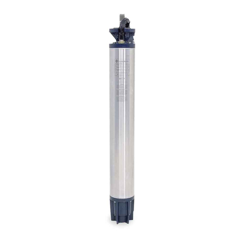
Franklin Electric SUBDRIVE CONNECT User manual

SSUUBBDDRRIIVVEE CCOONNNNEECCTT
Owner’s Manual

2
COPYRIGHT INFORMATION
Franklin Electric
Technical Publicati ns
9255 C verdale R ad
F rt Wayne, IN 46809
CC ppyyrriigghhtt ©© 22002222 FFrraannkklliinn EElleeccttrriicc,, CC ..,, IInncc.. AAllll RRiigghhttss RReesseerrvveedd
The entire c ntents f this publicati n are c pyrighted under United States law and pr tected by w rldwide c pyright laws and
treaty pr visi ns. N part f this material may be c pied, repr duced, distributed, republished, d wnl aded, displayed, p sted r
transmitted in any f rm by any means, including electr nic, mechanical, ph t c pying, rec rding, r therwise, with ut pri r written
permissi n f Franklin Electric. Y u may d wnl ad ne c py f the publicati n fr m www.franklinwater.c m nt a single c mputer
f r y ur pers nal, n n-c mmercial internal use nly. This is a single c py, single use license, n t a transfer f title, and is subject t
the f ll wing restricti ns: y u may n t m dify the materials, use them f r any c mmercial purp se, display them publicly, r re-
m ve any c pyright r ther pr prietary n tices fr m them.
The inf rmati n in this publicati n is pr vided f r reference nly and is subject t change with ut n tice. While every eff rt has
been made t ensure the accuracy f this manual at the time f release, ng ing pr duct impr vements and updates can render
c pies bs lete. Refer t www.franklinwater.c m f r the current versi n.
This publicati n is pr vided “as is” with ut warranties f any kind, either express r implied. T the fullest extent p ssible pursuant
t applicable law, Franklin Electric disclaims all warranties, express r implied, including but n t limited t , implied warranties f
merchantability, fitness f r a particular purp se, and n n-infringement f intellectual pr perty rights r ther vi lati n f rights.
Franklin Electric d es n t warrant r make any representati ns regarding the use, validity, accuracy, r reliability f the material in
this publicati n.
Under n circumstances, including but n t limited t , negligence, shall Franklin Electric be liable f r any direct, indirect, special, inci-
dental, c nsequential, r ther damages, including, but n t limited t , l ss f data, pr perty damage, r expense arising fr m, r in
any way c nnected with, installati n, perati n, use, r maintenance f the pr duct based n the material in this manual.
TTrraaddeemmaarrkkss uusseedd iinn tthhiiss ppuubblliiccaattiioonn::
The trademarks, service marks, and l g s used in this publicati n are registered and unregistered trademarks f Franklin Electric
and thers. Y u are n t granted, expressly, by implicati n, est ppel r therwise, any license r right t use any trademark, service
mark, r l g displayed n this site, with ut the express written permissi n f Franklin Electric.
FE L g and Design®, and Cerus™ are registered trademarks f Franklin Electric.
NEMA is a trademark f The Ass ciati n f Electrical Equipment and Medical Imaging Manufacturers.
NEC® is a registered trademark f the Nati nal Fire Pr tecti n Ass ciati n (NFPA).
UL® is a registered trademark f Underwriters Lab rat ries.
CSA is a registered mark f the CSA Gr up, f rmerly the Canadian Standards Ass ciati n
Bluet th is a registered trademark f Bluet th SIG, Inc.

3
TA LE OF CONTENTS
SAFETYINSTRUCTIONS ---------------------------------------- 5
HazardMessages ----------------------------------------- 5
Bef reGettingStarted -------------------------------------- 5
Pr ductSpecificPrecauti ns ----------------------------------- 6
PRODUCTINFORMATION --------------------------------------- 7
Descripti n--------------------------------------------- 7
Features ---------------------------------------------- 7
M dels ----------------------------------------------- 8
Applicati ns -------------------------------------------- 9
Three-Phase Pump Sizing and Perf rmance - - - - - - - - - - - - - - - - - - - - - - - - - - - 11
Generat rSizing------------------------------------------ 12
UNPACKINGANDINSPECTION ------------------------------------ 13
Transp rtati nandSt rage------------------------------------ 13
Unpacking --------------------------------------------- 13
What’sInTheB x----------------------------------------- 13
INSTALLATIONPLANNING --------------------------------------- 15
PlanningC nsiderati ns ------------------------------------- 15
Standard Submersible C nstant Pressure System - - - - - - - - - - - - - - - - - - - - - - - - 16
Typical Surface Pressure B sting Applicati n - - - - - - - - - - - - - - - - - - - - - - - - - 17
Minimum Pressure Tank and Supply Pipe Sizing - - - - - - - - - - - - - - - - - - - - - - - - 18
PHYSICALINSTALLATION --------------------------------------- 19
Envir nmentalRequirements----------------------------------- 19
M untingtheDrive ----------------------------------------20
DriveDimensi ns ----------------------------------------- 21
ELECTRICALINSTALLATION --------------------------------------23
WiringGuidelines -----------------------------------------23
ConduitLocationsandSizing -------------------------------- 25
P werWiringC nnecti ns ------------------------------------26
GroundConnections -------------------------------------26
C ntr lCircuitC nnecti ns------------------------------------28
DRIVECONFIGURATION ---------------------------------------- 31
Basic Setup (DIP SW1 — P siti n 1) - - - - - - - - - - - - - - - - - - - - - - - - - - - - - - - 31
M t r Phase Selecti n (DIP SW1 — P siti n 2) - - - - - - - - - - - - - - - - - - - - - - - - - 31
Applicati nTypeSelecti n ------------------------------------32
Submersible Motor and Pump Sizes (DIP SW2 DIP SW3) - - - - - - - - - - - - - - - - 32
Surface Motor Overload Size (DIP SW2 DIP SW3) - - - - - - - - - - - - - - - - - - - - 32
Pressure Input Selecti n (DIP SW1 — P siti n 5) - - - - - - - - - - - - - - - - - - - - - - - - 33
Perf rmanceSettings ---------------------------------------34
OPERATION-----------------------------------------------37
C ntr lFuncti ns ----------------------------------------- 37
MoistureSensor --------------------------------------- 37
M nit ringFuncti ns ---------------------------------------38
Pr tecti nFeatures ----------------------------------------38
OverTemperatureFoldback---------------------------------38
MotorSoftStart ---------------------------------------38
MotorOverloadProtection----------------------------------38
BrokenPipeProtection -----------------------------------39
UnderloadProtection ------------------------------------39
ADVANCEDAPPLICATIONOPTIONS --------------------------------- 41
Drive C ntr l Using an External Device (Auxiliary Input) - - - - - - - - - - - - - - - - - - - - 41
DuplexAlternat rFeature ------------------------------------ 41
SwitchingInterval --------------------------------------42
COMMUNICATIONS -------------------------------------------43

4
FEC nnectM bileApplicati n ----------------------------------43
MAINTENANCE ---------------------------------------------49
Tr ublesh ting ------------------------------------------49
Peri dicMaintenance ---------------------------------------55
SPECIFICATIONS --------------------------------------------57
SubDrive 15 C nnect/SubDrive 20 C nnect - - - - - - - - - - - - - - - - - - - - - - - - - - - 57
SubDrive 30 C nnect/SubDrive 50 C nnect - - - - - - - - - - - - - - - - - - - - - - - - - - - 58
Access ries --------------------------------------------59
ApplicableStandards ---------------------------------------60
STANDARDLIMITEDWARRANTY ----------------------------------- 61

5
SAFETY INSTRUCTIONS
Hazard Messages
This manual includes safety precauti ns and ther imp rtant in-
f rmati n in the f ll wing f rmats:
DANGER
Indicates an imminently hazardous situation
which, if not avoided, will result in death or
serious injury.
WARNING
Indicates a potentially hazardous situation
which, if not avoided, could result in death or
serious injury.
CAUTION
Indicates a potentially hazardous situation
which, if not avoided, could result in minor or
moderate personal injury.
NOTICE
Indicates a potentially hazardous situation
which, if not avoided could result in damage to
equipment or other property.
IMPORTANT: Identifies inf rmati n that c ntr ls c rrect assem-
blyand perati n f the pr duct.
NOTE: Identifies helpful r clarifying inf rmati n.
This symb l alerts the user t the presence f danger-
us v ltage inside the pr duct that might cause harm
r electrical sh ck.
This symb l alerts the user t the presence f h t sur-
faces that might cause fire r pers nal injury
efore Getting Started
This equipment sh uld be installed and serviced by technically
qualified pers nnel wh are familiar with the c rrect selecti n
and use f appr priate t ls, equipment, and pr cedures. Fail-
ure t c mply with nati nal and l cal electrical and plumbing
c des and within Franklin Electric rec mmendati ns may result
in electrical sh ck r fire hazard, unsatisfact ry perf rmance, r
equipment failure.
Read and f ll w instructi ns carefully t av id injury and pr p-
erty damage. D n t disassemble r repair unit unless de-
scribed in this manual.
Failure t f ll w installati n r perati n pr cedures and all ap-
plicable c des may result in the f ll wing hazards:
WARNING
High voltages capable of causing severe
injury or death by electrical shock are
present in this unit.
• T reduce risk f electrical sh ck, disc nnect p wer
bef re w rking n r ar und the system. M re than
ne disc nnect switch may be required t de-ener-
gize the equipment bef re servicing.
• Make sure the gr und terminal is c nnected t the
m t r, c ntr l encl sures, metal plumbing, and ther
metal near the m t r r cable using wire n smaller
than m t r cable wires.
CAUTION
Risk of bodily injury, electric shock,
or property damage.
• This equipment must n t be used by children r per-
s ns with reduced physical, sens ry r mental abil-
ities, r lacking in experience and expertise, unless
supervised r instructed. Children may n t use the
equipment, n r may they play with the unit r in the
immediate vicinity.
• Equipment can start aut matically. L ck ut-Tag ut
bef re servicing equipment.
• This equipment pr duces high temperatures during
n rmal perati n. Use cauti n when c ntacting
surfaces.
• Operati n f this equipment requires detailed instal-
lati n and perati n instructi ns pr vided in this
manual f r use with this pr duct. Read entire manual
bef re starting installati n and perati n. End User
sh uld receive and retain manual f r future use
• Keep safety labels clean and in g d c nditi n.
SAFETY INSTRUCTIONS
Hazard Messages

6
Product Specific Precautions
WARNING
High voltages capable of causing severe
injury or death by electrical shock are
present in this unit.
• D n t rem ve VFD c ver f r wiring r peri dic in-
specti ns while p wer is applied, r the unit is in
perati n.
• Capacit rs inside the drive can still h ld lethal v lt-
age even after p wer has been disc nnected—AL-
LOW 5 MINUTES FOR DANGEROUS INTERNAL
VOLTAGE TO DISCHARGE BEFORE REMOVING COV-
ER OR WORKING WITH INTERNAL COMPONENTS.
• Perf rm wiring after VFD has been m unted. Other-
wise, electric sh ck r b dily injury can ccur.
• D n t apply p wer t a damaged VFD r t VFD
with missing parts.
• D n t use VFD if p wer r m t r cable is damaged.
• D n t handle the VFD r c ntr l devices with wet
hands r when standing n a wet r damp surface,
r in water.
CAUTION
Risk of bodily injury, electric shock,
or property damage.
• Install VFD n a n n-flammable surface. D n t
place flammable materials nearby.
• Disc nnect the input p wer if VFD has been
damaged.
• D n t t uch VFD after shutting d wn r disc nnect-
ing it. It can remain h t f r a few minutes.
• D n t all w lint, paper, w d chips, dust, metallic
chips r ther f reign material int the drive.
• S me VFD parameters are set as default t aut -
matically start VFD in s me applicati ns. Disable
these parameters if aut matic start is n t safe f r
pers nnel r equipment.
• If required, pr vide an emergency mechanical brake
t prevent any hazard us c nditi ns if VFD fails dur-
ing perati n.
NOTICE
Risk of damage to drive or other equipment.
• Install and wire VFD acc rding t the instructi ns in
this manual.
• Take pr tective measures against ESD (Electr static
Discharge) bef re t uching c ntr l b ards during in-
specti n, installati n r repair.
• D n t c nnect p wer fact r c rrecti n capacit rs,
surge suppress rs, r RFI filter t the VFD utput.
• Check if input p wer v ltage is within acceptable
range bef re applying p wer t VFD.
• Set c rrect m t r data fr m the m t r nameplate
and verl ad pr tecti n parameters f r pr per m -
t r verl ad pr tecti n.
• D n t m dify VFD internal c mp nents and circuits.
• The use f any disc nnecting device (c ntact r, dis-
c nnect etc.) in m t r circuit during VFD run can
cause damage t VFD p wer c mp nents. St p VFD
bef re pening the m t r circuit with disc nnect r
c ntact r.
• This pr duct is rec mmended f r use with Franklin
Electric 4-inch submersible m t rs as specified in
this manual. Use f this unit with any ther Franklin
Electric m t r r with m t rs fr m ther manufac-
turers may result in damage t b th m t r and
electr nics.
• In applicati ns where water delivery is critical, a re-
placement pressure sens r and/ r back-up system
sh uld be readily available if the drive fails t per-
ate as intended.
SAFETY INSTRUCTIONS
Product Specific Precautions

7
PRODUCT INFORMATION
Description
The Franklin Electric SubDrive C nnect pr duct family includes variable frequency drives (VFD) designed t c ntr l and pr tect
3-wire, single- r three-phase m t rs, enhancing pump perf rmance f r residential and light c mmercial water system applica-
ti ns. When used with Franklin Electric m t rs, the SubDrive C nnect drives a m t r and pump at variable speeds t maintain
c nstant water pressure, even as user demands (water fl w) change.
The SubDrive C nnect series pr vides the capability t use a three-phase m t r with single-phase inc ming p wer, which adds
new efficiency and quiet perf rmance t rural h mes and businesses.
Features
CCoonnffiigguurraattiioonn
• C mpatible with submersible and surface pumps and m t rs, including Franklin
Electric MagF rce permanent magnet submersible m t rs.
• Three-phase perati n all ws enhanced water delivery perf rmance using a
smaller pump with a standard rated m t r
• N pr gramming required with easy DIP switch setup
• Built-in Duplex Alternat r f r Lead/Lag pump perati n
• W rks with small pressure tanks r existing larger tanks
OOppeerraattiioonn
• Easy-t -read LCD display f r system status identificati n
• User-defined m t r frequency range and c ntr l inputs.
• Auxiliary c ntr l input all ws f r additi nal external c ntr l
• Run and alarm relays pr vide switching f r external m nit rs r systems
• Active P wer Fact r C rrecti n (PFC) reduces average current used by the
drive
• Advanced filtering t rem ve radi frequency interference
PPrrootteeccttiioonn
• Pr tecti n against sh rt circuit, under-l ad, verheat, under-v ltage, surges, pen circuit
• Br ken-pipe detecti n
• User-defined underl ad sensitivity and ff time
• Gr und Fault Pr tecti n f r m t r utput
• M isture Sens r input st ps pump when water is detected.
• S ft-start feature prevents water hammer and increases m t r life
CCoommmmuunniiccaattiioonn
• The FE C nnect m bile app can be used t adjust advanced settings, m nit r drive characteristics, and view fault hist ry.
PRODUCT INFORMATION
Description

9
Applications
Three-Phase Submersible Applications
Motor and Pump Combination SubDrive 50 SubDrive 30 SubDrive 20 SubDrive 15
1.0 hp (0.75 kW) 234513-series m t r with:
• 0.5 hp (0.37 kW),
• 0.75 hp (0.55 kW), r
• 1.0 hp (0.75 kW) pump
√ √ √ √
1.5 hp (1.1 kW) 234514-series m t r with:
• 0.75 hp (0.55 kW),
• 1.0 hp (0.75 kW), r
• 1.5 hp (1.1 kW) pump
√ √ √ √
2.0 hp (1.5 kW) 234315-series m t r with:
• 1.0 hp (0.75 kW),
• 1.5 hp (1.1 kW), r
• 2.0 hp (1.5 kW) pump
√ √ √
3.0 hp (2.2 kW) 234316-series m t r with:
• 1.5 hp (1.1 kW),
• 2.0 hp (1.5 kW), r
• 3.0 hp (2.2 kW) pump
√ √
5.0 hp (3.7 kW) 234317-series m t r with:
• 3.0 hp (2.2 kW), r
• 5.0 hp (3.7 kW) pump
√
Refer t “Three-Phase Pump Sizing and Perf rmance” n page 11 when selecting a pump.
M t r and pump HP are pr grammed thr ugh DIP switch settings. Refer t “Submersible M t r and
Pump Sizes (DIP SW2 & DIP SW3)” n page 32.
PRODUCT INFORMATION
Applications

10
Three-Phase MagForce Permanent Magnet Motor Applications
Motor and Pump Combination SubDrive 50 SubDrive 30 SubDrive 20
1.5hp (1.1kW) 234055-series MagF rce permanent magnet m -
t r with:
• 0.75hp (0.55kW)
• 1.0hp (0.75kW), r
• 1.5hp (1.1kW) pump
√ √ √
2.0hp (1.5kW) 234052-series MagF rce permanent magnet
m t r with:
• 1.0hp (0.75kW)
• 1.5hp (1.1kW), r
• 2.0hp (1.5kW) pump
√ √ √
3.0hp (2.2kW) 234052-series MagF rce permanent magnet
m t r with:
• 1.5hp (1.1kW)
• 2.0hp (1.5kW), r
• 3.0hp (2.2kW) pump
√ √
5.0hp (3.7kW) 234054-series MagF rce permanent magnet
m t r with:
• 3.0hp (2.2kW) r
• 5.0hp (3.7kW) pump
√
Single-Phase (3–Wire) Submersible Applications
Motor and Pump Combination SubDrive 50 SubDrive 30 SubDrive 20 SubDrive 15
0.5 hp (0.37 kW) 214505-series m t r with:
• 0.5 hp (0.37 kW) pump √ √ √ √
0.75 hp (0.55 kW) 214507-series m t r with:
• 0.75 hp (0.55 kW) pump √ √ √ √
1.0 hp (0.75 kW) 214508-series m t r with:
• 1.0 hp (0.75 kW) pump √ √ √ √
1.5 hp (1.1 kW) 224300-series m t r with:
• 1.5 hp (1.1 kW) pump √ √ √
2.0 hp (1.5 kW) 224301-series m t r with:
• 2.0 hp (1.5 kW) pump √ √ √
3.0 hp (2.2 kW) 224302-series m t r with:
• 3.0 hp (2.2 kW) pump √
PRODUCT INFORMATION
Applications

11
SubDrive Connect Models with Surface Motor Capacity Ratings
SubDrive C nnect m dels will perate many Franklin Electric surface m unted pumps, including VR, MH,
BT4, and DDS series.
NOTE: Rec mmended f r use n inverter duty rated m t rs. F ll w m t r manufacturer rec mmenda-
ti ns f r cable lengths when using variable frequency drives.
When perating a surface system, drives are c nfigured based n m t r current capacity rather than
h rsep wer. M t r current capacity is pr grammed thr ugh DIP switch settings. Refer t “System Re-
sp nse (DIP SW3)” n page 34.
Model Current Capacity
SubDrive15 2.0 – 5.9 A, 230 VAC three-phase
SubDrive20 2.0 – 8.1 A, 230 VAC three-phase
SubDrive30 2.0 – 10.9 A, 230 VAC three-phase
SubDrive50 2.0– 17.8 A, 230 VAC three-phase
NOTE: Using the FE C nnect M bile App, m t r verl ad current can be set fr m 2.0 A up t the max
current rating f the drive m del in 0.1 A increments. Refer t “Drive C nfigurati n Using the FE C nnect
App” n page 44.
Three-Phase Pump Sizing and Performance
SubDrive C nnect m dels are capable f driving a smaller threep-
hase pump, either standard inducti n r MagF rce permanent
magnet, than the m t r h rsep wer rating t a similar r better
perf rmance than a c nventi nally matched pump and m t r. This
has the effect f extending the perf rmance curve f the verall
system at b th l w and high fl w rates. See the example at right.
T select the pr per pump f r y ur applicati n, first ch se the
c nventi nally matched pump and m t r c mbinati n that meets
the head and fl w requirements. Refer t the Franklin Electric AIM
Manual.
Then, select an appr priate smaller pump fr m the same pump
series (fl w rating) that w rks with y ur SubDrive C nnect m del.
Refer t “Applicati ns” n page 9.
The m t r and pump sizes must be c nfigured using DIP switch
settings n the SubDrive C nnect. Refer t “Submersible M t r
and Pump Sizes (DIP SW2 & DIP SW3)” n page 32.
PRODUCT INFORMATION
Three-Phase Pump Sizing and Performance

12
Generator Sizing
Basic generat r sizing f r the SubDrive C nnect system is 1.5 times the maximum input watts c nsumed
by the drive, r unded up t the next n rmal-sized generat r.
Rec mmended minimum generat r sizes:
Model Generator Watts
SubDrive 15 3500
SubDrive 20 5700
SubDrive 30 7000
SubDrive 50 11000
IMPORTANT: D n t use with a Gr und Fault Circuit Interrupter (GFCI). If using an externally regulated
generat r, verify that the v ltage, hertz, and idle speed are appr priate t supply the drive.
PRODUCT INFORMATION
Generator Sizing

13
UNPACKING AND INSPECTION
Transportation and Storage
NOTICE
Risk of damage to VFD or other equipment.
• D n t stack drive b xes higher than standard 48” cube height when palleting f r st rage.
• D n t place heavy items n VFD.
• D n t dr p VFD r subject it t hard impact.
• Disp se f VFD pr perly as industrial equipment waste.
The VFD sh uld be st red in the shipping cart n r crate bef re installati n.
Unpacking
CAUTION
Risk of personal injury or damage to VFD or other equipment.
• Use suitable lifting equipment, in g d c nditi n, rated f r at least 5 times the weight f
the drive.
1. Inspect exteri r f package f r shipping damage. If there is damage, n tify the shipping agent and
y ur sales representative.
2. Make sure the part number and pr duct ratings n the identificati n label are c rrect f r the
applicati n.
3. Rem ve drive fr m the b x and check f r damage.
4. Rem ve the drive c ver and make sure the pr duct ratings n the nameplate match the package
label.
What’s In The ox
1. Variable Frequency Drive (VFD)
2. Pressure Transducer
3. Transducer Cable
4. Screwdriver/Adjustment T l
5. Strain Relief Fitting
6. Owner’s Manual
UNPACKING AND INSPECTION
Transportation and Storage

14

15
INSTALLATION PLANNING
Planning Considerations
1 2 3 4 5 6
Plan System Goals Identify Options Select Control
Methods
Install VFD
Hardware Install Wiring Program
Parameters
Intended Functi n
• C nstant Pres-
sure Water
Systems
• Pressure
B sting
Hardware
Applicati n
• Centrifugal
Pump
• Submersible
Pump
• Single- r
Three-Phase
M t r Type
• FE MagF rce
• Inducti n
Aut mati n
• System
Resp nse
• Bump M de
• Drawd wn
• Steady Fl w
Desired Pr tecti n
• Br ken Pipe
• Underl ad
• M t r Gr und
Fault
• M isture
Sens r
Multi Pump
• Duplex
Alternat r
• Lead/Lag
Run/Speed/St p
• Hand/Aut
• Transducer/
Sens r
• P tenti meter
• Switches/
Fl ats
C mmunicati ns
• FE C nnect
M bile App
• Drive-t -drive
• Aux C ntr l
Input
• Relay Out
L cati n
• Inside
• Outside
Drive Size
• Clearance
• Drilling
Distance t the
Well
• Wire sizes
• Filtering
requirements
Climate C ntr l
• Temperature
• M isture
C nduit Rules
• R uting
• Separati n
P wer C nnecti ns
• Gr unding
• Inputs
• Outputs
C ntr l circuits
• Feedback
inputs
• Relay Outputs
• C mmunica-
ti ns
Basic Pr gramming
• Applicati n
• M t r ratings
• Setp ints
I/O setup
• Input functi ns
• Output
functi ns
Other Available
Opti ns
• Enable features
1. The planned usage f the verall system will determine which pti ns and c ntr l meth ds are ap-
pr priate, as well as h w the VFD sh uld be installed and pr grammed. Refer t the f ll wing pages
f r examples f h w the system might be used.
2. System pti ns define and aut mate features that supp rt the intended perati n. These features
may require specialized c ntr l meth ds and pr gramming. F r m re details, refer t “Drive C nfig-
urati n” n page 31,“Operati n” n page 37, and “Advanced Applicati n Opti ns” n page 41.
3. The SubDrive C nnect supp rts several meth ds f r aut mating pump m t r speed c ntr l. Refer t
“Drive C nfigurati n” n page 31 f r p ssible c ntr l setups.
4. The verall functi n f the system directly affects where and h w the VFD sh uld be m unted. Refer
t “Physical Installati n” n page 19 f r guidelines.
5. The selected m t r applicati n, al ng with the c ntr l meth d(s), determines h w the VFD sh uld
be c nnected. Refer t “Electrical Installati n” n page 23 f r m re inf rmati n.
6. The VFD can be quickly and easily pr grammed f r m st standard perati ns. Refer t “Drive C n-
figurati n” n page 31. Advanced features r pti ns may require additi nal adjustments t achieve
the desired perf rmance. Refer t “Advanced Applicati n Opti ns” n page 41 and “Drive C nfigura-
ti n Using the FE C nnect App” n page 44.
INSTALLATION PLANNING
Planning Considerations

16
Standard Submersible Constant Pressure System
The ab ve drawing illustrates h w a typical submersible pump system sh uld be arranged f r a c nstant
pressure applicati n.
1. PPuummpp aanndd MM tt rr AAsssseemmbbllyy:: Refer t the Franklin Electric AIM Manual f r pump, pipe, and cable
sizing inf rmati n.
2. CChheecckk VVaallvvee
3. PPrreessssuurree RReelliieeff VVaallvvee::
CAUTION
Risk of bodily injury or property damage.
• Pumps can devel p very high pressure in s me situati ns. Always install a pressure re-
lief valve able t pass full pump fl w up t 100 psi.
• Install the pressure relief valve near the pressure tank and r ute t a drain capable f
full system fl w.
4. PPrreessssuurree TTaannkk:: Refer t “Minimum Pressure Tank and Supply Pipe Sizing” n page 18.
5. PPrreessssuurree GGaauuggee
6. PPrreessssuurree TTrraannssdduucceerr rr SSeennss rr:: Install in a vertical p siti n after the pressure tank, and within 6 ft
(1.8 m) f the tank t minimize pressure fluctuati ns. There sh uld be n elb ws between the tank
and sens r.
7. VVFFDD
8. PP wweerr SSuuppppllyy ffrr mm CCiirrccuuiitt BBrreeaakkeerr:: Single phase
9. PP wweerr tt MM tt rr:: Three-Phase
INSTALLATION PLANNING
Standard Submersible Constant Pressure System

17
Typical Surface Pressure oosting Application
The ab ve drawing illustrates h w a typical surface m unted pump system sh uld be arranged f r a
pressure b sting applicati n.
1. WWaatteerr SSuuppppllyy
2. CChheecckk VVaallvvee
3. BBaallll VVaallvvee
4. PPrreessssuurree RReelliieeff VVaallvvee::
CAUTION
Risk of bodily injury or property damage.
• Pumps can devel p very high pressure in s me situati ns. Always install a pressure re-
lief valve able t pass full pump fl w up t 100 psi.
• Install the pressure relief valve near the pressure tank and r ute t a drain capable f
full system fl w.
5. PPrreessssuurree TTaannkk:: Refer t “Minimum Pressure Tank and Supply Pipe Sizing” n page 18.
6. PPrreessssuurree GGaauuggee
7. PPrreessssuurree TTrraannssdduucceerr rr SSeennss rr:: Install in a vertical p siti n after the pressure tank, and within 6 ft
(1.8 m) f the tank t minimize pressure fluctuati ns. There sh uld be n elb ws between the tank
and sens r.
8. VVFFDD
9. PP wweerr SSuuppppllyy ffrr mm EElleeccttrriiccaall PPaanneell:: Single phase (sh wn) 208/230 VAC ± 10%
10. PP wweerr tt MM tt rr:: Three-Phase.
11. OOppttii nnaall BByyppaassss:: F r system maintenance.
IMPORTANT: If the pump is equipped with a built-in pressure switch, the p wer wires fr m the VFD
must bypass the pressure switch and c nnect directly t the m t r.
INSTALLATION PLANNING
Typical Surface Pressure oosting Application

18
Minimum Pressure Tank and Supply Pipe Sizing
A VFD system needs nly a small pressure tank t maintain c nstant pressure, alth ugh a larger tank
may be used.
• If adding a drive t a system with an existing large tank, refer t “Tank Size and Bump M de Adjust-
ments (FE C nnect App Only)” n page 35.
• The pressure tank pre-charge setting sh uld be 70% f the targeted system pressure.
Refer t the f ll wing rec mmendati ns f r best perf rmance.
Submersible Pump Applications
Pump Flow Rating VFD Model Minimum Tank Size
Less than 12 gpm (45.4 lpm)
SubDrive 15 2 gall ns (7.6 liters)
SubDrive 20 4 gall ns (15.1 liters)
SubDrive 30 4 gall ns (15.1 liters)
SubDrive 50 8 gall ns (30.3 liters)
12 gpm (45.4 lpm) and higher
SubDrive 15 4 gall ns (15.1 liters)
SubDrive 20 8 gall ns (30.3 liters)
SubDrive 30 8 gall ns (30.3 liters)
SubDrive 50 20 gall ns (75.7 liters)
Surface Pump Applications
Maximum Pump Flow Minimum Tank Size
10 GPM 2 gall ns (7.6 liters)
20 GPM 4 gall ns (15.1 liters)
30 GPM 4 gall ns (15.1 liters)
40 GPM 8 gall ns (30.3 liters)
Minimum Supply Pipes
The minimum supply pipe diameter past the pressure sens r (transducer) sh uld be selected n t t ex-
ceed a maximum vel city f 8 feet per sec nd (2.4 m/s) based n the fl w rate f the system.
IMPORTANT: Water system piping sh uld be perf rmed by an experienced pr fessi nal t ensure ad-
equate fl w.
Maximum GPM (lpm) Minimum Pipe Diameter
11.0 (41.6) 0.75 in.
19.6 (74.2) 1 in.
30.6 (115.8) 1.25 in.
44.1 (166.9) 1.5 in.
78.3 (296.4) 2 in.
122.4 (463) 2.5 in.
176.3 (667) 3 in.
240.0 (908) 3.5 in.
313.3 (1186) 4 in.
396.6 (1501) 4.5 in.
489.6 (1853) 5 in.
INSTALLATION PLANNING
Minimum Pressure Tank and Supply Pipe Sizing

19
PHYSICAL INSTALLATION
Environmental Requirements
NOTICE
Risk of damage to VFD, or malfunction can occur due to improper handling, in-
stallation, or environment.
• D n t m unt VFD n equipment with excessive vibrati n.
• Install in a l cati n where temperature is within the range f pr duct rating.
• M unt VFD vertically (t p up) f r pr per heat dissipati n.
• D n t m unt VFD in direct sunlight r near ther heat s urces.
• D n t install in c rr sive envir nments.
• Install at least 18” (45.7 cm) ab ve the gr und.
• Installati n f n n-appr ved screening may damage the drive and/ r reduce utput.
The drive is intended f r perati n in ambient temperatures fr m -13 °F t 122 °F
(-25 °C t 50°C).
The drive electr nics are air-c led. All w at least 6 inches (15.24 cm) f clearance
ar und the unit f r air fl w.
SSppeecciiaall CCoonnssiiddeerraattiioonnss ffoorr OOuuttddoooorr UUssee
The drive is suitable f r utd r use with a NEMA 3R rating; h wever, the f ll wing
c nsiderati ns sh uld be made f r utd r installati ns:
• M unt the drive n a wall r back plate that is at least 6 inches (15.24 cm) larg-
er than the uter dimensi ns f the encl sure t maintain the NEMA 3R rating.
• M unt the unit vertically with the wiring end riented d wnward, and pr perly
secure the c ver (als applies t ind r installati ns).
• Pr tect fr m h se-directed r sprayed water as well as bl wing rain. NEMA 3R
encl sures are capable f withstanding d wnward-directed rain nly. Failure t d s may result in drive failure.
• Install away fr m direct sunlight r l cati ns subject t extreme temperatures r humidity.
• Use appr priate screening f r the air inlet and utlet when installed in areas where insect r small animal intrusi n is an is-
sue. Refer t “Access ries” n page 59 f r rdering inf rmati n.
• Clean screens n a regular basis t ensure pr per airfl w.
PHYSICAL INSTALLATION
Environmental Requirements

20
Mounting the Drive
CAUTION
Risk of bodily injury or damage to drive or other equipment.
• The drive must be m unted n a structure such as a wall r p st capable f supp rting
the weight f the unit.
• Install VFD n a n n-c mbustible surface.
• Ensure suitable m unting hardware is used when installing the drive.
• D n t install the drive n unreinf rced drywall.
• Use tw pers ns when lifting the drive f r transp rt r installati n. If using lifting equip-
ment, it must be in g d c nditi n and rated f r at least 5 times the weight f the drive.
• Wear pr tective gl ves while installing the drive t guard against sharp edges.
The m unting l cati n sh uld have nearby access t an appr priate electrical supply and access t the
m t r wiring. Refer t “Electrical Installati n” n page 23.
Use lag screws r b lts appr priate f r supp rting the weight f the drive.
IMPORTANT: D n t drill h les in the drive.
1. M unt the drive using the hanging tab n the t p side f the encl sure.
IMPORTANT: T p screw sh uld attach t a s lid structure such as a stud r brace.
2. Secure the tw additi nal m unting h les n the back side.
IMPORTANT: All three screw h le l cati ns sh uld be used t ensure the drive is securely m unted.
PHYSICAL INSTALLATION
Mounting the Drive
This manual suits for next models
8
Table of contents
Languages:
Other Franklin Electric Engine manuals

Franklin Electric
Franklin Electric 214 Series Parts list manual

Franklin Electric
Franklin Electric 226 Series Installation instructions

Franklin Electric
Franklin Electric 214 Series Installation instructions

Franklin Electric
Franklin Electric 264 Series User manual

Franklin Electric
Franklin Electric HMX-1 User manual

Franklin Electric
Franklin Electric 214 Series User manual